EP1213482A1 - Vakuumpumpe - Google Patents
Vakuumpumpe Download PDFInfo
- Publication number
- EP1213482A1 EP1213482A1 EP01310055A EP01310055A EP1213482A1 EP 1213482 A1 EP1213482 A1 EP 1213482A1 EP 01310055 A EP01310055 A EP 01310055A EP 01310055 A EP01310055 A EP 01310055A EP 1213482 A1 EP1213482 A1 EP 1213482A1
- Authority
- EP
- European Patent Office
- Prior art keywords
- mechanism portion
- pump
- pump mechanism
- vacuum
- spiral
- Prior art date
- Legal status (The legal status is an assumption and is not a legal conclusion. Google has not performed a legal analysis and makes no representation as to the accuracy of the status listed.)
- Withdrawn
Links
- 230000007246 mechanism Effects 0.000 claims abstract description 154
- 238000000034 method Methods 0.000 claims abstract description 50
- 238000010276 construction Methods 0.000 claims description 24
- 230000004888 barrier function Effects 0.000 claims description 2
- 230000008569 process Effects 0.000 abstract description 41
- 230000009467 reduction Effects 0.000 abstract description 6
- 230000004043 responsiveness Effects 0.000 abstract description 6
- 230000003247 decreasing effect Effects 0.000 abstract description 2
- 239000007789 gas Substances 0.000 description 57
- IJGRMHOSHXDMSA-UHFFFAOYSA-N Atomic nitrogen Chemical compound N#N IJGRMHOSHXDMSA-UHFFFAOYSA-N 0.000 description 8
- 229910001873 dinitrogen Inorganic materials 0.000 description 8
- 125000006850 spacer group Chemical group 0.000 description 6
- 230000007423 decrease Effects 0.000 description 5
- 238000004519 manufacturing process Methods 0.000 description 4
- 239000004065 semiconductor Substances 0.000 description 4
- 230000003993 interaction Effects 0.000 description 3
- 238000007796 conventional method Methods 0.000 description 2
- 230000008901 benefit Effects 0.000 description 1
- 230000008859 change Effects 0.000 description 1
- 238000001312 dry etching Methods 0.000 description 1
- 238000002474 experimental method Methods 0.000 description 1
- 230000004927 fusion Effects 0.000 description 1
- 238000012986 modification Methods 0.000 description 1
- 230000004048 modification Effects 0.000 description 1
- 239000002245 particle Substances 0.000 description 1
Images
Classifications
-
- F—MECHANICAL ENGINEERING; LIGHTING; HEATING; WEAPONS; BLASTING
- F04—POSITIVE - DISPLACEMENT MACHINES FOR LIQUIDS; PUMPS FOR LIQUIDS OR ELASTIC FLUIDS
- F04D—NON-POSITIVE-DISPLACEMENT PUMPS
- F04D19/00—Axial-flow pumps
- F04D19/02—Multi-stage pumps
- F04D19/04—Multi-stage pumps specially adapted to the production of a high vacuum, e.g. molecular pumps
- F04D19/046—Combinations of two or more different types of pumps
-
- F—MECHANICAL ENGINEERING; LIGHTING; HEATING; WEAPONS; BLASTING
- F04—POSITIVE - DISPLACEMENT MACHINES FOR LIQUIDS; PUMPS FOR LIQUIDS OR ELASTIC FLUIDS
- F04D—NON-POSITIVE-DISPLACEMENT PUMPS
- F04D19/00—Axial-flow pumps
- F04D19/02—Multi-stage pumps
- F04D19/04—Multi-stage pumps specially adapted to the production of a high vacuum, e.g. molecular pumps
-
- F—MECHANICAL ENGINEERING; LIGHTING; HEATING; WEAPONS; BLASTING
- F04—POSITIVE - DISPLACEMENT MACHINES FOR LIQUIDS; PUMPS FOR LIQUIDS OR ELASTIC FLUIDS
- F04D—NON-POSITIVE-DISPLACEMENT PUMPS
- F04D17/00—Radial-flow pumps, e.g. centrifugal pumps; Helico-centrifugal pumps
- F04D17/08—Centrifugal pumps
- F04D17/16—Centrifugal pumps for displacing without appreciable compression
- F04D17/168—Pumps specially adapted to produce a vacuum
-
- F—MECHANICAL ENGINEERING; LIGHTING; HEATING; WEAPONS; BLASTING
- F04—POSITIVE - DISPLACEMENT MACHINES FOR LIQUIDS; PUMPS FOR LIQUIDS OR ELASTIC FLUIDS
- F04D—NON-POSITIVE-DISPLACEMENT PUMPS
- F04D25/00—Pumping installations or systems
- F04D25/16—Combinations of two or more pumps ; Producing two or more separate gas flows
-
- F—MECHANICAL ENGINEERING; LIGHTING; HEATING; WEAPONS; BLASTING
- F04—POSITIVE - DISPLACEMENT MACHINES FOR LIQUIDS; PUMPS FOR LIQUIDS OR ELASTIC FLUIDS
- F04D—NON-POSITIVE-DISPLACEMENT PUMPS
- F04D27/00—Control, e.g. regulation, of pumps, pumping installations or pumping systems specially adapted for elastic fluids
- F04D27/02—Surge control
- F04D27/0261—Surge control by varying driving speed
-
- Y—GENERAL TAGGING OF NEW TECHNOLOGICAL DEVELOPMENTS; GENERAL TAGGING OF CROSS-SECTIONAL TECHNOLOGIES SPANNING OVER SEVERAL SECTIONS OF THE IPC; TECHNICAL SUBJECTS COVERED BY FORMER USPC CROSS-REFERENCE ART COLLECTIONS [XRACs] AND DIGESTS
- Y02—TECHNOLOGIES OR APPLICATIONS FOR MITIGATION OR ADAPTATION AGAINST CLIMATE CHANGE
- Y02B—CLIMATE CHANGE MITIGATION TECHNOLOGIES RELATED TO BUILDINGS, e.g. HOUSING, HOUSE APPLIANCES OR RELATED END-USER APPLICATIONS
- Y02B30/00—Energy efficient heating, ventilation or air conditioning [HVAC]
- Y02B30/70—Efficient control or regulation technologies, e.g. for control of refrigerant flow, motor or heating
Definitions
- the present invention relates to a vacuum pump used for a semiconductor manufacturing apparatus, an electron microscope, a surface analyzing apparatus, a mass spectroscope, a particle accelerator, a nuclear fusion experiment apparatus, etc.
- Semiconductor manufacturing involves processes such as dry etching, CVD and the like. These processes are implemented in a vacuum vessel called a process chamber.
- a process chamber As methods for controlling process pressure in this process chamber, (1) a method of using a conductance valve and (2) a system of introducing gas to a chamber by utilizing amass flow control (hereinafter, abbreviated as "MFC") are known. Further, (3) a system of introducing gas to an exhaust side of a turbo molecular pump for evacuating the process chamber is also proposed.
- MFC amass flow control
- the conductance valve is installed to a gas inlet of the vacuum pump connected with the process chamber.
- a flow rate (called conductance) of gas flowing from this process chamber to the side of the vacuum pump is adjusted, thereby controlling the process pressure in the process chamber.
- the conductance valve of the above-described (1) is expensive and large. Further, since the conductance valve includes an operating portion for opening and closing the valve, its responsiveness is limited. In the conventional system applying this kind of conductance valve to control the process pressure, there are problems such as high cost and increased size of the overall apparatus. Further, the conventional system has a problem in that it is impossible to control the process pressure with high responsiveness.
- the above-described method of (2) using MFC has problems in that the composition of process gas is changed, and that the follow-up property is low.
- the system introducing nitrogen gas of the above-described (3) requires a gas piping for supplying nitrogen gas to the side of the vacuum pump and a flow rate controlling apparatus and the like for adjusting the supply amount of nitrogen gas. Therefore, the overall construction of the apparatus is rather complex and the overall size of the apparatus becomes large. Further, every time the process pressure is controlled, nitrogen gas is consumed. Therefore, it also has a problem of high running cost.
- An object of the present invention is to provide a vacuum pump capable of controlling the process pressure with high responsiveness and which allows miniaturization and reduction of cost of the overall apparatus, as well as reduction of the running cost.
- a vacuum pump characterized by comprising a gas inlet connected with a vacuum vessel side, a first pump mechanism portion for inhaling gas in the vacuum vessel from the gas inlet and for exhausting the gas, a gas outlet communicated with an exhaust side of the first pump mechanism portion, and a second pump mechanism portion capable of changing the pump speed of rotation independently of the first pump mechanism portion is provided on the way of an exhaust passage communicating the exhaust side of the first pump mechanism portion with the gas outlet,
- the present invention is characterized in that the pressure in the vacuum vessel is controlled by changing the pump speed of rotation of the second pump mechanism portion.
- the present invention is characterized in that the second pump mechanism portion having a spiral pump mechanism portion.
- the present invention is characterized in that the first pump mechanism portion has a compound-type pump construction in which a turbo molecular pump mechanism portion disposed on a high-vacuum side with a thread groove pump mechanism portion disposed at a lower section of this turbo molecular pump mechanism portion are formed integrally.
- the present invention when the pump speed of rotation of the second pump mechanism portion is changed, the backing pressure (the pressure of the exhaust side) of the first pump mechanism portion changes. For example, when the backing pressure is increased, the efficiency of gas suction from the gas inlet to the first pump mechanism portion side is reduced, and then the pressure in the process chamber is increased. Therefore, the present invention is capable of controlling the process pressure in the process chamber by changing the pump speed of rotation of the second pump mechanism portion.
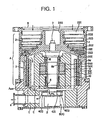
- the vacuum pump of the present invention shown in Fig. 1 is configured such that a first pump mechanism portion A and a second pump mechanism portion B are contained in a cylindrical pump case 1.
- the upper side of the pump case 1 is equipped with a gas inlet 5.
- a lower side of the pump case 1 is equipped with a gas outlet 6.
- the first pump mechanism portion A is installed on the gas inlet 5 side of this pump case 1.
- the second pump mechanism portion B is installed on the way of an exhaust passage C communicating an exhaust side Aout of this first pump mechanism portion A with the gas exhaust port 6 equipped at the lower portion of the pump case 1.
- the gas inlet 5 is connected with a vacuum vessel side in a high vacuum, such as a process chamber of a semiconductor manufacturing apparatus or the like.
- the gas outlet 6 is communicated with the atmosphere side.
- the pump construction in the present embodiment employs a compound-type pump construction integrating a turbo molecular pump mechanism portion 2 having an exhaust function of a turbo molecular pump system with a thread groove pump mechanism portion 3 having an exhaust function of a thread groove pump system.
- the turbo molecular pump mechanism portion 2 is disposed at the high-vacuum side, that is, at the gas inlet 5 side of the upper portion of the pump case 1.
- the thread groove pump mechanism B is disposed at the side of the lower section of the turbo molecular pump mechanism portion 2.
- the turbo molecular pump mechanism portion 2 is provided with a plurality of processed rotor blades 201 and stator blades 202 in the outer periphery of a rotatably installed cylindrical rotor 200.
- the upper end of the rotor 200 is directed to the gas inlet 5 side.
- the rotor blades 201 and the stator blades 202 are alternately arranged along a rotation center axis of the rotor 200.
- the rotor blades 201 are processed integrally with the rotor 200 and are capable of rotating integrally with the rotor 200.
- the stator blades 202 are fixed to the inner surface of the pump case 1 through spacers 203.
- the turbo molecular pump mechanism portion 2 having the above-described construction exhausts gas molecule by utilizing interaction between the rotatable rotor blades 201 and the fixed stator blades 202. This exhaust operation is capable of producing high vacuum (degree of vacuum: 10 -6 Pa).
- the thread groove pump mechanism portion 3 is composed of a rotatably installed cylindrical rotor 300 and thread groove spacers 301.
- the rotor 300 of this thread groove pump mechanism portion 3 is provided integrally with the lower portion of the rotor 200 as a skirt of the rotor 200 of the turbo molecular pump mechanism portion 2. Further, the rotor 300 is formed on the same axis of the rotor 200 of the turbo molecular pump mechanism portion 2.
- One of thread groove spacers 301 is arranged on the inside of the rotor 300 and the other on the outside of the rotor 300. Both the spacer 301 provided on the inside of the rotor 300 and the thread groove spacer 301 provided on the outside of the rotor 300 have thread grooves 302.
- the thread grooves 302 of the thread groove spacers 301 are formed on the side facing the rotor 300. Since this combination is relative, the thread grooves 302 may also be formed on the rotor 200 side.
- a rotor shaft 7 is integrally fixed and pressed into the rotor 200 of the turbo molecular pump mechanism portion 2 along the rotation center axis thereof. Since the rotor 200 is coupled with the rotor shaft 7 in this way, the rotor blades 201 formed on the outer periphery surface of the rotor 200 and the rotor shaft 7 are integrally constructed. Further, since the rotor 300 of the thread groove pump mechanism portion 3 is provided integrally with the rotor 200 of the turbo molecular pump mechanism portion 2, the rotor 300, the rotor 200 of the turbo molecular pump mechanism portion 2, and the rotor shaft 7 form an integral structure.
- a bearing means of this rotor shaft 7 According to the construction in this embodiment, the rotor shaft 7 is supported by ball bearings 8.
- a drive motor 9 drives to rotate the rotor shaft 7.
- a motor stator 9a is attached on a stator column 10 arranged on the inside of the rotor 300 of the thread groove pump mechanism portion 3 and a motor rotor 9b is provided on the outer periphery surface of the rotor shaft 7 so as to be opposed to the motor stator 9a.
- the present embodiment employs a spiral pump mechanism portion 4 having an exhaust function of a spiral pump system as the second pump mechanism portion B.
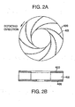
- the spiral pump mechanism portion 4 is provided with a spiral-formed impeller 401 (hereinafter, referred to as "spiral impeller") installed between a pair of rotation boards 400 comprised of the upper rotation board 400 and the lower rotation board 400.
- a rotation fan mechanism body constituted of these rotation boards 400 and the spiral impeller 401 shares the same rotation center axis with the first pump mechanism portion A.
- the rotation fan mechanism body is driven to rotate independently of the rotor shaft 7 of the first pump mechanism portion A.
- the above-described rotation fan mechanism body constituted of the rotation boards 400 and the spiral impeller 401 is fixed by a screw at a rotation shaft of a drive motor 11 equipped independently of the drive motor 9 for rotationally driving the rotor shaft 7 of the first pump mechanism portion A.
- the drive motor 11 is arranged at the lower portion side of the rotation fan mechanism body. Therefore, by controlling the drive motor 11 installed at the lower portion of the above-described rotation fan mechanism body, the spiral pump mechanism portion 4 having such construction is capable of making the pump speed of rotation (the speed of rotation of the rotation fan mechanism body) variable independently of the first pump mechanism A.
- the vacuum pump shown in the figure can be used, for example, as a means for evacuating the process chamber of a semiconductor manufacturing apparatus.
- the gas inlet 5 of the pump case 1 of this vacuum pump is connected to the process chamber side.
- the rotor blades 201 of the turbo molecular pump mechanism portion 2 and the rotor 300 of the thread groove pump mechanism portion 3 and the spiral impeller 401 of the spiral pump mechanism portion 4 rotate.
- the rotor blades 201 of the turbo molecular pump mechanism portion 2 and the rotor 300 of the thread groove pump mechanism portion 3 are constructed integrally with the rotor shaft 7, the rotor blades 201 and the rotor 300 rotate at the speed of rotation equal to that of the rotor shaft 7 due to such construction.
- the spiral impeller 401 is not constructed integrally with the rotor shaft 7, the spiral impeller 401 rotates independently of the rotor shaft 7.
- the inside of the vacuum pump and the inside of the process chamber are close to atmospheric pressure and are in a viscous flow region.
- the resistance of the rotor blades 201 of the turbo molecular pump mechanism portion 2 arises. Therefore, the pump speed of rotation of the first pump mechanism portion A (specifically the speed of rotation of the rotor 200 and the speed of rotation of the rotor 300) does not increase.
- the spiral pump mechanism portion 4 including the independent drive motor (drive motor 11) to rotate rapidly (3000 rpm -50000 rpm), roughing (equal to 50 Torr or less) is executed,
- the gas in the process chamber is caused to flow from the gas inlet 5 of the pump case 1 into the pump case 1 by the suction force of the spiral pump and passes through the spaces between the rotor blades 201 and the stator blades 202 in the turbo molecular pump mechanism portion 2, and flows into the thread groove pump mechanism portion 3 side that is the next lower section.
- the gas thus transferred to the thread groove pump mechanism portion 3 side is sucked up to the side of the spiral pump mechanism portion 4 that is the further next lower section.
- the gas thus sucked up to the spiral pump mechanism portion 4 side is transferred to the gas exhaust port 6 side of the pump case 1 through the exhaust passage C by the rotation of the spiral impeller 401, whereby the gas is exhausted to the outside of the pump therefrom, and is transformed into atmospheric pressure.
- the degree of vacuum in the vacuum pump and the degree of vacuum in the process chamber can be rapidly increased.
- the pump speed of rotation of the first pump mechanism portion A can be rapidly increased.
- the turbo molecular pump mechanism portion 2 due to interaction between the rotating rotor blades 201 and the fixed stator blades 202, the exhausting operation of gas molecule flow is efficiently executed.
- the uppermost rotor blade 201 rotating rapidly imparts downward momentum to the gas molecule group entering from the gas inlet 5.
- the gas molecules with this downward momentum are guided by the stator blade 202 to be transferred to the side of the next lower rotor blade 201.
- the gas molecules are transferred from the gas inlet 5 toward the thread groove pump mechanism portion 3 side for exhaustion.
- the gas molecules transferred to the thread groove pump mechanism portion 3 are compressed to be transformed from an intermediate flow to a viscous flow.
- the gas thus made to be a viscous flow is then transferred to the spiral pump mechanism portion 4 side and is transferred to the gas exhaust port 6 side of the pump case 1 through the exhaust passage C by the rotation of the spiral impeller 401.
- the gas transferred to the gas exhaust port 6 side is exhausted to the outside of the pump therefrom, and is transformed into atmospheric pressure.
- the process pressure in the process chamber is controllable at this vacuum pump side.
- the pump speed of rotation of the first pump mechanism portion A and the pump speed of rotation of the second pump mechanism portion B can be made equal to each other. However, they can also be made different. Utilizing this, for example, while the pump is operating, by setting the pump speed of rotation of the second pump mechanism portion B to be lower than that of the first pump mechanism portion A, the gas exhaust speed of the second pump mechanism portion B decreases and the backing pressure (the pressure of the exhaust side Aout) of the first pump mechanism portion A increases.
- the vacuum pump of the present embodiment is capable of changing the backing pressure of the first pump mechanism portion A and controlling the process pressure in the process chamber utilizing this change of the backing pressure.
- the spiral pump mechanism portion 4 as the second pump mechanism portion B being capable of changing the pump speed of rotation is installed independently of the first pump mechanism portion A.
- the vacuum pump of the present invention is capable of controlling the process pressure with higher responsiveness than that in the conventional method using the conductance valve.
- the vacuum pump of the present invention does not require them.
- the vacuum pump of the present invention does not consume unnecessary gas. As a result, it allows miniaturization and simple construction of the overall apparatus and reduction of the running cost.
- the turbo molecular pump mechanism portion 2 is disposed at the high-vacuum side and the spiral pump mechanism portion 4 is disposed at the atmosphere side and the thread groove pump mechanism portion 3 is disposed between the turbo molecular pump mechanism portion 2 and the spiral pump mechanism portion 4, efficient evacuation from atmosphere to high-vacuum (degree of vacuum: 10 -6 Pa) can be performed with only one vacuum pump of the present invention.
- the first pump mechanism portion A can employ, for example, the construction having only the turbo molecular pump mechanism portion 2 or the construction using a screw pump, other than the above-described compound-type pump construction comprising the turbo molecular pump mechanism portion 2 and the thread groove pump mechanism portion 3.
- the second pump mechanism portion B can employ not only the above-described spiral pump mechanism portion 4 but another pump mechanism having the exhaust function equivalent to that of the spiral pump mechanism portion 4.
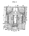
- the spiral impeller 401 may also be composed of two-stage spiral impellers including an upper impeller and a lower impeller. Further, multi-stage structures may also be adopted therefor.
- a division wall 402 is provided between an upper-side spiral impeller 401a and a lower-side spiral impeller 401b. Further, an opening 403 for introducing exhaust gas from the upper-side spiral impeller 401a to the lower-side spiral impeller 401b is formed on one part of the barrier 402.
- a noncontacting-type bearing such as a magnetic bearing, for example, may be adopted other than the above-described ball bearing 8.
- the second pump mechanism portion capable of changing the pump speed of rotation is installed independently of the first pump mechanism portion A. According to this construction of the second pump mechanism portion, by changing the pump speed of rotation in the second pump mechanism portion, the process pressure and the like in the process chamber can be controlled. Therefore, the vacuum pump of the present invention is capable of controlling the process pressure with higher responsiveness than that in the conventional method using the conductance valve. Further, though the conventional system of introducing nitrogen gas requires the gas piping and the flow rate controlling apparatus, the vacuum pump of the present invention does not require them. Further, the vacuum pump of the present invention does not consume unnecessary gas. As a result, it allows miniaturization and simple construction of the overall apparatus and reduction of the running cost.
- a two stage spiral impeller is shown for the second pump mechanism portion B in figure 3.
- a pump mechanism having more than two stages can also be used.
Landscapes
- Engineering & Computer Science (AREA)
- Mechanical Engineering (AREA)
- General Engineering & Computer Science (AREA)
- Non-Positive Displacement Air Blowers (AREA)
- Structures Of Non-Positive Displacement Pumps (AREA)
- Control Of Positive-Displacement Air Blowers (AREA)
Applications Claiming Priority (2)
| Application Number | Priority Date | Filing Date | Title |
|---|---|---|---|
| JP2000367225A JP2002168192A (ja) | 2000-12-01 | 2000-12-01 | 真空ポンプ |
| JP2000367225 | 2000-12-01 |
Publications (1)
| Publication Number | Publication Date |
|---|---|
| EP1213482A1 true EP1213482A1 (de) | 2002-06-12 |
Family
ID=18837688
Family Applications (1)
| Application Number | Title | Priority Date | Filing Date |
|---|---|---|---|
| EP01310055A Withdrawn EP1213482A1 (de) | 2000-12-01 | 2001-11-30 | Vakuumpumpe |
Country Status (4)
| Country | Link |
|---|---|
| US (1) | US20020098092A1 (de) |
| EP (1) | EP1213482A1 (de) |
| JP (1) | JP2002168192A (de) |
| KR (1) | KR20020043445A (de) |
Cited By (5)
| Publication number | Priority date | Publication date | Assignee | Title |
|---|---|---|---|---|
| WO2004055378A1 (en) | 2002-12-17 | 2004-07-01 | The Boc Group Plc | Vacuum pumping arrangement and method of operating same |
| WO2005075827A1 (en) * | 2004-02-03 | 2005-08-18 | The Boc Group Plc | A pumping system |
| EP1746287A1 (de) * | 2005-07-20 | 2007-01-24 | Alcatel | Pumpvorrichtung zum schnellen Evakuiieren eines Behälters mit niedrigem Energieverbrauch |
| EP2843238A3 (de) * | 2013-08-21 | 2015-06-24 | Pfeiffer Vacuum Gmbh | Vakuumpumpe in der unterschiedliche Module entweder mit unterschiedlichen Drehzahlen betrieben werden können oder von unterschiedlichen Gasströmen durchströmt werden können |
| EP3267040A1 (de) * | 2016-07-04 | 2018-01-10 | Pfeiffer Vacuum Gmbh | Turbomolekularpumpe |
Families Citing this family (3)
| Publication number | Priority date | Publication date | Assignee | Title |
|---|---|---|---|---|
| JP6009193B2 (ja) * | 2012-03-30 | 2016-10-19 | 株式会社荏原製作所 | 真空排気装置 |
| DE102014118881A1 (de) * | 2014-12-17 | 2016-06-23 | Pfeiffer Vacuum Gmbh | Vakuumpumpe |
| JP6692635B2 (ja) * | 2015-12-09 | 2020-05-13 | エドワーズ株式会社 | 連結型ネジ溝スペーサ、および真空ポンプ |
Citations (9)
| Publication number | Priority date | Publication date | Assignee | Title |
|---|---|---|---|---|
| US2936107A (en) * | 1956-06-14 | 1960-05-10 | Nat Res Corp | High vacuum device |
| DE3444169A1 (de) * | 1984-12-04 | 1986-06-12 | Loewe Pumpenfabrik GmbH, 2120 Lüneburg | Anordnung zur optimierung des betriebes von vakuumpumpenanlagen |
| US4655688A (en) * | 1984-05-30 | 1987-04-07 | Itt Industries, Inc. | Control for liquid ring vacuum pumps |
| US4699570A (en) * | 1986-03-07 | 1987-10-13 | Itt Industries, Inc | Vacuum pump system |
| US5165864A (en) * | 1989-09-27 | 1992-11-24 | Alcatel Cit | Vacuum pump unit |
| EP0898083A2 (de) * | 1997-08-15 | 1999-02-24 | The BOC Group plc | Vakuum-Pumpsystem |
| US6045331A (en) * | 1998-08-10 | 2000-04-04 | Gehm; William | Fluid pump speed controller |
| EP1043645A1 (de) * | 1999-04-07 | 2000-10-11 | Alcatel | Druckregelvorrichtung für eine Vakuumkammer, und eine mit einer solchen Vorrichtung versehenen Vakuumpumpeinheit |
| US6257835B1 (en) * | 1999-03-22 | 2001-07-10 | Quantachrome Corporation | Dry vacuum pump system for gas sorption analyzer |
-
2000
- 2000-12-01 JP JP2000367225A patent/JP2002168192A/ja not_active Withdrawn
-
2001
- 2001-11-30 US US09/997,814 patent/US20020098092A1/en not_active Abandoned
- 2001-11-30 EP EP01310055A patent/EP1213482A1/de not_active Withdrawn
- 2001-12-01 KR KR1020010075644A patent/KR20020043445A/ko not_active Application Discontinuation
Patent Citations (9)
| Publication number | Priority date | Publication date | Assignee | Title |
|---|---|---|---|---|
| US2936107A (en) * | 1956-06-14 | 1960-05-10 | Nat Res Corp | High vacuum device |
| US4655688A (en) * | 1984-05-30 | 1987-04-07 | Itt Industries, Inc. | Control for liquid ring vacuum pumps |
| DE3444169A1 (de) * | 1984-12-04 | 1986-06-12 | Loewe Pumpenfabrik GmbH, 2120 Lüneburg | Anordnung zur optimierung des betriebes von vakuumpumpenanlagen |
| US4699570A (en) * | 1986-03-07 | 1987-10-13 | Itt Industries, Inc | Vacuum pump system |
| US5165864A (en) * | 1989-09-27 | 1992-11-24 | Alcatel Cit | Vacuum pump unit |
| EP0898083A2 (de) * | 1997-08-15 | 1999-02-24 | The BOC Group plc | Vakuum-Pumpsystem |
| US6045331A (en) * | 1998-08-10 | 2000-04-04 | Gehm; William | Fluid pump speed controller |
| US6257835B1 (en) * | 1999-03-22 | 2001-07-10 | Quantachrome Corporation | Dry vacuum pump system for gas sorption analyzer |
| EP1043645A1 (de) * | 1999-04-07 | 2000-10-11 | Alcatel | Druckregelvorrichtung für eine Vakuumkammer, und eine mit einer solchen Vorrichtung versehenen Vakuumpumpeinheit |
Cited By (14)
| Publication number | Priority date | Publication date | Assignee | Title |
|---|---|---|---|---|
| WO2004055378A1 (en) | 2002-12-17 | 2004-07-01 | The Boc Group Plc | Vacuum pumping arrangement and method of operating same |
| US7999502B2 (en) | 2004-02-03 | 2011-08-16 | Edwards Limited | Pumping system |
| CN100439707C (zh) * | 2004-02-03 | 2008-12-03 | 爱德华兹有限公司 | 一种泵系统 |
| WO2005075827A1 (en) * | 2004-02-03 | 2005-08-18 | The Boc Group Plc | A pumping system |
| KR101143064B1 (ko) * | 2004-02-03 | 2012-05-11 | 에드워즈 리미티드 | 펌핑 시스템 및 펌핑 시스템의 제어 방법 |
| EP1746287A1 (de) * | 2005-07-20 | 2007-01-24 | Alcatel | Pumpvorrichtung zum schnellen Evakuiieren eines Behälters mit niedrigem Energieverbrauch |
| WO2007010170A2 (fr) * | 2005-07-20 | 2007-01-25 | Alcatel Lucent | Pompage rapide d'enceinte avec economie d'energie |
| FR2888894A1 (fr) * | 2005-07-20 | 2007-01-26 | Alcatel Sa | Pompage rapide d'enceinte avec economie d'energie |
| WO2007010170A3 (fr) * | 2005-07-20 | 2007-03-15 | Alcatel Lucent | Pompage rapide d'enceinte avec economie d'energie |
| US7789632B2 (en) | 2005-07-20 | 2010-09-07 | Alcatel | Fast enclosure pumping with power saving |
| CN101213370B (zh) * | 2005-07-20 | 2011-05-18 | 阿尔卡特朗讯公司 | 快速节能的腔抽气 |
| EP2843238A3 (de) * | 2013-08-21 | 2015-06-24 | Pfeiffer Vacuum Gmbh | Vakuumpumpe in der unterschiedliche Module entweder mit unterschiedlichen Drehzahlen betrieben werden können oder von unterschiedlichen Gasströmen durchströmt werden können |
| DE102013216593B4 (de) | 2013-08-21 | 2024-07-11 | Pfeiffer Vacuum Gmbh | Vakuumpumpe und verfahren zum betreiben einer vakuumpumpe |
| EP3267040A1 (de) * | 2016-07-04 | 2018-01-10 | Pfeiffer Vacuum Gmbh | Turbomolekularpumpe |
Also Published As
| Publication number | Publication date |
|---|---|
| KR20020043445A (ko) | 2002-06-10 |
| US20020098092A1 (en) | 2002-07-25 |
| JP2002168192A (ja) | 2002-06-14 |
Similar Documents
| Publication | Publication Date | Title |
|---|---|---|
| JP5053842B2 (ja) | ポンピング装置 | |
| JP4395210B2 (ja) | 真空ポンプの改良 | |
| CN1860301B (zh) | 真空泵 | |
| JP2975008B2 (ja) | 自由ロータ | |
| US5810557A (en) | Fan wheel for an inline centrifugal fan | |
| JPH037039B2 (de) | ||
| US6672827B2 (en) | Vacuum pump | |
| EP1213482A1 (de) | Vakuumpumpe | |
| JP2003515037A (ja) | 半径方向流ターボ分子真空ポンプ | |
| JP2001027195A (ja) | 真空ポンプ | |
| JP5319118B2 (ja) | 真空ポンプ | |
| JP2018516338A (ja) | 真空ポンプ | |
| JP2010540824A (ja) | 2つのヘリカルロータを備える真空ポンプ | |
| JPS62113887A (ja) | 真空ポンプ | |
| JP2007507658A (ja) | 真空ポンプ | |
| JP2002310092A (ja) | 真空ポンプ | |
| EP1108145B1 (de) | Selbstfahrende vakuumpumpe | |
| US20070081893A1 (en) | Pump apparatus for semiconductor processing | |
| JP2001090690A (ja) | 真空ポンプ | |
| JPH06249187A (ja) | 真空ポンプおよびその駆動方法 | |
| CN114901951A (zh) | 真空泵、用于抽空半导体处理腔室的真空泵组以及抽空半导体处理腔室的方法 | |
| JP3233364U (ja) | 真空システム | |
| JPH02136595A (ja) | 真空ポンプ | |
| JPH02264196A (ja) | ターボ真空ポンプ | |
| KR20010011629A (ko) | 터보 압축기의 디퓨져 구조 |
Legal Events
| Date | Code | Title | Description |
|---|---|---|---|
| PUAI | Public reference made under article 153(3) epc to a published international application that has entered the european phase |
Free format text: ORIGINAL CODE: 0009012 |
|
| AK | Designated contracting states |
Kind code of ref document: A1 Designated state(s): AT BE CH CY DE DK ES FI FR GB GR IE IT LI LU MC NL PT SE TR |
|
| AX | Request for extension of the european patent |
Free format text: AL;LT;LV;MK;RO;SI |
|
| 17P | Request for examination filed |
Effective date: 20021105 |
|
| AKX | Designation fees paid |
Designated state(s): DE FR GB |
|
| RAP1 | Party data changed (applicant data changed or rights of an application transferred) |
Owner name: BOC EDWARDS JAPAN LIMITED |
|
| STAA | Information on the status of an ep patent application or granted ep patent |
Free format text: STATUS: THE APPLICATION IS DEEMED TO BE WITHDRAWN |
|
| 18D | Application deemed to be withdrawn |
Effective date: 20050601 |