EP1213217B1 - Bicycle hub - Google Patents
Bicycle hub Download PDFInfo
- Publication number
- EP1213217B1 EP1213217B1 EP01125082A EP01125082A EP1213217B1 EP 1213217 B1 EP1213217 B1 EP 1213217B1 EP 01125082 A EP01125082 A EP 01125082A EP 01125082 A EP01125082 A EP 01125082A EP 1213217 B1 EP1213217 B1 EP 1213217B1
- Authority
- EP
- European Patent Office
- Prior art keywords
- hub
- bicycle hub
- bicycle
- hub according
- projections
- Prior art date
- Legal status (The legal status is an assumption and is not a legal conclusion. Google has not performed a legal analysis and makes no representation as to the accuracy of the status listed.)
- Expired - Lifetime
Links
- 230000000295 complement effect Effects 0.000 claims description 12
- 230000001154 acute effect Effects 0.000 claims description 6
- 238000000926 separation method Methods 0.000 claims description 5
- CVOFKRWYWCSDMA-UHFFFAOYSA-N 2-chloro-n-(2,6-diethylphenyl)-n-(methoxymethyl)acetamide;2,6-dinitro-n,n-dipropyl-4-(trifluoromethyl)aniline Chemical compound CCC1=CC=CC(CC)=C1N(COC)C(=O)CCl.CCCN(CCC)C1=C([N+]([O-])=O)C=C(C(F)(F)F)C=C1[N+]([O-])=O CVOFKRWYWCSDMA-UHFFFAOYSA-N 0.000 claims 1
- 230000013011 mating Effects 0.000 claims 1
- 230000036961 partial effect Effects 0.000 description 9
- 239000000463 material Substances 0.000 description 8
- 229910000831 Steel Inorganic materials 0.000 description 7
- 239000010959 steel Substances 0.000 description 7
- RTAQQCXQSZGOHL-UHFFFAOYSA-N Titanium Chemical compound [Ti] RTAQQCXQSZGOHL-UHFFFAOYSA-N 0.000 description 6
- XAGFODPZIPBFFR-UHFFFAOYSA-N aluminium Chemical compound [Al] XAGFODPZIPBFFR-UHFFFAOYSA-N 0.000 description 6
- 229910052782 aluminium Inorganic materials 0.000 description 6
- 230000000712 assembly Effects 0.000 description 6
- 238000000429 assembly Methods 0.000 description 6
- 239000007769 metal material Substances 0.000 description 6
- 229910052719 titanium Inorganic materials 0.000 description 6
- 239000010936 titanium Substances 0.000 description 6
- 230000008878 coupling Effects 0.000 description 5
- 238000010168 coupling process Methods 0.000 description 5
- 238000005859 coupling reaction Methods 0.000 description 5
- 230000000717 retained effect Effects 0.000 description 2
- 230000002441 reversible effect Effects 0.000 description 2
- 230000002860 competitive effect Effects 0.000 description 1
- 230000000670 limiting effect Effects 0.000 description 1
- 238000004519 manufacturing process Methods 0.000 description 1
- 238000000034 method Methods 0.000 description 1
- 238000012986 modification Methods 0.000 description 1
- 230000004048 modification Effects 0.000 description 1
- 125000006850 spacer group Chemical group 0.000 description 1
Images


Classifications
-
- B—PERFORMING OPERATIONS; TRANSPORTING
- B62—LAND VEHICLES FOR TRAVELLING OTHERWISE THAN ON RAILS
- B62M—RIDER PROPULSION OF WHEELED VEHICLES OR SLEDGES; POWERED PROPULSION OF SLEDGES OR SINGLE-TRACK CYCLES; TRANSMISSIONS SPECIALLY ADAPTED FOR SUCH VEHICLES
- B62M9/00—Transmissions characterised by use of an endless chain, belt, or the like
- B62M9/04—Transmissions characterised by use of an endless chain, belt, or the like of changeable ratio
- B62M9/06—Transmissions characterised by use of an endless chain, belt, or the like of changeable ratio using a single chain, belt, or the like
- B62M9/10—Transmissions characterised by use of an endless chain, belt, or the like of changeable ratio using a single chain, belt, or the like involving different-sized wheels, e.g. rear sprocket chain wheels selectively engaged by the chain, belt, or the like
-
- B—PERFORMING OPERATIONS; TRANSPORTING
- B60—VEHICLES IN GENERAL
- B60B—VEHICLE WHEELS; CASTORS; AXLES FOR WHEELS OR CASTORS; INCREASING WHEEL ADHESION
- B60B27/00—Hubs
- B60B27/0005—Hubs with ball bearings
-
- B—PERFORMING OPERATIONS; TRANSPORTING
- B60—VEHICLES IN GENERAL
- B60B—VEHICLE WHEELS; CASTORS; AXLES FOR WHEELS OR CASTORS; INCREASING WHEEL ADHESION
- B60B27/00—Hubs
- B60B27/0078—Hubs characterised by the fixation of bearings
-
- B—PERFORMING OPERATIONS; TRANSPORTING
- B60—VEHICLES IN GENERAL
- B60B—VEHICLE WHEELS; CASTORS; AXLES FOR WHEELS OR CASTORS; INCREASING WHEEL ADHESION
- B60B27/00—Hubs
- B60B27/02—Hubs adapted to be rotatably arranged on axle
- B60B27/023—Hubs adapted to be rotatably arranged on axle specially adapted for bicycles
- B60B27/026—Hubs adapted to be rotatably arranged on axle specially adapted for bicycles comprising quick release devices
-
- B—PERFORMING OPERATIONS; TRANSPORTING
- B60—VEHICLES IN GENERAL
- B60B—VEHICLE WHEELS; CASTORS; AXLES FOR WHEELS OR CASTORS; INCREASING WHEEL ADHESION
- B60B27/00—Hubs
- B60B27/02—Hubs adapted to be rotatably arranged on axle
- B60B27/04—Hubs adapted to be rotatably arranged on axle housing driving means, e.g. sprockets
- B60B27/047—Hubs adapted to be rotatably arranged on axle housing driving means, e.g. sprockets comprising a freewheel mechanisms
-
- B—PERFORMING OPERATIONS; TRANSPORTING
- B62—LAND VEHICLES FOR TRAVELLING OTHERWISE THAN ON RAILS
- B62K—CYCLES; CYCLE FRAMES; CYCLE STEERING DEVICES; RIDER-OPERATED TERMINAL CONTROLS SPECIALLY ADAPTED FOR CYCLES; CYCLE AXLE SUSPENSIONS; CYCLE SIDE-CARS, FORECARS, OR THE LIKE
- B62K25/00—Axle suspensions
- B62K25/02—Axle suspensions for mounting axles rigidly on cycle frame or fork, e.g. adjustably
Description
- This invention generally relates to a bicycle hub with a detachable freewheel. More specifically, the present invention relates a bicycle hub with a tight connection ratchet between the hub body and sprocket support member, which allows separation of the hub body from the sprocket support member.
- Bicycling is becoming an increasingly popular form of recreation as well as a means of transportation. Moreover, bicycling has become a very popular competitive sport. Whether the bicycle is used for recreation, transportation or competition, the bicycle industry is constantly improving their components. One particular component of the bicycle which has been extensively redesigned over the past years is the freewheel of the rear bicycle hub.
- Specifically, most bicycles have several speeds. One popular form of drive train for a bicycle includes utilizing a plurality of sprockets that are mounted on the hub of the rear bicycle wheel. During pedaling, the bicycle chain engages one of the rear sprockets to rotate the rear wheel. When bicycle rider stops pedaling, the rear wheel should be able to continue to rotate while the sprockets remain stationary. Accordingly, the rear hub is provided with a freewheel that has a one-way clutch.
- With an increased number of speeds provided by a derailleur of a bicycle today, a multi-step sprocket wheel unit for the rear wheel includes an increased number of sprockets which is now five to seven. There are demands for a simplified mounting structure and easy mounting method.
- Freewheels used to transmit a driving force to the rear bicycle wheel in one rotation direction only are usually mounted on the rear hub of a bicycle. Freewheels are used so that the bicycle can advance freely without any rotation of the pedals. Freewheels include boss type freewheels which are mounted on the boss of the rear hub by being screwed onto the rear hub, and freehub type freewheels which are fastened to the rear hub as integral parts of the rear hub. Both types of freewheels are equipped with an outer tubular part, an inner tubular part which is installed radially inwardly of the outer tubular part so that the inner tubular part is free to rotate relative to the outer cylinder part, and a one-way clutch which is installed between the outer tubular part and inner tubular part for transmitting the driving force from the outer tubular part to the inner tubular part in one rotational direction only. The outer tubular part has a plurality of gears mounted thereon, while the inner tubular part is usually mounted on the rear hub of the bicycle.
- Splines are formed between the sprocket wheels and boss to prohibit relative rotation therebetween positively. Since this unit is used for the rear wheel of a bicycle, drive must be transmitted between the rear wheel axle and boss through a one-way mechanism. For this purpose, the boss is formed as an outer race of a one-way clutch, and the one-way clutch and inner race are disposed on an inner periphery of the boss.
- As the number of rear gears or sprockets have increased over the years, the freewheel has become larger and heavier. Moreover, with the increased number of years or sprockets, a wider range of torque is being applied from the sprockets to the freewheel. An example of prior art bicycle hub is shown in document FRA 2776612.
- In view of the above, there exists a need for a bicycle hub with a detachable freewheel which overcomes the above mentioned problems in the prior art. This invention addresses this need in the prior art as well as other needs, which will become apparent to those skilled in the art from this disclosure.
- One object of the present invention is to provide a bicycle hub with a tight connection ratchet that has a simplified structure.
- Another object of the present invention is to provide a bicycle hub with a tight connection ratchet that allows simplified mounting.
- Another object of the present invention is to provide a bicycle hub with a tight connection ratchet for detaching a hub body from a sprocket support member that is relatively simple and inexpensive to manufacture and assemble.
- The foregoing objects can basically be attained by providing a bicycle hub, as in claim 1.
- These and other objects, features, aspects and advantages of the present invention will become apparent to those skilled in the art from the following detailed description, which, taken in conjunction with the annexed drawings, discloses a preferred embodiment of the present invention.
- Referring now to the attached drawings which form a part of this original disclosure:
- Figure 1 is a side elevational view of a conventional bicycle with a rear hub in accordance with the present invention;
- Figure 2 is an enlarged, partially exploded perspective view of the rear bicycle hub illustrated in Figure 1;
- Figure 3 is an enlarged, partially exploded, partial reverse perspective view of the hub illustrated in Figure 2 with portions broken away to show the sprocket support member and engagement member prior to complete engagement;
- Figure 4 is an enlarged, partial reverse perspective view of portions of the rear hub illustrated in Figures 2 and 3, with portions broken away to show engagement of the sprocket support member with the engagement member;
- Figure 5 is an enlarged, partial cross-sectional view of the assembled rear hub illustrated in Figures 1-4;
- Figure 6 is a partial cross-sectional view of the rear hub illustrated in Figures 1-5 with the sprocket support member detached from the hub body;
- Figure 7 is an enlarged, partial cross-sectional view of the sprocket support member illustrated in Figures 2-6;
- Figure 8 is an end elevational view of the sprocket support member illustrated in Figure 7;
- Figure 9 is an opposite end elevational view of the sprocket support member illustrated in Figures 7 and 8;
- Figure 10 is an enlarged, partial cross-sectional view of the engagement member of the hub body of the rear hub illustrated in Figures 2-6;
- Figure 11 is an end elevational view of the engagement member illustrated in Figure 10;
- Figure 12 is an opposite end elevational view of the engagement member illustrated in Figures 10 and 11;
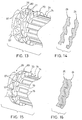
- Figure 13 is an enlarged, partial perspective view of the engagement member and sprocket support member illustrated in Figures 2-12 prior to engagement between the sprocket support member and the engagement member;
- Figure 14 is a diagrammatic cross-sectional view of the projections and recesses of the sprocket support member and engagement member illustrated in Figure 13;
- Figure 15 is an enlarged, partial perspective view of the sprocket support member and engagement member illustrated in Figures 2-12 showing an intermediate engagement position;
- Figure 16 is a diagrammatic cross-sectional view of the projections and recesses of the sprocket support member and engagement member illustrated in Figure 15;
- Figure 17 is an enlarged, partial perspective view of the sprocket support member and engagement member illustrated in Figures 2-12 showing an engaged position;
- Figure 18 is a diagrammatic cross-sectional view of the projections and recesses of the sprocket support member and engagement member illustrated in Figure 17; and
- Figure 19 is an enlarged, diagrammatic cross-sectional view of one projection of the sprocket support member and one recess of the engagement member prior to engagement with each other.
- Referring initially to Figure 1, a
bicycle 10 is illustrated with a rear hub in accordance with the present invention installed thereon as discussed below.Bicycle 10 has aframe 12 with afront fork 13 movably coupled thereto and arear fork 15 fixedly coupled thereto. Arear wheel 16 is rotatably coupled torear fork 15 via arear hub 18. Afront wheel 14 is rotatably coupled tofront fork 13 via afront hub 17. A seat is adjustably coupled toframe 12 and ahandlebar 11 is coupled tofront fork 13 for turningfront wheel 14. Adrive train 19 is coupled toframe 12 for propellingbicycle 10.Drive train 19 basically includes a front set ofsprockets 19a, a pair ofcrank arms 19b withpedals 19c, adrive chain 19d and a set ofrear sprockets 19e.Front sprockets 19a are rotatably coupled to frame 12 via a bottom bracket (not shown).Rear sprockets 19e are coupled torear hub 18 ofrear wheel 16 in a relatively conventional manner. - Since the various components of
bicycle 10 are well known in the art, these parts will not be discussed or illustrated in detail herein, except as they are modified in accordance with the present invention. More specifically, components ofbicycle 10 will not be discussed or illustrated herein, except as they relate to rearhub 18. Moreover, it will be apparent to those skilled in the art from this disclosure that various conventional bicycle parts such as brakes, derailleurs, additional sprockets, etc., which are not illustrated and/or discussed herein, can be used in conjunction with the present invention. - Referring now to Figures 2-6,
rear hub 18 basically includes ahub axle 20, ahub body 22, and asprocket member 24.Hub axle 20 is rotatably supported within an interior passageway ofhub body 22 and extends axially from both ends ofhub body 22.Hub body 22 has an engagement member 26 (i.e. an engagement portion) coupled thereto. The engagement member is non-rotatably coupled tosprocket support member 24 whenrear hub 18 is assembled.Hub axle 20 is preferably formed of two parts releasably coupled together sohub body 22 can separated fromsprocket support member 24.Engagement member 26 is preferably coupled tohub body 22 via a one way clutch such thatengagement member 26 is freely rotatable relative tohub body 26 in only one direction.Hub body 22 rotates withengagement member 26 whenengagement member 26 is rotated in the opposite direction. -
Hub body 22 is preferably mounted on one part ofhub axle 20 whilesprocket support member 26 is preferably freely rotatably mounted on the other part ofhub axle 20. The two parts ofhub axle 20 are preferably threadedly coupled together to allow release ofsprocket support member 24 fromhub body 22 without removingsprocket support member 24 fromrear fork 15. In the illustrated embodiment, thesprocket support member 24,engagement member 26, and a one-way clutch 28 form parts of the freewheel. Of course, it will be apparent to those skilled in the art from this disclosure that the present invention can be used with hubs that do not include a one way clutch (i.e. freewheel) if needed and\or desired. Moreover, the term "sprocket support member" is used herein to refer to a portion of the hub that has at least one sprocket directly or indirectly supported thereon. - Referring still to Figures 2-6,
hub axle 20 basically includes afirst portion 30 and asecond portion 32 threadedly coupled tofirst portion 30 via a threaded connection. Preferably,first portion 30 is rotatably supported within an interior passageway ofhub body 22 andsprocket support member 24 is mounted onsecond portion 32 ofhub axle 20. Moreover,first portion 30 is preferably threadedly coupled tosecond portion 32 such thatfirst portion 30 can be separated fromsecond portion 32. Preferably,hub axle 20 has a diameter large enough to provide enough strength forseparable hub axle 20. -
First portion 30 ofhub axle 20 is preferably an elongate cylindrical member formed of lightweight, rigid metallic material, such as cast aluminum, titanium, or steel. Of course,first portion 30 could be constructed of any suitable material as needed and/or desired. Moreover,first portion 30 preferably has a substantially constant, circular cross-section.First portion 30 ofhub axle 20 basically includes afirst end section 34, asecond end section 36 axially spaced fromfirst end section 34 and acentral section 38 extending betweenfirst end section 34 andsecond end section 36. -
First end section 34 is preferably provided with external clockwise threads for releasably couplingfirst portion 30 tosecond portion 32. Moreover,first end section 34 preferably has a retainingring 31 releasably mounted thereon in a conventional manner adjacentcentral section 38. Retainingring 31 is mounted onfirst portion 30 afterfirst portion 30 is mounted withinhub body 22 such thatfirst portion 32 is retained within the interior passageway of hub body. Retainingring 31 is preferably either an internally threaded ring member or a C-clamp. Of course, retainingring 31 can have various configurations as needed and/or desired. -
Second end section 36 is configured such thatsecond end section 36 can be provided with aquick release mechanism 37 coupled thereto in a conventional manner. Thusquick release mechanism 37 is used to couple one side of therear hub 18 to therear fork 15 in a relatively conventional manner as discussed in more detail below. -
Central section 38 is a cylindrical rod-shaped section extending betweenfirst end section 34 andsecond end section 36.Central section 38 ofhub axle 20 is sized and configured to be slidably and freely rotatably received within a portion ofhub body 22 in a relatively conventional manner. - Preferably,
second portion 32 ofhub axle 20 is a step-shaped cylindrical member having a varying cross-section for supportingfreewheel 24, as best seen in Figures 5 and 6. Moreover,second portion 32 preferably has a minimum diameter to provide adequate strength forseparable hub axle 20 and is preferably formed of lightweight, rigid metallic material, such as cast aluminum, titanium, or steel. Of course,second portion 32 could be constructed of any suitable material as needed and/or desired.Second portion 32 basically includes afirst end section 40, asecond end section 42 axially spaced fromfirst end section 40, a central steppedsection 44 extending betweenfirst end section 40 andsecond end section 42 and a throughbore 46 extending throughsecond portion 32. -
First end section 40 is preferably provided with external threads for receiving anut 41.Nut 41 is threadedly coupled tofirst end section 40 for coupling one side ofrear hub 18 torear fork 15 in a relatively conventional manner. Moreover,first end section 40 preferably has the smaller or minimum external diameter ofsecond portion 32 andsecond end section 42 has the larger external diameter ofsecond portion 32. -
Second end section 42 has anexternal surface 43 sized and configured such thatsprocket support member 24 can be freely rotatably mounted thereon. More specifically,external surface 43 includes a pair of annular, curved bearing recesses configured to receive a plurality of ball bearings orspherical balls 45 in order to freely rotatably mountsprocket support member 24 onsecond portion 32 ofhub axle 20 in a conventional manner. - Through bore 46 basically includes an
end section 47a, a threadedsection 47b and acylindrical center section 47c extending betweenend section 47a and threadedsection 47b.End section 47a of throughbore 46 is located withinfirst end section 40 and preferably has a hexagonal cross-section for non-rotatably receiving conventional hexagonal wrench. Thus,second portion 32 ofhub axle 20 can be prevented from rotating by inserting a hexagonal wrench intoend section 47a. Threadedsection 47b is located withinsecond end section 42 ofsecond portion 32 ofhub axle 20. Threadedsection 47b is sized and configured to threadedly receive threadedfirst end section 34 offirst portion 30 such that first andsecond portions hub axle 20 can be threadedly coupled together. Accordingly, whenfirst portion 30 is threadedly coupled tosecond portion 32, first andsecond portions rear hub 18. - Referring still to Figures 2-6,
hub body 22 basically includes an outertubular portion 50, a tubularinner sleeve portion 52 and a pair of bearingassemblies 54 rotatably couplinginner sleeve portion 52 and outertubular portion 50 together in a freely rotatable manner.First portion 30 ofhub axle 20 is preferably rotatably supported withininner sleeve portion 52 within the interior passageway of outertubular portion 50.Hub body 22 also preferably includes the one way clutch and an engagement portion as will be discussed in more detail below. - Outer
tubular portion 50 is a tubular member with varying internal and external circular cross-sections, as best seen in Figures 5 and 6. Moreover, outertubular portion 50 is preferably formed of lightweight, rigid metallic material, such as cast aluminum, titanium, or steel. Of course, outertubular portion 50 could be constructed of any suitable material as needed and/or desired. Outertubular portion 50 includes a pair of annular spoke mountingflanges 51 axially spaced from each other forcoupling hub body 22 to the rim ofwheel 16 in a conventional manner. Spoke mountingflanges 51 extend from opposite ends of outertubular portion 50 and are adjacent free ends of outertubular portion 50. A plurality of spokes are coupled to mountingflanges 51 to securehub body 22 towheel 16 in a conventional manner. - Outer
tubular portion 50 also preferably includes a pair of abutment surfaces or abutment shoulders 53 facing in opposite directions for securingbearing assemblies 54 against longitudinal movement (i.e. axial) movement towards each other. Outertubular portion 50 also preferably includes arecess 55 at one end and a brakedisc mounting portion 57 at the opposite end.Recess 55 is preferably a threaded recess with clockwise internal threads sized and configured to receive a portion of the one-way clutch 28 therein. Brakedisc mounting portion 57 preferably has a plurality of threaded attachment holes for coupling a brake disc (not shown) thereto in a conventional manner. Of course it will be apparent to those skilled in the art from this disclosure thathub 18 could be designed for use with conventional rim brakes as need and/or desired. For example, brakedisc mounting portion 57 could be eliminated (i.e. the threaded mounting holes could be eliminated and the shape of outertubular portion 50 could be modified). -
Recess 55 is preferably a stepped recess with internal threads for receiving part of one-way clutch 28. The outer tubular portion is coupled toengagement member 26 via one-way clutch 28 in a relatively conventional manner, as will be discussed in more detail below. Thus,engagement member 26 is preferably freely rotatable in a first rotational direction relative to outertubular portion 50, and engages outertubular portion 50 to rotate with outertubular portion 50 in the second rotational direction via one-way clutch 28, as will also be discussed in more detail below. -
Bearing assemblies 54 are relatively conventional, and basically each include an inner race, a plurality of bearings or spherical steel balls and an outer race. Each outer race contacts an internal surface of outertubular portion 50 and anabutment shoulder 53 of outertubular portion 50 to securebearing assemblies 54 against axial movement, as discussed above. Each inner race preferably contacts an external surface ofinner sleeve portion 52 such thatinner sleeve portion 52 is freely rotatable relative to outertubular portion 50. - Referring still to Figures 2-6,
inner sleeve portion 52 is preferably an elongated tubular member with a step shaped circular cross-section as best seen in Figures 5 and 6. Additionally,inner sleeve portion 52 is preferably formed of lightweight, rigid metallic material, such as cast aluminum, titanium or steel. Of course,inner sleeve portion 52 could be constructed of any suitable material as needed and/or desired. Innertubular portion 52 basically includes a supportingsection 66, a steppedtubular end section 68 or enlarged tubular section) extending from supportingsection 66 and a throughbore 70 extending through supportingsection 66 and steppedsection 68. - Supporting
section 66 ofinner sleeve portion 52 has a partially threaded external surface configured to support bearingassemblies 54 such that outertubular portion 50 is freely rotatable relative toinner sleeve portion 52. Steppedtubular section 68 is sized and configured to retain one of thebearing assemblies 54 against axial movement. Moreover, steppedtubular section 68 has an external surface configured such thatengagement member 26 is freely rotatable aboutinner sleeve portion 52 and axially retained inrecess 55 ofhub body 22. More specifically, steppedsection 68 preferably has an external diameter smaller than the internal diameter ofengagement member 26. Moreover, steppedsection 68 is sized and configured such that aclutch retaining member 69 can be coupled thereto to prevent removal of one-way clutch 28 fromrecess 55. - Through bore 70 includes a recessed section adjacent
second portion 32 ofhub axle 20 whenrear hub 18 is assembled. The recessed section of throughbore 70 allows threaded first end section 34 (with retainingring 31 mounted thereon) offirst portion 30 to be retracted within throughbore 70 so thathub body 22 can be removed fromsprocket support member 24. The recessed section of throughbore 70 forms an internal abutment shoulder that prevents removal offirst portion 30 with retainingring 31. Through bore ofinner sleeve portion 50 is preferably a cylindrical through bore slightly larger than the diameter offirst portion 30 ofhub axle 20 such thatfirst portion 30 is freely rotatably and slidable within throughbore 70. Thus threadedfirst end section 34 offirst portion 30 can be retracted into throughbore 70. - Referring now to Figures 2-9,
sprocket support member 24 will now be discussed in more detail.Sprocket support member 24 is preferably formed as a one-piece, unitary member constructed of a substantially hard, rigid material. For example,sprocket support member 24 can be constructed of a lightweight metallic material such as aluminum or titanium or a slightly heavier material such as steel.Sprocket support member 24 is a tubular member and basically includes anengagement portion 70, asprocket supporting section 72 and throughbore 74 extending axially therethrough. - In the preferred embodiment,
sprocket support member 24 has sevensprockets 19e non-rotatably mounted to the external surface ofsprocket support member 24. The spacing betweensprockets 19e are maintained by a plurality of spacers in a conventional manner. Of course, it will be apparent to those skilled in the art from this disclosure thatsprocket support member 24 could have more/fewer sprockets 19e mounted thereon as needed and/or desired. In any case,sprocket support member 24 has at least one sprocket directly or indirectly supported thereon. -
Engagement portion 70 includes an annularaxially facing surface 76 and a plurality of axially facingprojections 77 extending from axially facingsurface 76.Sprocket supporting section 72 includes a plurality ofaxial splines 78 extending around its periphery for non-rotatably securingsprockets 19e thereon in a conventional manner. Each of thesplines 78 has anabutment stopper 79 extending radially outwardly therefrom. Theabutment stoppers 79 limit axial movement of thesprockets 19e on the external surface ofsprocket support member 24 in a conventional manner. - The axially facing
annular surface 76 andprojections 77 together form a meshing surface to non-rotatably engage a meshing surface ofhub body 22, as discussed in more detail below. More specifically, theprojections 77 and annularaxially facing surface 76 are sized and configured to non-rotatably engage a meshing surface ofengagement member 26. The meshing surfaces are so dimensioned to overlap in a circumferential direction such that axial separation ofengagement member 26 andsprocket support member 24 is prevented unless relative rotation occurs betweensprocket support member 24 andengagement member 26, as also discussed below in more detail. - Referring still to Figures 2-9,
projections 77 are circumferentially arranged around annularaxially facing surface 76 and equally spaced from each other. Moreover, eachprojection 77 is preferably formed of a firstangled surface 77a, a secondangled surface 77b and anaxial end surface 77c. The first and secondangled surfaces projection 77 are circumferentially spaced from each other and connected to each other byaxial end surface 77c. Eachaxial end surface 77c is preferably substantially parallel to the annularaxially facing surface 76. Moreover, each axial end surface is preferably axially spaced from axially facing surface 76 a distance X of approximately 2.5mm, as seen in Figure 19. In other words,projections 77 preferably have an axial thickness X of approximately 2.5mm. Accordingly,projections 77 can be considered low profile projections. However, despite the so-called low profile ofprojections 77, positive non-rotatable engagement betweenengagement member 36 andsprocket support member 24 can be obtained. - Each
projection 77 also preferably includes an innercircumferentially extending surface 77d and an outercircumferentially extending surface 77e. Inner circumferentially extendingsurface 77d is preferably substantially perpendicular to theaxially facing surface 76. Outer circumferentially extendingsurface 77e is also preferably substantially perpendicular to axially facingsurface 76 but includes a curved intersection surface betweenaxial end surface 77c and outer circumferentially extendingsurface 77e. Inner and outer circumferentially extendingsurfaces - The structure of the first and second
angled surfaces projections 77 will now be discussed in more detail. Preferably, firstangled surface 77a forms an acute angle A withaxial surface 76, as seen in Figure 19. Moreover, secondangled surface 77b preferably forms an obtuse angle B withaxial surface 76, as also seen in Figure 19. Moreover, first and secondangled surfaces projection 77 are preferably arranged in the same orientation in the circumferential direction aroundengagement portion 70 ofsprocket support member 24. In other words, firstangled surfaces 77a are spaced circumferentially from respective secondangled surface 77b ofadjacent projections 77. Preferably the acute angle A between each firstangled surface 77a andaxial surface 76 is approximately 80 degrees, while the obtuse angle B formed between each secondangled surface 77b andaxial surface 76 is approximately 150 degrees. Thus,projections 77 extend slightly in a circumferential direction. - Referring to Figures 2-6 and 10-12,
engagement member 26 will now be discussed in more detail.Engagement member 26 is preferably formed as a one-piece unitary member constructed of substantially hard, rigid material. For example,Engagement member 26 can be constructed of a lightweight metallic material such as aluminum or titanium or a slightly heavier material such as steel.Engagement member 26 is a tubular member and basically includes anengagement portion 80, atubular portion 82 and a throughbore 84.Tubular portion 82 extends axially fromengagement portion 80 and forms part of one-way clutch 28, as discussed in more detail below. Through bore 84 is sized and configured such that innertubular sleeve portion 52 andfirst portion 30 ofhub axle 20 are freely rotatable therein. -
Engagement portion 80 basically includes an annularaxially facing surface 86 with a plurality of axially extendingrecesses 87 formed therein.Axially facing surface 86 and recesses 87 form a meshing surface sized and configured to mate with the meshing surface formed byprojection 77 and axially facingsurface 76 ofsprocket support member 24. More specifically, the meshing surfaces (ofengagement member 26 and sprocket support member 24) are so dimensioned to overlap in a circumferential direction such that axial separation ofengagement member 26 andsprocket support member 24 is prevented unless relative rotation occurs betweensprocket support member 24 andengagement member 26. -
Recesses 87 are circumferentially arranged around annularaxially facing surface 86 and equally spaced from each other. Moreover, eachrecess 87 is preferably formed of a complementary firstangled surface 87a, a complementary secondangled surface 87b and a complementaryaxial end surface 87c. The first and secondangled surfaces recess 87 are circumferentially spaced from each other and connected to each other byaxial end surface 87c. Eachaxial end surface 87c is preferably substantially parallel to the annularaxially facing surface 86. Moreover, eachaxial end surface 87c is preferably axially spaced from axially facing surface 86 a distance Y of approximately 2.5mm, as seen in Figure 19. In other words, recesses 87 preferably have an axial depth Y of approximately 2.5mm. Accordingly, recesses 87 can be considered low profile recesses. However, despite the so-called low profile ofprojections 77 and recesses 87, positive non-rotatable engagement betweenengagement member 26 andsprocket support member 24 can be obtained. - Each
recess 87 also preferably includes a thirdangled surface 87d extending radially inwardly from complementaryaxial end surface 87c to annularaxially facing surface 86. In other words, recesses 87 do not include a complementary inner circumferentially extending surface designed to mate withsurface 77d ofprojections 77. Moreover, thirdangled surface 87d extends circumferentially between the first and secondangled surfaces recess 77 has a maximum radial width T larger than radial width S of eachprojection 77 and a minimum radial width substantially equal to the radial width S of eachprojection 77. In other words, eachprojection 77 has a substantially constant radial width, whilerecesses 87 have a varying radial width due to the structure of the thirdangled surfaces 87d. - Third
angled surfaces 87d act as ramp surfaces (i.e. inclined planes) for guidingprojections 77 whensprocket support member 24 is moved in a transverse direction relative tohub body 22. However, recesses 87 have substantially an identical cross section in the circumferential direction to the cross section ofprojections 77 in the circumferential direction as seen in Figure 19. Therefore,engagement member 26 andsprocket support member 24 rotate together in either direction whenprojections 77 are completely received in recesses 87 (provided axial separation is limited), as discussed in more detail below. - In the illustrated embodiment,
axial surface 86 and recesses 87 can be considered a first meshing surface, whileaxial surface 76 andprojections 77 can be considered a second meshing surface. In other words,engagement member 26 has a first meshing surface facing in a first axial direction, andsprocket support member 24 has a second meshing surface facing in a second axial direction opposite the first axial direction. - Referring to Figures 7-12, the first and second
angled surfaces recesses 87 are complementary to first and secondangled surfaces projections 77 as mentioned above. Additionally, firstangled surfaces angled surfaces angled surfaces angled surfaces 87a are arranged on a clockwise side ofrecesses 87 as seen in Figure 12, whileangled surfaces 77a are arranged on a counter-clockwise side ofprojections 77 as seen in Figure 8. However, Figures 8 and 12 are opposite end elevational views ofsprocket support member 24 andengagement member 26, respectively. Thus, angled surfaces 77a and 87a contact each other whensprocket support member 24 is engaged withengagement member 26. - Referring to Figures 13-18, when sprocket support member is rotated in a positive direction (i.e. clockwise direction) relative to
recesses 87, a tight connection in the clockwise direction can be obtained as seen in Figures 17 and 18. This clockwise direction can be considered a positive rotational direction of sprocket support member relative to hub body 22 (i.e. positive rotation of drive train 19). One way clutch 28 is oriented such that whenengagement member 26 is rotated in the positive direction, outertubular portion 50 ofhub body 22 will also be rotated in the positive direction. On the other hand, ifsprocket support member 24 is rotated in the negative direction (i.e. counterclockwise direction) as viewed in Figures 17 and 18,engagement member 26 will be freely rotatable in the negative direction relative to outertubular portion 50. Thus,engagement member 26 will also rotate with sprocket support member in the negative direction. - One-way clutch 28 is relatively conventional and includes a pawl spring and three pawls (not shown) located 120° apart from each other on the pawl spring. One-way clutch 28 also includes portions of
hub body 22 andengagement member 26. In particular, one-way clutch 28 includes an annular groove and three pawl seats ofengagement member 26 and ratchet teeth of anouter tubular member 82. Outertubular member 82 is threadedly coupled withinrecess 55 of outertubular member 50 ofhub body 22. The pawl spring is located within groove for securing the pawls in the pawl seats in a conventional manner. The pawls normally engage the ratchet teeth such thathub body 22 can rotate in one direction about the longitudinal axis but cannot rotate in the other direction in a conventional manner. - Assembly and operation of
rear hub 18 will now be discussed in more detail.Hub body 22 is basically assembled withfirst portion 30 ofhub axle 20 rotatably received therein, as seen in Figure 2.Sprocket support member 24 is basically assembled withsecond portion 32 ofhub axle 20.First portion 30 is then threadedly coupled tosecond portion 32 ofhub axle 20 to non rotatably couple sprocket support member toengagement member 26 ofhub body 22. Rear hub is then mounted torear fork 15. Specifically,nut 41 is tightened andquick release 37 is closed to fixedly couplerear hub 18 torear fork 15. - When
rear hub 18 is installed onrear fork 15 of thebicycle 10, no axial space is provided betweensprocket support member 24 andengagement member 26. Therefore,sprocket support member 24 andengagement member 26 will rotate together whenhub 18 is installed onrear fork 15. In other words,engagement member 26 andsprocket support member 24 will remain in tight engagement with each other. However, if axial space is provided, secondangled surfaces angled surface 87d can act as ramp surfaces for disengagingsprocket support member 24 fromengagement member 26. However,sprocket support member 24 will not axial separate fromengagement member 26 unless relative rotation occurs because of the acuteangled surfaces angled surfaces sprocket support member 24 to rotate relative toengagement member 26 such thathub body 22 can be removed fromrear fork 15 without removingsprocket support member 24 fromrear fork 15, as best seen in Figure 4. These surfaces also act as ramp surfaces whenhub body 22 is reinstalled as seen in Figure 3. - The terms of degree such as "substantially", "about" and "approximately" as used herein mean a reasonable amount of deviation of the modified term such that the end result is not significantly changed. These terms should be construed as including a deviation of ± 5% of the modified term if this would not negate the meaning of the word it modifies.
- While only selected embodiments have been chosen to illustrate the present invention, it will be apparent to those skilled in the art from this disclosure that various changes and modifications can be made herein without departing from the scope of the invention as defined in the appended claims. Furthermore, the foregoing description of the embodiments according to the present invention are provided for illustration only, and not for the purpose of limiting the invention as defined by the appended claims and their equivalents.
Claims (18)
- A bicycle hub comprising:a hub axle (20) having a first portion (30) and a second portion (32) releasably coupled to said first portion (30);a hub body (22) having an outer tubular portion (50), a first engagement portion (80) coupled through a one-way clutch (28) to said outer tubular portion (50) and an interior passageway with said first portion (30) of said hub axle (20) being rotatably supported therein, said first engagement portion (80) formed with a first meshing surface; anda sprocket support member (24) mounted on said second portion (32) of said hub axle (20), said sprocket support member (24) having a second engagement portion (70) formed with a second meshing surface which can non-rotatably engage with said first meshing surface,wherein said first meshing surface includes a plurality of circumferentially arranged mating recesses (87) formed in a first annular axially facing surface (86) and said second meshing surface includes a plurality of circumferentially arranged projections (77) extending axially from a second annular axially facing surface (76),characterized in thatsaid first and second meshing surfaces are so dimensioned to overlap in axial direction to prevent axial separation without relative rotation occurring between said first and second engagement portions (80, 70), andeach of said recesses (87) has a maximum radial width (T) larger than a radial width (S) of each of said projections (77) and a minimum radial width substantially equal to said radial width (S) of each of said projections (77).
- The bicycle hub according to claim 1, wherein each of said recesses (87) has an axial depth (Y) substantially equal to an axial thickness (X) of each of said projections (77).
- The bicycle hub according to claim 2, wherein said axial thickness (X) of each of said projections (77) is about 2.5 mm.
- The bicycle hub according to any one of the claims 1 to 3, wherein each of said projections (77) include a first angled surface (77a), a second angled surface (77b) circumferentially spaced from said first angled surface (77a) and an axial end surface (77c) interconnecting said first and second angled surfaces (77a, 77b).
- The bicycle hub according to claim 4, wherein each of said recesses (87) has a complementary first angled surface (87a), a complementary second angled surface (87b) and a complementary axial end surface (87c) interconnecting said complementary first and second angled surfaces (87a, 87b).
- The bicycle hub according to claim 5, wherein each of said projections (77) includes an inner circumferentially extending surface (77d) substantially perpendicular to said second annular axially facing surface (76).
- The bicycle hub according to claim 5, wherein each of said recesses (87) includes a third angled surface (87d) extending radially inwardly from said complementary axial end surface (87c) to said first annular axially facing surface (86).
- The bicycle hub according to claim 4, wherein one of said first and second angled surfaces (77a, 77b) forms an acute angle (A) with said second annular axially facing surface (76).
- The bicycle hub according to claim 8, wherein said acute angle (A) is approximately 80°.
- The bicycle hub according to claim 8 or 9, wherein the other of said first and second angled surfaces (77a, 77b) forms an obtuse angle (B) with said second annular axially facing surface (76).
- The bicycle hub according to claim 10, wherein said obtuse angle (B) is approximately 150°.
- The bicycle hub according to claim 5, wherein said axial end surfaces (77c) of said projections (77) and said complementary axial end surfaces (87c) are substantially parallel to said first and second annular axially facing surfaces (76, 86).
- The bicycle hub according to any one of the claims 1 to 12, wherein said first portion (30) of said hub axle (20) has a threaded end section (34) for threaded connection to said second portion (32) of said hub axle (20).
- The bicycle hub according to any one of the claims 1 to 13, wherein said sprocket support member (24) is freely rotatably mounted on said second portion (32) of said hub axle (20).
- The bicycle hub according to any one of the claims 1 to 14, wherein said hub body (22) includes a tubular inner sleeve portion (52) rotatably coupled on said first portion (30) of said hub axle (20).
- The bicycle hub according to claim 15, wherein said inner sleeve portion (52) includes an internal enlarged section at a free end of said inner sleeve portion (52) to form an internal abutment shoulder.
- The bicycle hub according to claim 16, wherein said first portion (30) of said hub axle (20) includes a retaining ring (31) arranged thereon to prevent removal of said first portion (30) of said hub axle (20) from said inner sleeve portion (52).
- The bicycle hub according to any one of the claims 1 to 17, wherein said retaining ring (31) is releasably mounted to retain said first portion (30) of said hub axle (20) in said hub body (22).
Applications Claiming Priority (2)
| Application Number | Priority Date | Filing Date | Title |
|---|---|---|---|
| US732922 | 2000-12-11 | ||
| US09/732,922 US6523659B2 (en) | 2000-12-11 | 2000-12-11 | Bicycle hub with tight connection ratchet and detachable freewheel |
Publications (4)
| Publication Number | Publication Date |
|---|---|
| EP1213217A2 EP1213217A2 (en) | 2002-06-12 |
| EP1213217A3 EP1213217A3 (en) | 2003-11-05 |
| EP1213217B1 true EP1213217B1 (en) | 2006-07-05 |
| EP1213217B2 EP1213217B2 (en) | 2009-08-19 |
Family
ID=24945457
Family Applications (1)
| Application Number | Title | Priority Date | Filing Date |
|---|---|---|---|
| EP01125082A Expired - Lifetime EP1213217B2 (en) | 2000-12-11 | 2001-10-22 | Bicycle hub |
Country Status (7)
| Country | Link |
|---|---|
| US (1) | US6523659B2 (en) |
| EP (1) | EP1213217B2 (en) |
| JP (1) | JP3623774B2 (en) |
| CN (1) | CN1185114C (en) |
| CZ (1) | CZ20014403A3 (en) |
| DE (1) | DE60121281T3 (en) |
| TW (1) | TW550194B (en) |
Cited By (1)
| Publication number | Priority date | Publication date | Assignee | Title |
|---|---|---|---|---|
| EP2221191A1 (en) | 2009-02-24 | 2010-08-25 | CarboFibretec GmbH | Bicycle component group with a hollow axle made of fibre compound material and with a rotor with front cogging |
Families Citing this family (54)
| Publication number | Priority date | Publication date | Assignee | Title |
|---|---|---|---|---|
| US8056693B2 (en) * | 2000-08-03 | 2011-11-15 | Christini Technologies, Inc. | Two-wheel drive two-wheeled vehicle |
| US6889809B2 (en) * | 2000-10-13 | 2005-05-10 | Sunstar Suisse Sa | One-way clutch and torque detection apparatus using same |
| US6644452B2 (en) * | 2001-04-25 | 2003-11-11 | Maclean-Fogg Company | Wheel hub with clutch |
| JP3696189B2 (en) * | 2002-08-26 | 2005-09-14 | 株式会社シマノ | Bicycle hub dynamo |
| US7059686B2 (en) * | 2003-01-22 | 2006-06-13 | Shimano Inc. | Bicycle hub |
| JP2005029072A (en) * | 2003-07-09 | 2005-02-03 | Shimano Inc | Outer for bicycle hub and bicycle hub |
| US7029075B2 (en) * | 2004-02-20 | 2006-04-18 | Shimano Inc. | Bicycle hub sealing assembly |
| US7628417B2 (en) * | 2006-03-23 | 2009-12-08 | Spinnerz, Llc | Bicycle wheel spinner assembly |
| ITMC20070108A1 (en) * | 2007-05-25 | 2008-11-26 | Marzocchi Spa | WHEEL AXLE FOR CYCLES AND MOTORCYCLES PROVIDED WITH A TIGHTENING TORQUE LIMITER DEVICE. |
| ITMI20071221A1 (en) * | 2007-06-19 | 2008-12-20 | Campagnolo Srl | ASSEMBLY OF PEDIVELLA AND RELATIVE CRANKCASE AND ELEMENT FOR TORQUE TRANSMISSION FROM CRANK TO A BICYCLE CHAIN |
| US7909412B2 (en) * | 2007-07-02 | 2011-03-22 | Ashman J Leonard | Cycle wheel mounting system |
| US8485335B2 (en) * | 2009-01-02 | 2013-07-16 | Raphael Schlanger | Torque coupling assembly |
| US10144248B2 (en) * | 2009-03-05 | 2018-12-04 | William Shook | Bicycle coasting mechanism |
| NL2004338C2 (en) * | 2010-03-04 | 2011-09-06 | Koga B V | Hub for a rear wheel for a bicycle. |
| US8757341B2 (en) | 2010-08-03 | 2014-06-24 | Jochen Klieber | Hub with star ratchet |
| DE102010033268A1 (en) * | 2010-08-03 | 2012-02-09 | Jochen Klieber | Rear wheel hub such as star ratchet useful in an impeller for a bicycle e.g. a mountain bike, comprises a hub body, an axle body, a first bearing device between the hub body and the axle body, and a freewheel body for receiving a bicycle |
| TWM404129U (en) * | 2010-12-17 | 2011-05-21 | xiu-mei Zhong | Side cap of hub |
| DE102012016608A1 (en) * | 2011-08-26 | 2013-02-28 | Dt Swiss Ag | Drive hub for e.g. racing vehicle, has sleeve unit that is provided with pinion which is arranged extending in radially outward manner and is spaced apart from axially spaced bearings so as to rotate shaft bearing |
| CN103062245B (en) * | 2011-10-18 | 2015-03-25 | 昆山亨利金属科技有限公司 | Bilateral type displacing hub ratchet structure |
| EP2594412B1 (en) * | 2011-11-17 | 2014-01-08 | Kunshan Henry Metal Technology Co., Ltd. | Hub assembly with the ratchet member movable in two directions |
| EP2594411B1 (en) * | 2011-11-17 | 2014-01-08 | Kunshan Henry Metal Technology Co., Ltd. | Hub assembly with ratchet member movable in one direction |
| TW201404655A (en) * | 2012-07-24 | 2014-02-01 | Joy Ind Co Ltd | Clutch-type driving system for bicycle wheel hub |
| US9315071B2 (en) | 2013-07-12 | 2016-04-19 | Slipstream Bicycles, Llc | Bicycle wheel system |
| EP2842764B1 (en) * | 2013-08-26 | 2017-01-18 | Innotorq GmbH | Wheel hub transmission unit for a drive wheel of a vehicle, drive wheel and vehicle with an auxiliary drive |
| US9359036B2 (en) | 2014-07-16 | 2016-06-07 | Ford Global Technologies, Llc | Folding bicycle |
| US9340251B2 (en) | 2014-07-16 | 2016-05-17 | Ford Global Technologies, Llc | Bicycle wheel axle |
| US9150272B1 (en) | 2014-07-16 | 2015-10-06 | Ford Global Technologies, Llc | Folding bicycle chain stay and frame |
| US9346514B2 (en) | 2014-07-16 | 2016-05-24 | Ford Global Technologies, Llc | Folding handlebar mount |
| DE102015110811A1 (en) * | 2014-07-16 | 2016-01-21 | Ford Global Technologies, Llc | Bicycle wheel axle |
| US9284015B2 (en) | 2014-07-16 | 2016-03-15 | Ford Global Technologies, Llc | Folding pedal mount |
| US9290227B2 (en) | 2014-07-16 | 2016-03-22 | Ford Global Technologies, Llc | Towable bicycle |
| US9751362B2 (en) | 2014-11-18 | 2017-09-05 | Shimano Inc. | Wheel securing axle and bicycle hub assembly |
| BE1022318B1 (en) * | 2014-11-24 | 2016-03-15 | Jan Deckx | A MODULAR BIKE Hub |
| US9649880B2 (en) * | 2015-01-29 | 2017-05-16 | Shimano Inc. | Bicycle hub assembly |
| US10202165B2 (en) * | 2015-08-06 | 2019-02-12 | Shimano Inc. | Bicycle wheel-securing axle |
| US9707801B2 (en) * | 2015-10-01 | 2017-07-18 | Shimano Inc. | Bicycle hub assembly |
| US9873287B2 (en) * | 2016-02-29 | 2018-01-23 | Shimano Inc. | Bicycle hub assembly and bicycle transmission system |
| JP6511545B2 (en) * | 2016-09-28 | 2019-05-15 | オルビットエヌ カンパニー リミテッド | Braking device with ramp sensing and deceleration function |
| US10654314B2 (en) * | 2016-10-07 | 2020-05-19 | Shimano Inc. | Bicycle hub assembly |
| US11332213B2 (en) | 2017-05-30 | 2022-05-17 | Shimano Inc. | Bicycle rear sprocket assembly and bicycle drive train |
| DE102018008581A1 (en) * | 2017-05-30 | 2018-12-20 | Shimano Inc. | Rear bicycle sprocket arrangement |
| DE202018006055U1 (en) * | 2017-05-30 | 2019-01-28 | Shimano Inc. | Rear bicycle sprocket arrangement and bicycle powertrain |
| US11179967B2 (en) * | 2017-05-30 | 2021-11-23 | Shimano Inc. | Bicycle hub assembly |
| US10752320B2 (en) | 2017-09-22 | 2020-08-25 | Shimano Inc. | Bicycle rear hub assembly |
| US10946931B2 (en) * | 2017-09-22 | 2021-03-16 | Shimano Inc. | Bicycle rear sprocket assembly and bicycle drive train |
| US11220309B2 (en) | 2017-05-30 | 2022-01-11 | Shimano Inc. | Bicycle rear sprocket assembly |
| US10377174B2 (en) | 2017-08-09 | 2019-08-13 | Shimano Inc. | Bicycle hub assembly |
| US11059541B2 (en) | 2017-05-30 | 2021-07-13 | Shimano Inc. | Bicycle hub assembly |
| DE102018008580A1 (en) * | 2017-05-30 | 2019-01-17 | Shimano Inc. | Bicycle hub assembly |
| TWI823006B (en) * | 2017-05-30 | 2023-11-21 | 日商島野股份有限公司 | Bicycle hub assembly |
| CN107575504B (en) * | 2017-08-14 | 2019-07-09 | 江苏创斯达科技有限公司 | A kind of main shaft single-direction transmission structure |
| US20220213939A1 (en) * | 2021-01-05 | 2022-07-07 | Shimano Inc. | Planar ratchet assembly for human-powered vehicle |
| USD993134S1 (en) * | 2021-07-12 | 2023-07-25 | Chosen Co., Ltd. | Bicycle hub ratchet |
| CN113459725A (en) * | 2021-07-26 | 2021-10-01 | 零贝电机科技(上海)有限公司 | Electric power-assisted bicycle and hub motor thereof |
Family Cites Families (31)
| Publication number | Priority date | Publication date | Assignee | Title |
|---|---|---|---|---|
| FR961345A (en) * | 1950-05-10 | |||
| BE435289A (en) † | ||||
| FR1093378A (en) | 1955-05-03 | |||
| GB191209170A (en) † | 1912-04-18 | 1912-06-20 | Richard Henry Lea | Improvements in and relating to the Mounting of the Wheels of Velocipedes and the like. |
| US1597198A (en) * | 1925-09-15 | 1926-08-24 | Howell Edward Neverson | Automatic clutch-disconnecting means |
| US2361706A (en) * | 1941-08-04 | 1944-10-31 | Northrop Aircraft Inc | Structural joint |
| GB572237A (en) | 1943-08-17 | 1945-09-28 | Birmingham Small Arms Co Ltd | Improvements in or relating to free-wheel hubs for cycles and the like |
| GB668943A (en) | 1949-02-18 | 1952-03-26 | Juy Lucien Charles Hippolyte | Free wheeling hub for bicycles and the like |
| DE850276C (en) † | 1951-01-04 | 1952-09-22 | Antoine Manzoni | Freewheel hub for bicycles or the like. |
| DE1155355B (en) | 1958-10-04 | 1963-10-03 | Luigi Magistroni | Rear wheel freewheel hub for bicycles |
| US2951570A (en) * | 1958-11-25 | 1960-09-06 | Gen Electric | Starter decoupling means |
| FR2188551A5 (en) | 1972-06-14 | 1974-01-18 | Millon Maurice | |
| US4461375A (en) * | 1977-08-15 | 1984-07-24 | Brown Lawrence G | One-way transmission system for bicycles or the like |
| JPS5551601A (en) | 1978-10-04 | 1980-04-15 | Fuji Shoji Kk | Support mechanism for rear wheel in chain drive vehicle |
| DE7927939U1 (en) | 1979-10-02 | 1980-01-24 | Fichtel & Sachs Ag, 8720 Schweinfurt | DRIVE HUB WITH STICK AXLE FOR BICYCLES OR THE LIKE |
| IT7923049V0 (en) * | 1979-11-07 | 1979-11-07 | Catene Calibrate Regina | MULTIPLE FREE WHEEL PERFECTED FOR BICYCLE EXCHANGE. |
| FR2501124A1 (en) | 1981-03-06 | 1982-09-10 | Bouffard Claude | Bicycle wheel hub assembly - carries chain sprocket on ring which is detachable from hub using stub axles threaded into ferrule |
| EP0094649A3 (en) | 1982-05-13 | 1985-07-03 | Ugo Gasparetto | System of mounting the rear wheel on a bicycle frame |
| DE8221406U1 (en) † | 1982-07-28 | 1982-10-07 | Fichtel & Sachs Ag, 8720 Schweinfurt | FREE HUB FOR BICYCLES OR THE LIKE WITH QUICK VOLTAGE |
| DE3331557A1 (en) † | 1983-09-01 | 1985-03-21 | Fichtel & Sachs Ag, 8720 Schweinfurt | DRIVE HUB WITH AXLE FOR BICYCLES OR THE LIKE |
| GB8805829D0 (en) * | 1988-03-11 | 1988-04-13 | Eaton Sa | Locking fastener |
| FR2678991A1 (en) * | 1991-07-09 | 1993-01-15 | Bg Innovations | FREE WHEEL HUB FOR CYCLES. |
| US5154559A (en) * | 1991-07-25 | 1992-10-13 | Illinois Tool Works Inc. | Captivating a fastener to a workpiece |
| US5338142A (en) | 1992-07-07 | 1994-08-16 | Michael Gonzales | Rotating quick release mechanism for securing parts to bicycles |
| DE9218358U1 (en) | 1992-09-28 | 1994-01-27 | Wehmeyer Zweiradteile Gmbh G | Drive hub for two-wheelers |
| US5515957A (en) * | 1994-09-08 | 1996-05-14 | Mcconaghy; Robert F. | Uni-directional transmission with positive engagement and disengagement features |
| FR2736033B1 (en) | 1995-06-30 | 1997-09-19 | Bollini Jean | FREEWHEEL DRIVE DEVICE, PARTICULARLY FOR A BICYCLE |
| EP0890505B1 (en) | 1997-07-11 | 2004-11-10 | Shimano Inc. | Wheel hub mounting assembly for a two wheeler |
| FR2776612B1 (en) | 1998-03-30 | 2002-01-25 | Franck Savard | IMPROVEMENT IN THE DEVICE FOR MOUNTING A WHEEL HUB OF TWO WHEELS |
| US6123179A (en) * | 1998-02-26 | 2000-09-26 | Kun Teng Industry Co., Ltd | Bicycle freewheel hub |
| US6065580A (en) * | 1998-08-24 | 2000-05-23 | Kirk; Friedrich | Heavy duty freewheel hub for bicycles |
-
2000
- 2000-12-11 US US09/732,922 patent/US6523659B2/en not_active Expired - Lifetime
-
2001
- 2001-09-13 TW TW090122781A patent/TW550194B/en active
- 2001-10-22 DE DE60121281T patent/DE60121281T3/en not_active Expired - Lifetime
- 2001-10-22 EP EP01125082A patent/EP1213217B2/en not_active Expired - Lifetime
- 2001-11-07 CN CNB011378069A patent/CN1185114C/en not_active Expired - Fee Related
- 2001-11-29 JP JP2001364168A patent/JP3623774B2/en not_active Expired - Fee Related
- 2001-12-07 CZ CZ20014403A patent/CZ20014403A3/en unknown
Cited By (4)
| Publication number | Priority date | Publication date | Assignee | Title |
|---|---|---|---|---|
| EP2221191A1 (en) | 2009-02-24 | 2010-08-25 | CarboFibretec GmbH | Bicycle component group with a hollow axle made of fibre compound material and with a rotor with front cogging |
| EP2221192A1 (en) | 2009-02-24 | 2010-08-25 | CarboFibretec GmbH | Bicycle component group with a rotor with front cogging |
| DE102009010258A1 (en) | 2009-02-24 | 2010-09-02 | Carbofibretec Gmbh | Bicycle hub assembly with a hollow axis of fiber composite material and / or with a rotor having a face gear |
| DE102009010258B4 (en) * | 2009-02-24 | 2015-07-30 | Carbofibretec Gmbh | Bicycle hub assembly with a hollow axle made of fiber composite material |
Also Published As
| Publication number | Publication date |
|---|---|
| CN1357464A (en) | 2002-07-10 |
| EP1213217A3 (en) | 2003-11-05 |
| EP1213217A2 (en) | 2002-06-12 |
| DE60121281D1 (en) | 2006-08-17 |
| US6523659B2 (en) | 2003-02-25 |
| TW550194B (en) | 2003-09-01 |
| DE60121281T2 (en) | 2007-07-05 |
| CZ20014403A3 (en) | 2002-09-11 |
| CN1185114C (en) | 2005-01-19 |
| EP1213217B2 (en) | 2009-08-19 |
| JP3623774B2 (en) | 2005-02-23 |
| DE60121281T3 (en) | 2010-01-28 |
| US20020072446A1 (en) | 2002-06-13 |
| JP2002193178A (en) | 2002-07-10 |
Similar Documents
| Publication | Publication Date | Title |
|---|---|---|
| EP1213217B1 (en) | Bicycle hub | |
| US6497314B2 (en) | Bicycle hub with sliding engagement member and detachable freewheel | |
| US6435622B1 (en) | Bicycle hub with threaded spacer and detachable freewheel | |
| US6264575B1 (en) | Freewheel for a bicycle | |
| USRE39528E1 (en) | Bicycle hub with spacer and detachable freewheel | |
| US6669306B1 (en) | Bicycle hub axle assembly | |
| US6382381B1 (en) | Bicycle hub assembly | |
| US7029075B2 (en) | Bicycle hub sealing assembly | |
| USRE42986E1 (en) | Bicycle disc brake hub | |
| EP1495879B1 (en) | Bicycle hub outer and bicycle hub | |
| US6886894B2 (en) | Bicycle hub axle | |
| EP1695842B1 (en) | Bicycle hub | |
| US20040140709A1 (en) | Bicycle hub | |
| US6485108B1 (en) | Bicycle hub |
Legal Events
| Date | Code | Title | Description |
|---|---|---|---|
| PUAI | Public reference made under article 153(3) epc to a published international application that has entered the european phase |
Free format text: ORIGINAL CODE: 0009012 |
|
| AK | Designated contracting states |
Kind code of ref document: A2 Designated state(s): AT BE CH CY DE DK ES FI FR GB GR IE IT LI LU MC NL PT SE TR |
|
| AX | Request for extension of the european patent |
Free format text: AL;LT;LV;MK;RO;SI |
|
| TPAD | Observations filed by third parties |
Free format text: ORIGINAL CODE: EPIDOS TIPA |
|
| PUAL | Search report despatched |
Free format text: ORIGINAL CODE: 0009013 |
|
| AK | Designated contracting states |
Kind code of ref document: A3 Designated state(s): AT BE CH CY DE DK ES FI FR GB GR IE IT LI LU MC NL PT SE TR |
|
| AX | Request for extension of the european patent |
Extension state: AL LT LV MK RO SI |
|
| RIC1 | Information provided on ipc code assigned before grant |
Ipc: 7B 60B 27/02 B Ipc: 7B 62M 11/00 B Ipc: 7B 62M 9/10 B Ipc: 7F 16D 41/36 B Ipc: 7B 62K 25/02 A |
|
| 17P | Request for examination filed |
Effective date: 20040122 |
|
| AKX | Designation fees paid |
Designated state(s): DE FR GB IE IT NL |
|
| GRAP | Despatch of communication of intention to grant a patent |
Free format text: ORIGINAL CODE: EPIDOSNIGR1 |
|
| GRAS | Grant fee paid |
Free format text: ORIGINAL CODE: EPIDOSNIGR3 |
|
| GRAA | (expected) grant |
Free format text: ORIGINAL CODE: 0009210 |
|
| AK | Designated contracting states |
Kind code of ref document: B1 Designated state(s): DE FR GB IE IT NL |
|
| PG25 | Lapsed in a contracting state [announced via postgrant information from national office to epo] |
Ref country code: IT Free format text: LAPSE BECAUSE OF FAILURE TO SUBMIT A TRANSLATION OF THE DESCRIPTION OR TO PAY THE FEE WITHIN THE PRESCRIBED TIME-LIMIT;WARNING: LAPSES OF ITALIAN PATENTS WITH EFFECTIVE DATE BEFORE 2007 MAY HAVE OCCURRED AT ANY TIME BEFORE 2007. THE CORRECT EFFECTIVE DATE MAY BE DIFFERENT FROM THE ONE RECORDED. Effective date: 20060705 Ref country code: NL Free format text: LAPSE BECAUSE OF FAILURE TO SUBMIT A TRANSLATION OF THE DESCRIPTION OR TO PAY THE FEE WITHIN THE PRESCRIBED TIME-LIMIT Effective date: 20060705 |
|
| REG | Reference to a national code |
Ref country code: GB Ref legal event code: FG4D |
|
| RAP2 | Party data changed (patent owner data changed or rights of a patent transferred) |
Owner name: SHIMANO INC. |
|
| REG | Reference to a national code |
Ref country code: IE Ref legal event code: FG4D |
|
| REF | Corresponds to: |
Ref document number: 60121281 Country of ref document: DE Date of ref document: 20060817 Kind code of ref document: P |
|
| NLT2 | Nl: modifications (of names), taken from the european patent patent bulletin |
Owner name: SHIMANO INC. Effective date: 20060802 |
|
| PG25 | Lapsed in a contracting state [announced via postgrant information from national office to epo] |
Ref country code: IE Free format text: LAPSE BECAUSE OF NON-PAYMENT OF DUE FEES Effective date: 20061023 |
|
| NLV1 | Nl: lapsed or annulled due to failure to fulfill the requirements of art. 29p and 29m of the patents act | ||
| PLBI | Opposition filed |
Free format text: ORIGINAL CODE: 0009260 |
|
| EN | Fr: translation not filed | ||
| 26 | Opposition filed |
Opponent name: SRAM DEUTSCHLAND GMBH Effective date: 20070331 |
|
| PLAX | Notice of opposition and request to file observation + time limit sent |
Free format text: ORIGINAL CODE: EPIDOSNOBS2 |
|
| GBPC | Gb: european patent ceased through non-payment of renewal fee |
Effective date: 20061022 |
|
| PLAF | Information modified related to communication of a notice of opposition and request to file observations + time limit |
Free format text: ORIGINAL CODE: EPIDOSCOBS2 |
|
| PG25 | Lapsed in a contracting state [announced via postgrant information from national office to epo] |
Ref country code: GB Free format text: LAPSE BECAUSE OF NON-PAYMENT OF DUE FEES Effective date: 20061022 |
|
| PLBB | Reply of patent proprietor to notice(s) of opposition received |
Free format text: ORIGINAL CODE: EPIDOSNOBS3 |
|
| PG25 | Lapsed in a contracting state [announced via postgrant information from national office to epo] |
Ref country code: FR Free format text: LAPSE BECAUSE OF FAILURE TO SUBMIT A TRANSLATION OF THE DESCRIPTION OR TO PAY THE FEE WITHIN THE PRESCRIBED TIME-LIMIT Effective date: 20070511 |
|
| PG25 | Lapsed in a contracting state [announced via postgrant information from national office to epo] |
Ref country code: FR Free format text: LAPSE BECAUSE OF FAILURE TO SUBMIT A TRANSLATION OF THE DESCRIPTION OR TO PAY THE FEE WITHIN THE PRESCRIBED TIME-LIMIT Effective date: 20060705 |
|
| PUAH | Patent maintained in amended form |
Free format text: ORIGINAL CODE: 0009272 |
|
| STAA | Information on the status of an ep patent application or granted ep patent |
Free format text: STATUS: PATENT MAINTAINED AS AMENDED |
|
| 27A | Patent maintained in amended form |
Effective date: 20090819 |
|
| AK | Designated contracting states |
Kind code of ref document: B2 Designated state(s): DE FR GB IE IT NL |
|
| PGFP | Annual fee paid to national office [announced via postgrant information from national office to epo] |
Ref country code: DE Payment date: 20181009 Year of fee payment: 18 |
|
| REG | Reference to a national code |
Ref country code: DE Ref legal event code: R119 Ref document number: 60121281 Country of ref document: DE |
|
| PG25 | Lapsed in a contracting state [announced via postgrant information from national office to epo] |
Ref country code: DE Free format text: LAPSE BECAUSE OF NON-PAYMENT OF DUE FEES Effective date: 20200501 |