EP0890505B1 - Wheel hub mounting assembly for a two wheeler - Google Patents
Wheel hub mounting assembly for a two wheeler Download PDFInfo
- Publication number
- EP0890505B1 EP0890505B1 EP19970450018 EP97450018A EP0890505B1 EP 0890505 B1 EP0890505 B1 EP 0890505B1 EP 19970450018 EP19970450018 EP 19970450018 EP 97450018 A EP97450018 A EP 97450018A EP 0890505 B1 EP0890505 B1 EP 0890505B1
- Authority
- EP
- European Patent Office
- Prior art keywords
- tube
- hub
- fitting device
- connection
- maneuver
- Prior art date
- Legal status (The legal status is an assumption and is not a legal conclusion. Google has not performed a legal analysis and makes no representation as to the accuracy of the status listed.)
- Expired - Lifetime
Links
Images


Classifications
-
- B—PERFORMING OPERATIONS; TRANSPORTING
- B60—VEHICLES IN GENERAL
- B60B—VEHICLE WHEELS; CASTORS; AXLES FOR WHEELS OR CASTORS; INCREASING WHEEL ADHESION
- B60B27/00—Hubs
- B60B27/02—Hubs adapted to be rotatably arranged on axle
- B60B27/023—Hubs adapted to be rotatably arranged on axle specially adapted for bicycles
- B60B27/026—Hubs adapted to be rotatably arranged on axle specially adapted for bicycles comprising quick release devices
-
- B—PERFORMING OPERATIONS; TRANSPORTING
- B62—LAND VEHICLES FOR TRAVELLING OTHERWISE THAN ON RAILS
- B62K—CYCLES; CYCLE FRAMES; CYCLE STEERING DEVICES; RIDER-OPERATED TERMINAL CONTROLS SPECIALLY ADAPTED FOR CYCLES; CYCLE AXLE SUSPENSIONS; CYCLE SIDE-CARS, FORECARS, OR THE LIKE
- B62K25/00—Axle suspensions
- B62K25/02—Axle suspensions for mounting axles rigidly on cycle frame or fork, e.g. adjustably
-
- B—PERFORMING OPERATIONS; TRANSPORTING
- B62—LAND VEHICLES FOR TRAVELLING OTHERWISE THAN ON RAILS
- B62K—CYCLES; CYCLE FRAMES; CYCLE STEERING DEVICES; RIDER-OPERATED TERMINAL CONTROLS SPECIALLY ADAPTED FOR CYCLES; CYCLE AXLE SUSPENSIONS; CYCLE SIDE-CARS, FORECARS, OR THE LIKE
- B62K2206/00—Quick release mechanisms adapted for cycles
Definitions
- the present invention relates to a device for mounting the wheel, in particular rear of a two-wheeler so as to allow disassembly in leaving the chain in place on its sprocket.
- two-wheeler is used wisely because the present invention is described in application to a bicycle for the sake of simplification but is found applicable by direct transposition to a motorcycle, to the number of pinions since the bike has only one crown on the back instead of one sprocket cassette.
- the rear wheel of a bicycle includes a hub on the edges from which are fixed the spokes which support the rim.
- This hub includes known manner an inner shaft with interposed bearings, both ends of this tree coming to be fixed on the ends of the frame of the bicycle, in housing provided for this purpose.
- the shaft is generally held in place by fastening means fast, eccentric.
- the derailleur is also attached to the frame, at this shaft, in kind of stay on the frame when the wheel is removed.
- the chain is arranged between a tray or a set of trays and a sprocket cassette, this cassette being integral in rotation with the hub with means for freewheeling this pinion cassette relative to said hub.
- European patent application EP 0 896 887 A1 shows an assembly of a conventional hub including a cassette body for mounting drive sprockets, the cassette body being releasably attached to the cylindrical hub.
- a first tube is mounted free to rotate about the axis at inside the hub.
- a second tube is rotatably mounted in the first tube and also inside the cassette body. The reference does not show a tube of link provided to slide in the first and second tubes.
- the present invention provides a device for mounting a hub of rear wheel which allows the disassembly of the wheel while leaving the sprocket cassette, which retains the resistance of art fixtures anterior, which avoids the increase in the number of parts, which is directly adaptable to the rear wheels of existing two-wheelers, which is of a certain reliability and which prevents any unwanted removal of the wheel even in the event of incomplete reassembly of the device.
- a device for mounting a wheel hub is equipped as defined in claim 1.
- the embodiments of the device The mounting devices are defined in claims 2 to 9.
- the present mounting device includes a first tube mounted free to rotate inside the hub and is provided with fixing means on the frame.
- a second tube is mounted free to rotate at inside the cassette body and is provided with fixing means on the frame and connecting means are provided to interconnect these two tubes. Means of operation of these connecting means include means for blocking means maneuver.
- removable connecting means are provided for interconnect the cassette body and the cylindrical hub.
- the connecting means include a connecting tube intended to slide in the first and second tubes enter at least a first position in which the connecting tube is retracted into the first tube and a second position in which the connecting tube protrudes out of the first tube and enters the second tube when the first and second tubes are aligned.
- the connecting tube comprises a closed light provided to receive a pin secured to the means of maneuver.
- the connecting tube comprises at minus a rectilinear opening light with a recess, provided for cooperate with at least one pin integral with the second tube.
- the maneuvering means comprise an axis of central operation, integral with the locking means and movable in translation and in rotation relative to the first tube.
- the removable means for rotationally connecting the cassette body and the hub cylindrical body include a hub side guide Vee and a cassette side adapter.
- the adapter is triangular in shape.
- This device further comprises elastic return means of the connecting means in the connecting position and retaining means at soft notched friction of the operating means relative to the first tube.
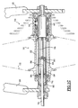
- FIG. 1A a hub 10 with spokes 12 has been shown. connected to a rim, not shown for clarity of the drawing, a cassette 14 to sprockets, a freewheel 16, a bicycle frame 18 and fixing means 20 fast.
- the hub includes a cylindrical part 22 of revolution with side wings 24 provided with holes 26 provided for receiving the ends of the rays.
- This hub further comprises a tube 28, inside left, in taking into account the direction of movement.
- a pair of bearings 30 ensures the free rotation of the cylindrical part 22 of revolution with respect to this tube 28, interior left.
- a seal 32 seals on the left side.
- This tube 28, inside left protrudes outside the part cylindrical of the hub to cooperate by a shoulder 34 with the frame 18, usually in a slot 36.
- the pinion cassette 14 comprises a cassette body 38 with grooves 40 in which internal teeth 41 slide pinions 42 to form a stack, spacing and thickness of each sprockets are well known and suitable for forming given stacks whose characteristics are well known.
- a nut 44 locks the stack on the body 38 of cassette.
- This cassette body 38 is mounted coaxially on a tube 46, inside right.
- This tube 46, right interior, has a shoulder 48 provided to cooperate with a slot 50, made in the frame 18, right side.
- a nut 52 secures the tube 46, right interior on the frame.
- a pair of bearings 54 with the corresponding locking circlips ensure the free rotation of the cassette body 38 relative to the tube 46, inside right.
- the freewheel 16 comprises for example in known manner a crown 56 internal with inclined notches, integral in rotation with the body 38 of cassette and free in translation thanks to grooves 58.
- a spring 60 of reminder tends to push this crown 56 against a ring 62 whose face in vis-à-vis also includes notches provided to cooperate with those of the crown, in the direction of training.
- the inclined notches of the crown 56 escape on the notches of the ring 62, ensuring disengagement.
- the ring 62 is also mounted free to rotate relative to the tube 46, right interior, thanks to a bearing 64.
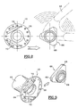
- the ring 62 further comprises on its outer periphery a adapter 66, leading, machined with said ring.
- This adapter is better represented and more visible in Figures 2 and 3.
- This adapter 66 has a triangular profile with truncated vertices 68, preferably registered in a circle.
- This triangle are designed to cooperate with a Receiving V 70 carried by the cylindrical body 22 of the hub.
- the two inner tubes 28 left and 46 right have a length adapted so that they abut when the device is mounted as shown in Figure 1A.
- connecting means 72 comprise a connecting tube 74 which comes be housed in a soft sliding fashion, coaxially, inside the two tubes 28 and 46 as well as a central operating axis 75.
- the connecting tube 74 comprises a first and a second lumen closed 76 and 78 respectively, each provided with a recess of blocking 80 and 82.
- the length of the first light is y while the length of the second light is x .
- the second light 78 receives a guide pin 84, in this case a screw 86, integral with the tube 28, inside left in which the tube 74 bond is likely to slide.
- the operating axis 75 has a length such that it projects from either side and on the other side of frame 18, outside.
- This operating axis is equipped on the left side with means 20 for quick clamping of known type, lever and eccentric and right side of a groove 86 provided to receive a clip 88.
- This operating axis 75 further comprises a pin 90 transverse arranged at a distance from the end.
- This operating axis is such that, once the device according to the invention in place, its straight end is located at a distance y from the end of the connecting tube 74.
- the length of the connecting tube 74 is such that the length of overlap with the straight tube is x .
- the length of this connecting tube is defined on the left so that there remains a free distance x between this connecting tube and the end of the left tube.
- the body 38 of the pinion cassette 42 is fixed to the frame 18 at nut 52.
- the ring 62 of the freewheel 16 is free to rotate as well as the adapter 66 which it carries, thanks to the bearing 64, which allows it to be oriented in any angular position.
- the quick fastening means 20 are open and the pin 75 is removed on the left with respect to the cylindrical hub body 22 and therefore with respect to the tube 28, interior left.
- the connecting tube 74 is in perfect superposition with tube 28, inside left, without protruding beyond the end right of the cylindrical hub body 22. Alone is protruding, by construction, the guide 70.
- the user approaches the rear wheel and follows the V 70 guide on adapter 66 by matching this Vé with one of the vertices 68 of this adapter. This maneuver is facilitated by the fact that the vertices are truncated so that the adapter self-orientates as soon as the wheel is inserted.
- the user translates the axle 75 by maneuvering quick fixing means. To do this, he first slightly rotate the axis so as to release the recess 82 from the light 78 of the connecting tube 74 outside the pin 84. Indeed, the tube 28, interior left is immobilized in rotation in the slot 36, easily by realization of a flat. Then just push it lightly, if necessary is since a first spring 92 is provided, interposed between the end left of the tube 28, inside left and a washer 94, blocked by a retaining rings 95.
- the connecting tube 74 moves and penetrates by a length x into the tube 46, right interior.
- the user in the same movement still slightly turns the fixing means 20 to release the pin 90 secured to the axis 75 of the recess 80 of the light 76.
- a second spring 96 of lower stiffness than the first, interposed between the washer 94 and the pin 90 ensures this displacement in addition to the thrust of the user to subject the axis 75 to a translation y , so that the end of this axis projects beyond the end of the tube 46, right interior, it then suffices to clip or pin this axis to ensure the locking in translation of the axis 75.
- the tightening of the eccentric of the quick fixing means 20 ensures the immobilization of the device according to the invention.
- the wheel is assembled.
- Disassembly is carried out by carrying out the different stages in order opposite to the one just described.
- the connecting tube comprises a first and a second circlip 400 and 402, arranged to release a stroke y between the two.
- a nut 404 and a lock nut 406 are screwed onto the axis 75, the end of which is threaded for this purpose.
- the nut 404 with the rod can slide freely between the two circlips, on the defined stroke.
- the right end of the tube 46, inside right, is threaded to receive by screwing the end of axis 75.
- the user maintains the operating means separated to the left to maintain the nut 404 against the first circlip 400 and thus avoid the protrusion of the connecting tube 74 relative to the tube 28, inside on the left during the 'introduction.
- the user then translates the axis 75 in a single movement which places the nut against the second circlip 402, after a displacement over a length y , then translates the connecting tube over a length x , at the same time as the axis 75 is screwed into the end of the tube 46, inside right.
- FIG. 5A a so-called pin variant is shown.
- the identical elements have the same references.
- the tube 46 inside right, includes a pin 500, transverse, in the immediate vicinity of the right end of this tube.
- the connecting tube 74 is fixed by its left end, at the end of the axis 75 by a nut 502 screwing on said axis and inside the tube of link.
- the assembly is adjusted and then immobilized by a lock nut 504.
- the right end of the connecting tube 74 is cut to form a light 506 straight, following a generator, with a recess of blocking 508, see Figure 5B.
- the straight light 506 is provided to cooperate with the spindle 500.
- axis 75 includes, upstream of the fixing by nut with the connecting tube 74 a groove 510 provided for receiving friction notched an elastic ring 512, integral with the end of the tube 28 interior left and projecting from the interior wall.
- the axis 75 is maintained in position translated to the left by the elastic ring 512 which penetrates in throat 510.
- the adapter 66 is an insert screwed into the body 38 cassette which is simplified due to the removal of the freewheel.
- This Vé has always the triangular profile with truncated points 68.
- the Vé 70 of guide it is made from the ring 62 of the freewheel.
- connection of axis 75 with the connecting tube 74 is modified in that the end of the axis 75 includes a head 602, for example of hexagonal shape, which is placed in a housing 604 in which it is kept blocked by a circlip 606.
- the axis 75 has a certain angular freedom relative to the tube 74 linkage, thus ensuring self-alignment.
- the connecting tube 74 is identical to that shown in FIG. 5B in sort of making the 506 straight light and the 508 offset cooperate with pin 600.
- An assistance spring 612 interposed between the end of the tube 28, inside left and the head 602 secured to the axis 75 makes it possible to recall the connecting tube which is integral to the right to ensure the safety of link.
- a lock nut 614 disposed in the means 20 quick fixing, combined with a 75 axis thread allows adjustment of the available axis length 75 and precise fitting adjustment.
- the entire wheel and the cassette can be disassembled together when the nut 52 is previously loosened.
- the wheel, hub and pinion assembly in the first position, if this nut is loose, the wheel, hub and pinion assembly can be removed at condition to keep the cassette pressed against the hub because immediately after disassembly nothing keeps the two parts against each other.
- the framework which comprises generally a slot for positioning the hub axle can be modified to understand only one leg with a hole with a flat anti-rotation in which the pinion cassette is screwed, which is another advantage. This also allows a strengthening of this part of the frame which also carries the derailleur.
Description
La présente invention concerne un dispositif de montage de la roue, notamment arrière d'un deux-roues en sorte de permettre le démontage en laissant la chaíne en place sur son pignon d'arbre.The present invention relates to a device for mounting the wheel, in particular rear of a two-wheeler so as to allow disassembly in leaving the chain in place on its sprocket.
Le terme deux-roues est utilisé à bon escient car la présente invention est décrite en application à un vélo par souci de simplification mais se trouve applicable par transposition directe à une moto, au nombre de pignons près puisque la moto ne comporte qu'une seule couronne à l'arrière au lieu d'une cassette de pignons.The term two-wheeler is used wisely because the present invention is described in application to a bicycle for the sake of simplification but is found applicable by direct transposition to a motorcycle, to the number of pinions since the bike has only one crown on the back instead of one sprocket cassette.
On sait en effet que le démontage de la roue arrière d'un vélo pose des problèmes car les pignons sont solidaires du moyeu de la roue.We know that removing the rear wheel from a bicycle poses problems because the pinions are integral with the wheel hub.
En effet, la roue arrière d'un vélo comprend un moyeu sur les bords duquel sont fixés les rayons qui supportent la jante. Ce moyeu comprend de façon connue un arbre intérieur avec des roulements interposés, les deux extrémités de cet arbre venant se fixer sur les extrémités du cadre du vélo, dans des logements prévus à cet effet.Indeed, the rear wheel of a bicycle includes a hub on the edges from which are fixed the spokes which support the rim. This hub includes known manner an inner shaft with interposed bearings, both ends of this tree coming to be fixed on the ends of the frame of the bicycle, in housing provided for this purpose.
L'arbre est maintenu en place généralement par des moyens de fixation rapide, à excentrique.The shaft is generally held in place by fastening means fast, eccentric.
Le dérailleur est également fixé sur le cadre, au niveau de cet arbre, en sorte de rester sur le cadre lorsque la roue est démontée.The derailleur is also attached to the frame, at this shaft, in kind of stay on the frame when the wheel is removed.
La chaíne est disposée entre un plateau ou un jeu de plateaux et une cassette de pignons, cette cassette étant solidaire en rotation du moyeu avec des moyens de mise en roue libre de cette cassette de pignons par rapport audit moyeu.The chain is arranged between a tray or a set of trays and a sprocket cassette, this cassette being integral in rotation with the hub with means for freewheeling this pinion cassette relative to said hub.
Lorsque la roue doit être démontée pour quelque raison que ce soit, crevaison, rangement dans un coffre de voiture ou entretien, l'utilisateur est amené à desserrer les moyens de fixation rapide de l'arbre de roue puis à dégager la roue du cadre tout en soulevant la chaíne en sorte de dégager la cassette de pignons.When the wheel has to be removed for any reason, puncture, storage in a car trunk or maintenance, the user is led to loosen the quick-release means of the wheel shaft and then to release the wheel from the frame while lifting the chain so as to release the sprocket cassette.
La manoeuvre est plutôt insatisfaisante pour plusieurs raisons.The maneuver is rather unsatisfactory for several reasons.
Tout d'abord, si le changement doit être rapide, on note que le dégagement des pignons fait perdre un temps précieux. De plus, le temps perdu est encore plus important pour la remise en place d'une roue de secours.First, if the change is to be rapid, we note that the releasing the pinions wastes precious time. In addition, the time lost is even more important when replacing a spare tire.
Cette perte de temps est tellement sensible que dans les courses, les coureurs ont pour consigne de ramener la chaíne sur le petit pignon dès la crevaison par exemple, en sorte que les mécaniciens puissent acquérir des gestes systématiques et que la manoeuvre soit facilitée par la position de la chaíne sur le plus petit pignon donc celui qui est extérieur. On comprend immédiatement le problème, le coureur est obligé de redémarrer sur un grand développement, ce qui explique les poussées du coureur par le mécanicien nécessaires pour une relance.This loss of time is so noticeable that in races, runners are instructed to bring the chain back to the sprocket as soon as puncture for example, so that mechanics can acquire systematic gestures and that the maneuver is facilitated by the position of the chain on the smallest sprocket so the one that is outside. We understand the problem immediately, the runner is forced to restart on a large development, which explains the thrusts of the runner by the mechanic needed for a raise.
Dans le cas d'un démontage pour un rangement dans un coffre ou pour un entretien, la vitesse n'est plus déterminante mais on note alors que dès que la roue est retirée, la chaíne est détendue et pend entre les plateaux et le dérailleur, ce qui occasionne des désagréments, salissures du coffre ou chaíne traínant dans la terre entre autres. La chaíne peut aussi se vriller ou s'emmêler.In the case of disassembly for storage in a trunk or for an interview, speed is no longer decisive but we note that as soon as the wheel is removed, the chain is relaxed and hangs between the chainrings and the derailleur, which causes inconvenience, soiling of the boot or chain trailing in the earth among others. The chain can also twist or become tangled.
On remarque aussi que tout changement de roue entraíne le retrait de la cassette de pignons si bien que toutes les roues doivent être équipées d'un jeu de pignons. Outre l'aspect financier, il faut savoir que tous les coureurs n'utilisent pas les mêmes pignons si bien qu'il faut des roues différentes équipées de cassettes de pignons propres à chaque coureur, multipliant le nombre de roues à gérer.We also note that any change of wheel causes the withdrawal of the sprocket cassette so that all wheels must have a clearance gables. Besides the financial aspect, you should know that all runners do not use the same sprockets so different wheels are required fitted with pinion cassettes specific to each runner, multiplying the number of wheels to manage.
On sait aussi que les réglages des dérailleurs sont de plus en plus délicats et le démontage de roues peut perturber ces réglages. We also know that the settings of the derailleurs are more and more delicate and removing the wheels can disturb these adjustments.
On sait aussi que dans le cas de certains agencements, notamment dans le cas des dérailleurs de type à chape inversée, le démontage est encore plus délicat. We also know that in the case of certain arrangements, in particular in the case of reverse clevis type derailleurs, disassembly is still more delicate.
La demande de brevet européen EP 0 896 887 A1 montre un assemblage d'un moyeu conventionnel incluant un corps de cassette pour le montage de pignons d'entraínement, le corps de cassette étant fixé de manière dégageable au moyeu cylindrique. Un premier tube est monté libre en rotation autour de l'axe à l'intérieur du moyeu. Un second tube est monté en rotation dans le premier tube et aussi à l'intérieur du corps de cassette. La référence ne montre pas un tube de liaison prévu pour coulisser dans les premier et second tubes.European patent application EP 0 896 887 A1 shows an assembly of a conventional hub including a cassette body for mounting drive sprockets, the cassette body being releasably attached to the cylindrical hub. A first tube is mounted free to rotate about the axis at inside the hub. A second tube is rotatably mounted in the first tube and also inside the cassette body. The reference does not show a tube of link provided to slide in the first and second tubes.
La demande de brevet international WO 97/02149 montre un dispositif d'entraínement d'une roue libre pour un vélo incluant un premier tube monté en rotation à l'intérieur du moyeu cylindrique. Un second tube est fourni qui est en rotation à l'intérieur du corps de cassette pour les pignons d'entraínement. Ces deux tube sont interreliés dans les conditions assemblées aux moyens d'une tige étendue à travers les tubes. Le corps de cassette et le moyeu cylindrique sont liés l'un à l'autre de manière dégageable.International patent application WO 97/02149 shows a device freewheel drive for a bicycle including a first tube mounted in rotation inside the cylindrical hub. A second tube is provided which is in rotation inside the cassette body for the drive sprockets. These two tubes are interconnected under the conditions assembled by means of a rod extended through the tubes. Cassette body and cylindrical hub are linked to each other in a releasable manner.
La présente invention propose un dispositif de montage d'un moyeu de roue arrière qui permet le démontage de la roue tout en laissant en place la cassette de pignons, qui conserve la résistance des agencements de l'art antérieur, qui évite l'augmentation du nombre de pièces, qui est directement adaptable aux roues arrières des deux-roues existants, qui est d'une fiabilité certaine et qui évite tout retrait intempestif de la roue même en cas de remontage incomplet du dispositif.The present invention provides a device for mounting a hub of rear wheel which allows the disassembly of the wheel while leaving the sprocket cassette, which retains the resistance of art fixtures anterior, which avoids the increase in the number of parts, which is directly adaptable to the rear wheels of existing two-wheelers, which is of a certain reliability and which prevents any unwanted removal of the wheel even in the event of incomplete reassembly of the device.
Selon la présente invention, un dispositif de montage d'un moyeu de roue est équipé tel que défini en revendication 1. Les modes de réalisation du dispositif de montage sont définis en revendications 2 à 9. Le présent dispositif de montage inclut un premier tube monté libre en rotation à l'intérieur du moyeu et est muni de moyens de fixation sur le cadre. Un second tube est monté libre en rotation à l'intérieur du corps de cassette et est muni de moyens de fixation sur le cadre et des moyens de liaison sont fournis pour interrelier ces deux tubes. Des moyens de manoeuvre de ces moyens de liaison incluent des moyens de blocage des moyens de manoeuvre. De plus, des moyens de liaison amovibles sont fournis pour interrelier le corps de cassette et le moyeu cylindrique.According to the present invention, a device for mounting a wheel hub is equipped as defined in claim 1. The embodiments of the device The mounting devices are defined in claims 2 to 9. The present mounting device includes a first tube mounted free to rotate inside the hub and is provided with fixing means on the frame. A second tube is mounted free to rotate at inside the cassette body and is provided with fixing means on the frame and connecting means are provided to interconnect these two tubes. Means of operation of these connecting means include means for blocking means maneuver. In addition, removable connecting means are provided for interconnect the cassette body and the cylindrical hub.
Les moyens de liaison incluent un tube de liaison prévu pour coulisser dans le premier et le second tubes entre au moins une première position dans laquelle le tube de liaison est rétracté dans le premier tube et une seconde position dans laquelle le tube de liaison est en saillie hors du premier tube et pénètre dans le second tube lorsque les premier et second tubes sont alignés. The connecting means include a connecting tube intended to slide in the first and second tubes enter at least a first position in which the connecting tube is retracted into the first tube and a second position in which the connecting tube protrudes out of the first tube and enters the second tube when the first and second tubes are aligned.
Selon un premier mode de réalisation, le tube de liaison comprend une lumière fermée prévue pour recevoir une goupille solidaire des moyens de manoeuvre.According to a first embodiment, the connecting tube comprises a closed light provided to receive a pin secured to the means of maneuver.
Selon un premier mode de réalisation, le tube de liaison comprend au moins une lumière rectiligne débouchante avec un décrochement, prévue pour coopérer avec au moins une broche solidaire du second tube.According to a first embodiment, the connecting tube comprises at minus a rectilinear opening light with a recess, provided for cooperate with at least one pin integral with the second tube.
Plus particulièrement, les moyens de manoeuvre comprennent un axe de manoeuvre central, solidaire des moyens de blocage et mobile en translation et en rotation par rapport au premier tube.More particularly, the maneuvering means comprise an axis of central operation, integral with the locking means and movable in translation and in rotation relative to the first tube.
Les moyens amovibles de liaison en rotation du corps de cassette et du corps cylindrique de moyeu comprennent un Vé de guidage côté moyeu et un adaptateur côté cassette.The removable means for rotationally connecting the cassette body and the hub cylindrical body include a hub side guide Vee and a cassette side adapter.
L'adaptateur est de forme triangulaire.The adapter is triangular in shape.
Ce dispositif comprend en outre des moyens de rappel élastique des moyens de liaison en position de liaison et des moyens de retenue à frottement doux cranté des moyens de manoeuvre par rapport au premier tube.This device further comprises elastic return means of the connecting means in the connecting position and retaining means at soft notched friction of the operating means relative to the first tube.
La présente invention est maintenant décrite en regard des dessins annexés sur lesquels les différentes figures représentent :
- figures 1A, 1B et 1C, une vue en coupe médiane d'un moyeu de roue équipé du dispositif selon l'invention avec les différentes étapes,
- figure 2, une vue en coupe de l'adaptateur menant et du Vé de guidage mené du dispositif,
- figure 3, une vue en perspective de l'adaptateur et du Vé de guidage du dispositif,
- figure 4, une vue d'un premier mode de réalisation sensiblement identique à celui de la figure 1 mais avec un montage vissé,
- figure 5A, une vue d'un second mode de réalisation perfectionné, plus particulièrement adapté aux vélos dits routiers,
- figure 5B, une vue en perspective du tube de liaison type broche, et
- figure 6, une vue d'un troisième mode de réalisation, plus particulièrement adapté aux vélos dits tout terrain.
- FIGS. 1A, 1B and 1C, a view in median section of a wheel hub equipped with the device according to the invention with the different stages,
- FIG. 2, a sectional view of the driving adapter and of the driven guide V of the device,
- FIG. 3, a perspective view of the adapter and the guide V of the device,
- FIG. 4, a view of a first embodiment substantially identical to that of FIG. 1 but with a screwed assembly,
- FIG. 5A, a view of a second improved embodiment, more particularly suitable for so-called road bikes,
- FIG. 5B, a perspective view of the pin-type connecting tube, and
- Figure 6, a view of a third embodiment, more particularly suitable for so-called mountain bikes.
Sur la figure 1A, on a représenté un moyeu 10 avec des rayons 12
reliés à une jante, non représentée pour la clarté du dessin, une cassette 14 à
pignons, une roue libre 16, un cadre 18 de vélo et des moyens 20 de fixation
rapide.In FIG. 1A, a
Le moyeu comprend une partie 22 cylindrique de révolution avec des
ailes 24 latérales munies de trous 26 prévus pour recevoir les extrémités des
rayons.The hub includes a
Ce moyeu comprend en outre un tube 28, intérieur gauche, en
tenant compte du sens de déplacement. Une paire de roulements 30 assure la
libre rotation de la partie 22 cylindrique de révolution par rapport à ce
tube 28, intérieur gauche. Un joint 32 assure l'étanchéité côté gauche.This hub further comprises a
Ce tube 28, intérieur gauche dépasse à l'extérieur de la partie
cylindrique du moyeu pour coopérer par un épaulement 34 avec le cadre 18,
généralement dans une fente 36.This
La cassette 14 à pignons comprend un corps 38 de cassette avec des
cannelures 40 dans lesquelles viennent se glisser des dents 41 internes des
pignons 42 pour former un empilement, l'espacement et l'épaisseur de chacun
des pignons sont bien connus et adaptés pour former des empilements donnés
dont les caractéristiques sont bien connues.The
Un écrou 44 assure le blocage de l'empilement sur le corps 38 de
cassette.A
Ce corps 38 de cassette est monté coaxialement sur un tube 46,
intérieur droit. Ce tube 46, intérieur droit, comporte un épaulement 48
prévu pour coopérer avec une fente 50, ménagée dans le cadre 18, côté droit.This
Un écrou 52 assure le blocage du tube 46, intérieur droit sur le
cadre.A
Une paire de roulements 54 avec les circlips de blocage correspondants
assurent la libre rotation du corps 38 de cassette par rapport au tube 46,
intérieur droit. A pair of
La roue libre 16 comprend par exemple de façon connue une couronne
56 interne avec des crans inclinés, solidaire en rotation du corps 38 de
cassette et libre en translation grâce à des cannelures 58. Un ressort 60 de
rappel tend à pousser cette couronne 56 contre une bague 62 dont la face en
vis à vis comporte aussi des crans prévus pour coopérer avec ceux de la
couronne, dans le sens d'entraínement. Lorsque le corps 38 de pignons est
retenu par la chaíne, les crans inclinés de la couronne 56 échappent sur les
crans de la bague 62, assurant un débrayage.The
La bague 62 est également montée libre en rotation par rapport au
tube 46, intérieur droit, grâce à un roulement 64.The
La bague 62 comprend en outre sur sa périphérie extérieure un
adaptateur 66, menant, venu d'usinage avec ladite bague. Cet adaptateur est
mieux représenté et plus visible sur les figures 2 et 3.The
Cet adaptateur 66 a un profil triangulaire à sommets 68 tronqués,
inscrits préférentiellement dans un cercle.This
Les dimensions de ce triangle sont prévues pour venir coopérer avec un
Vé 70 de réception porté par le corps 22 cylindrique du moyeu.The dimensions of this triangle are designed to cooperate with a
Les deux tubes intérieur gauche 28 et droit 46 ont une longueur
adaptée pour qu'ils viennent en aboutement lorsque le dispositif est monté
ainsi que montré sur la figure 1A.The two
L'ensemble du dispositif qui vient d'être décrit est complété par des
moyens 72 de liaison des deux tubes.The entire device which has just been described is supplemented by
Ces moyens 72 de liaison comprennent un tube 74 de liaison qui vient
se loger à coulissement doux, de façon coaxiale, à l'intérieur des deux
tubes 28 et 46 ainsi qu'un axe 75 de manoeuvre, central.These connecting means 72 comprise a connecting
Le tube 74 de liaison comprend une première et une seconde lumières
fermées 76 et 78 respectivement, munies chacune d'un décrochement de
blocage 80 et 82.The connecting
La longueur de la première lumière est de y tandis que la longueur de la seconde lumière est de x. The length of the first light is y while the length of the second light is x .
La seconde lumière 78 reçoit un pion 84 de guidage, en l'occurrence
une vis 86, solidaire du tube 28, intérieur gauche dans lequel le tube 74
de liaison est susceptible de coulisser.The
L'axe 75 de manoeuvre a une longueur telle qu'il fait saillie de part et
d'autre du cadre 18, à l'extérieur.The operating
Cet axe de manoeuvre est équipé côté gauche des moyens 20 de
serrage rapide de type connu, à levier et excentrique et côté droit d'une gorge
86 prévue pour recevoir un clip 88.This operating axis is equipped on the left side with means 20 for
quick clamping of known type, lever and eccentric and right side of a
Cet axe 75 de manoeuvre comprend en outre une goupille 90
transversale disposée à une distance de l'extrémité.This operating
La longueur de cet axe de manoeuvre est telle que, une fois le dispositif
selon l'invention en place, son extrémité droite se trouve à une distance y de
l'extrémité du tube 74 de liaison.The length of this operating axis is such that, once the device according to the invention in place, its straight end is located at a distance y from the end of the connecting
De plus, la longueur du tube 74 de liaison est telle que la longueur de
recouvrement avec le tube droit est de x. La longueur de ce tube de
liaison est définie à gauche en sorte qu'il reste une distance x libre entre ce
tube de liaison et l'extrémité du tube gauche.In addition, the length of the connecting
Les montage et démontage du dispositif qui vient d'être décrit sont maintenant indiqués en regard des différentes figures 1A, 1B, 1C, 2 et 3.The assembly and disassembly of the device which has just been described are now indicated with reference to the different figures 1A, 1B, 1C, 2 and 3.
Le corps 38 de la cassette de pignons 42 est fixé sur le cadre 18 au
moyen de l'écrou 52.The
La bague 62 de la roue libre 16 est libre en rotation ainsi que
l'adaptateur 66 qu'elle porte, grâce au roulement 64, ce qui lui permet d'être
orientée dans n'importe quelle position angulaire.The
L'utilisateur tient en main la roue arrière équipé du moyeu 10. Les
moyens de fixation rapide 20 sont ouverts et l'axe 75 est retiré sur la gauche
par rapport au corps 22 cylindrique de moyeu et donc par rapport au
tube 28, intérieur gauche. Le tube 74 de liaison est en superposition parfaite
avec le tube 28, intérieur gauche, sans faire saillie au delà de l'extrémité
droite du corps 22 cylindrique de moyeu. Seul est en saillie, par construction,
le Vé 70 de guidage. The user holds in his hand the rear wheel fitted with the
L'utilisateur approche la roue arrière et emboíte le Vé 70 de guidage sur
l'adaptateur 66 en faisant correspondre ce Vé avec l'un des sommets 68 de
cet adaptateur. Cette manoeuvre est facilitée par le fait que les sommets sont
tronqués si bien que l'adaptateur s'auto-oriente dès l'introduction de la roue.The user approaches the rear wheel and follows the
Dès que la roue est emboítée à fond de Vé, l'utilisateur translate l'axe
75 par manoeuvre des moyens de fixation rapide. Pour cela, il fait d'abord
tourner légèrement l'axe en sorte de dégager le décrochement 82 de la lumière
78 du tube de liaison 74 hors du pion 84. En effet, le tube 28, intérieur
gauche est immobilisé en rotation dans la fente 36, de façon aisée par
réalisation d'un méplat. Il lui suffit ensuite de pousser légèrement, si besoin
est puisqu'il est prévu un premier ressort 92, interposé entre l'extrémité
gauche du tube 28, intérieur gauche et une rondelle 94, bloquée par un
circlips 95.As soon as the wheel is fitted to the bottom of the V, the user translates the
Le tube de liaison 74 se déplace et pénètre d'une longueur x dans le
tube 46, intérieur droit.The connecting
L'utilisateur, dans le même mouvement tourne encore légèrement les
moyens de fixation 20 pour dégager la goupille 90 solidaire de l'axe 75 du
décrochement 80 de la lumière 76. Un second ressort 96, de plus faible
raideur que le premier, interposé entre la rondelle 94 et la goupille 90 assure
ce déplacement en complément de la poussée de l'utilisateur pour faire subir à
l'axe 75 une translation y, si bien que l'extrémité de cet axe fait saillie au-delà
de l'extrémité du tube 46, intérieur droit, il suffit alors de clipser ou
brocher cet axe pour assurer le blocage en translation de l'axe 75. Le serrage
de l'excentrique des moyens 20 de fixation rapide assure l'immobilisation du
dispositif selon l'invention.The user, in the same movement still slightly turns the fixing means 20 to release the
Le montage de la roue est assuré.The wheel is assembled.
Le démontage s'effectue en réalisant les différentes étapes dans l'ordre inverse de celui qui vient d'être décrit.Disassembly is carried out by carrying out the different stages in order opposite to the one just described.
On note que dans tous les cas, dès que la première translation est
effectuée et que le tube 74 de liaison pénètre dans le tube 46, intérieur
droit, la liaison axiale est réalisée et le dispositif peut fonctionner, c'est à dire
que l'utilisateur peut monter sur son vélo sans danger. We note that in all cases, as soon as the first translation is
performed and the connecting
Par contre, la coopération entre le Vé 70 et l'adaptateur risque d'être de
piètre qualité avec des désemboítements répétés mais cela sans danger pour
l'utilisateur, d'où la nécessité de verrouiller l'axe 75.On the other hand, cooperation between the
Sur la figure 4, on retrouve les éléments essentiels du mode de réalisation précédent qui porte les mêmes références, mais avec une simplification du montage.In Figure 4, we find the essential elements of the previous achievement which has the same references, but with a simplification of assembly.
En effet, le tube 28, intérieur gauche, est exempt de pion tout
comme le tube de liaison qui est exempt de lumières. Le tube de liaison
comprend un premier et un second circlips 400 et 402, disposés pour libérer
une course y entre les deux. Un écrou 404 et un contre-écrou 406 sont vissés
sur l'axe 75 dont l'extrémité est filetée a cet effet.Indeed, the
L'écrou 404 avec la tige peuvent coulisser librement entre les deux
circlips, sur la course définie.The
L'extrémité droite du tube 46, intérieur droit, est filetée pour
recevoir par vissage l'extrémité de l'axe 75.The right end of the
Dans cette variante, l'utilisateur maintient les moyens de manoeuvre
écartés vers la gauche pour maintenir l'écrou 404 contre le premier circlip 400
et éviter ainsi la mise en saillie du tube de liaison 74 par rapport au tube
28, intérieur gauche lors de l'introduction. L'utilisateur translate alors en un
seul mouvement l'axe 75 ce qui plaque l'écrou contre le second circlip 402,
après un déplacement sur une longueur y, puis translate le tube de liaison sur
une longueur x , en même temps que l'axe 75 est vissé dans l'extrémité du
tube 46, intérieur droit.In this variant, the user maintains the operating means separated to the left to maintain the
Cette variante est particulièrement économique par le faible nombre de pièces qu'elle met en jeu. On peut aussi, pour la rendre encore plus économique, remplacer les moyens de fixation rapide 20 du type à levier et excentrique par de simples vis à papillon.This variant is particularly economical by the low number of pieces it brings into play. We can also, to make it even more economical, replace the quick-fixing means 20 of the lever type and eccentric by simple butterfly screws.
Sur la figure 5A, une variante dite à broche est représentée. Les éléments identiques portent les mêmes références.In FIG. 5A, a so-called pin variant is shown. The identical elements have the same references.
Le tube 46, intérieur droit, comprend une broche 500,
transversale, à proximité immédiate de l'extrémité droite de ce tube. The
Le tube 74 de liaison est fixé par son extrémité gauche, à l'extrémité de
l'axe 75 par un écrou 502 vissant sur ledit axe et à l'intérieur du tube de
liaison. L'ensemble est ajusté puis immobilisé par un contre-écrou 504.The connecting
L'extrémité droite du tube 74 de liaison est découpée pour former une
lumière 506 rectiligne, suivant une génératrice, avec un décrochement de
blocage 508, voir figure 5B.The right end of the connecting
La lumière 506 rectiligne est prévue pour coopérer avec la broche 500.The
En complément, l'axe 75 comprend, en amont de la fixation par écrou
avec le tube 74 de liaison une gorge 510 prévue pour recevoir à frottement
cranté un anneau 512 élastique, solidaire de l'extrémité du tube 28
intérieur gauche et en saillie sur la paroi intérieure.In addition,
Dans ce mode de réalisation, lors du remontage, l'axe 75 est maintenu
en position translatée vers la gauche par l'anneau 512 élastique qui pénètre
dans la gorge 510.In this embodiment, during reassembly, the
Lorsque l'utilisateur a emboíté la roue par coopération du Vé 70 de
guidage avec l'adaptateur 66, il débloque l'axe 75 par simple pression et
pousse ledit axe vers la droite jusqu'à ce que l'extrémité du tube 74 de liaison
vienne en butée sur la broche 500. Par une légère rotation, si nécessaire, il
dispose la lumière rectiligne en face de ladite broche pour que celle-ci pénètre
dans cette lumière et par rotation, la broche 500 est bloquée dans le
décrochement 508.When the user has fitted the wheel by cooperation of the
Il suffit ensuite de serrer les moyens 20 de fixation rapide pour assurer l'immobilisation du dispositif.Then simply tighten the quick fastening means 20 to ensure immobilization of the device.
Sur la figure 6, on a représenté une variante plus particulièrement applicable au vélo tout terrain dit VTT.In Figure 6, there is shown a more particularly variant applicable to mountain biking called mountain biking.
On note que la roue libre est rapportée dans le corps 22 cylindrique de
moyeu.We note that the freewheel is attached to the
De plus, l'adaptateur 66 est une pièce rapportée vissée dans le corps 38
de cassette qui est simplifié du fait du retrait de la roue libre. Ce Vé a toujours
le profil triangulaire à pointes 68 tronquées. Quant au Vé 70 de guidage, il est
réalisé à partir de la bague 62 de la roue libre. In addition, the
Dans cette variante, également à broche, la liaison de l'axe 75 avec le
tube 74 de liaison est modifiée en ce sens que l'extrémité de l'axe 75
comprend une tête 602, par exemple de forme hexagonale, qui vient se placer
dans un logement 604 dans lequel elle est maintenue bloquée par un circlip
606. Ainsi l'axe 75 dispose d'une certaine liberté angulaire par rapport au tube
74 de liaison, assurant ainsi un auto-alignement.In this variant, also with spindle, the connection of
Un agencement identique avec une gorge 608 et un anneau 610
élastique permet un frottement cranté entre l'axe 75 et le tube 28, en
position dégagée.Identical arrangement with a
Le tube 74 de liaison est identique à celui représenté sur la figure 5B en
sorte de faire coopérer la lumière 506 rectiligne et le décrochement 508 avec
la broche 600.The connecting
On peut aussi prévoir un méplat sur le tube 46, à son extrémité
droite pour permettre un positionnement angulaire précis de la broche 600, ce
qui facilite la mise en place de l'axe 75 et des moyens 20 de fixation rapide
toujours dans la même position.One can also provide a flat on the
Un ressort d'assistance 612, interposé entre l'extrémité du tube
28, intérieur gauche et la tête 602 solidaire de l'axe 75 permet de rappeler le
tube de liaison qui en est solidaire vers la droite pour assurer la sécurité de
liaison.An
Dans cette variante, un contre-écrou 614, disposé dans les moyens 20
de fixation rapide, combiné avec un filetage de l'axe 75 permet le réglage de la
longueur disponible de l'axe 75 et un ajustement précis du montage.In this variant, a
On note que dans tous les cas, l'ensemble de la roue et de la cassette
peut être démonté ensemble lorsque l'écrou 52 est préalablement desserré.
Dans le cas du premier mode de réalisation, dans la première position, si cet
écrou est desserré, l'ensemble roue, moyeu et pignon peut être retiré à
condition de maintenir la cassette pressée contre le moyeu car dès après le
démontage plus rien ne retient les deux parties l'une contre l'autre.Note that in all cases, the entire wheel and the cassette
can be disassembled together when the
Par contre, dans le cas par exemple de la variante de la figure 1A, si le
clip 88 est laissé en place, le problème de liaison est résolu, surtout que le
déverrouillage des moyens 20 de fixation rapide permet le desserrage aisé de
l'écrou 52.On the other hand, in the case for example of the variant of FIG. 1A, if the
On note aussi que dans le cas de l'invention, le cadre qui comprend généralement une fente de mise en place de l'axe du moyeu peut être modifié pour ne comprendre qu'une patte avec un trou avec un méplat d'antirotation dans lequel est vissée la cassette de pignons, ce qui est un autre avantage. Ceci permet aussi un renforcement de cette partie du cadre qui porte aussi le dérailleur.It is also noted that in the case of the invention, the framework which comprises generally a slot for positioning the hub axle can be modified to understand only one leg with a hole with a flat anti-rotation in which the pinion cassette is screwed, which is another advantage. This also allows a strengthening of this part of the frame which also carries the derailleur.
Il est aussi à remarquer que l'adaptateur 66 est représenté menant et le
Vé 70 est mené mais un agencement inversé pourrait tout aussi bien être mis
en oeuvre sans sortir du cadre du dispositif selon la présente invention.It should also be noted that the
Claims (9)
- Wheel hub fitting device, in particular for a rear wheel of two-wheelers, on a frame, in particular for a bicycle, comprising at least one driving sprocket (42) of the rear wheel mounted on a cassette body (38) and a hub (10) with a cylindrical body (22) provided with lateral flanges (24) adapted to receive spokes (12) comprising:characterized in that the connection means (72) comprise a connection tube (74) designed to slide in the first and second tube between at least a first position in which the connection tube is retracted inside the first tube and a second position in which the connection tube is projecting outside the first tube and enters the second tube when the first and second tube are aligned.a first tube (28) mounted freely rotatable inside the hub and provided with fixing means on the frame,a second tube (46) mounted freely rotatable inside the cassette body (38) and provided with fixing means (52) of the frame,connection means (72) of these two tubes,maneuver means (75) of these connection means with locking means (20) of these maneuver means, and removable connection means (66, 70) rotatable with respect to the cassette body and to the cylindrical body of the hub
- Device according to claim 1, wherein it comprises a free wheel mechanism (16) interposed between the first tube (28) and the cylindrical body (22) of the hub or between the second tube (46) and the cassette body (38).
- Fitting device according to claim 1 or 2, wherein the connection tube (74) comprises a closed slot (76) designed to receive a pin (90) fixedly connected with the maneuver means (75).
- Fitting device according to claim 1 or 2, wherein the connection tube (74) comprises at least one rectilinear opening (506) with a side portion (508), provided to cooperate with at least one pin (500, 600) fixedly connected to the second tube (46).
- Fitting device according to any one of the preceding claims, wherein the maneuver means comprise a central maneuver shaft (75) fixedly connected with the locking means and translationally movable and rotatable relative to the first tube (28).
- Fitting device according to any one of the preceding claims, wherein the removable connection means rotatable with respect to the cassette body and the cylindrical body comprise a guide portion (70) on the side of the hub and an adapter (66) on the side of the cassette or conversely.
- Fitting device according to claim 6, wherein the adapter (66) is triangular.
- Fitting device according to any one of the preceding claims, wherein the connection means further comprise resilient return means (92, 96).
- Fitting device according to any one of the preceding claims, further comprising retention means with a notched frictional fit of the maneuver means with respect to the first tube (28).
Priority Applications (6)
| Application Number | Priority Date | Filing Date | Title |
|---|---|---|---|
| DE1997631523 DE69731523T2 (en) | 1997-07-11 | 1997-07-11 | Two-wheel hub assembly device |
| EP19970450018 EP0890505B1 (en) | 1997-07-11 | 1997-07-11 | Wheel hub mounting assembly for a two wheeler |
| AT98937607T ATE225275T1 (en) | 1997-07-11 | 1998-07-10 | HUB MOUNTING DEVICE FOR TWO-WHEEL |
| PCT/FR1998/001499 WO1999002392A1 (en) | 1997-07-11 | 1998-07-10 | Improved mounting device for a wheel hub of a two-wheeled vehicle |
| EP98937607A EP0993402B1 (en) | 1997-07-11 | 1998-07-10 | Improved mounting device for a wheel hub of a two-wheeled vehicle |
| DE69808470T DE69808470T2 (en) | 1997-07-11 | 1998-07-10 | HUB MOUNTING DEVICE FOR TWO-WHEEL |
Applications Claiming Priority (1)
| Application Number | Priority Date | Filing Date | Title |
|---|---|---|---|
| EP19970450018 EP0890505B1 (en) | 1997-07-11 | 1997-07-11 | Wheel hub mounting assembly for a two wheeler |
Publications (2)
| Publication Number | Publication Date |
|---|---|
| EP0890505A1 EP0890505A1 (en) | 1999-01-13 |
| EP0890505B1 true EP0890505B1 (en) | 2004-11-10 |
Family
ID=8230008
Family Applications (1)
| Application Number | Title | Priority Date | Filing Date |
|---|---|---|---|
| EP19970450018 Expired - Lifetime EP0890505B1 (en) | 1997-07-11 | 1997-07-11 | Wheel hub mounting assembly for a two wheeler |
Country Status (2)
| Country | Link |
|---|---|
| EP (1) | EP0890505B1 (en) |
| DE (1) | DE69731523T2 (en) |
Cited By (4)
| Publication number | Priority date | Publication date | Assignee | Title |
|---|---|---|---|---|
| US7530645B2 (en) | 2007-03-01 | 2009-05-12 | Shimano Inc. | Bicycle wheel securing structure |
| US7537291B2 (en) | 2007-02-01 | 2009-05-26 | Shimano Inc. | Bicycle wheel securing structure |
| US7556321B2 (en) | 2007-02-01 | 2009-07-07 | Shimano Inc. | Bicycle wheel securing structure |
| US7648211B2 (en) | 2007-06-19 | 2010-01-19 | Shimano Inc. | Bicycle wheel securing structure |
Families Citing this family (22)
| Publication number | Priority date | Publication date | Assignee | Title |
|---|---|---|---|---|
| FR2776612B1 (en) | 1998-03-30 | 2002-01-25 | Franck Savard | IMPROVEMENT IN THE DEVICE FOR MOUNTING A WHEEL HUB OF TWO WHEELS |
| US6290304B1 (en) * | 2000-05-03 | 2001-09-18 | Charles Mark Lashinske | Quick connect/release wheel and hub assembly |
| US6409281B1 (en) | 2000-12-04 | 2002-06-25 | Shimano Inc. | Bicycle hub with spacer and detachable freewheel |
| US6435622B1 (en) | 2000-12-06 | 2002-08-20 | Shimano Inc. | Bicycle hub with threaded spacer and detachable freewheel |
| US6497314B2 (en) | 2000-12-07 | 2002-12-24 | Shimano Inc. | Bicycle hub with sliding engagement member and detachable freewheel |
| US6523659B2 (en) | 2000-12-11 | 2003-02-25 | Shimano Inc. | Bicycle hub with tight connection ratchet and detachable freewheel |
| JP3696189B2 (en) * | 2002-08-26 | 2005-09-14 | 株式会社シマノ | Bicycle hub dynamo |
| FR2855099B1 (en) | 2003-05-23 | 2006-07-07 | Mavic Sa | CENTRIAL HUB OF A BICYCLE WHEEL AND WHEEL EQUIPPED WITH SUCH HUB |
| GB2414971B (en) | 2004-06-09 | 2006-12-27 | Simon Charles Bartlett | Improvements to wheel clamping assemblies |
| US7628416B2 (en) | 2007-02-21 | 2009-12-08 | Shimano Inc. | Bicycle wheel securing structure |
| DE102008029136A1 (en) * | 2008-06-19 | 2009-12-24 | Gustav Magenwirth Gmbh & Co. Kg | Bicycle axle arrangement |
| US11407470B2 (en) * | 2009-01-02 | 2022-08-09 | Raphael Schlanger | Vehicle wheel axle assembly |
| US8820853B1 (en) | 2010-03-25 | 2014-09-02 | Eko Sport, Inc. | Wheel axle assembly |
| ITMO20100309A1 (en) * | 2010-11-04 | 2012-05-05 | Fabrizio Corradini | SUITABLE DEVICE FOR ALLOWING A QUICK AND EASY DISASSEMBLY AND REASSEMBLY OF THE REAR WHEEL OF A BICYCLE WITHOUT DISASSEMBLING AND REFITTING ALSO THE SPROCKET AND CHAIN. |
| NL2012108C2 (en) * | 2013-04-26 | 2014-10-29 | Dti Advanced Technologies B V | WHEEL MODULE FOR ONE OF A SWITCHING TRANSMISSION REAR WHEEL WITH A BIKE. |
| NL2012339A (en) * | 2014-02-28 | 2015-10-14 | Dti Advanced Tech B V | Rear axle and rear wheel and bicycle frame for a bicycle |
| BE1022278B1 (en) * | 2014-06-02 | 2016-03-10 | Johan Gantois | QUICK RANGE |
| FR3068674B1 (en) * | 2017-07-06 | 2020-07-17 | Eurl Lagar Concept | IMPROVED DEVICE FOR QUICK CHANGE OF WHEELS ON A BICYCLE |
| EP3578450A1 (en) * | 2018-06-04 | 2019-12-11 | Hexlox UG | Axle assembly having an adjustable length |
| DE102019103016B4 (en) | 2019-02-07 | 2024-01-25 | MG Components GmbH & Co. KG | Rear wheel hub for bicycles with increased gear ratio |
| GB2583773B (en) * | 2019-05-10 | 2022-10-12 | Tomcat Special Needs Innovation Ltd | Quick release for driven vehicle wheel |
| BE1027680B1 (en) * | 2019-10-16 | 2021-05-17 | Sixty Too Bvpa | Thru axle for a bicycle |
Family Cites Families (3)
| Publication number | Priority date | Publication date | Assignee | Title |
|---|---|---|---|---|
| FR2518461A1 (en) * | 1981-12-17 | 1983-06-24 | Peseux Guy | Rear wheel for cycle - comprises split hub allowing wheel to be removed without disturbing drive chain |
| EP0094649A3 (en) * | 1982-05-13 | 1985-07-03 | Ugo Gasparetto | System of mounting the rear wheel on a bicycle frame |
| FR2736033B1 (en) * | 1995-06-30 | 1997-09-19 | Bollini Jean | FREEWHEEL DRIVE DEVICE, PARTICULARLY FOR A BICYCLE |
-
1997
- 1997-07-11 DE DE1997631523 patent/DE69731523T2/en not_active Expired - Fee Related
- 1997-07-11 EP EP19970450018 patent/EP0890505B1/en not_active Expired - Lifetime
Cited By (5)
| Publication number | Priority date | Publication date | Assignee | Title |
|---|---|---|---|---|
| US7537291B2 (en) | 2007-02-01 | 2009-05-26 | Shimano Inc. | Bicycle wheel securing structure |
| US7556321B2 (en) | 2007-02-01 | 2009-07-07 | Shimano Inc. | Bicycle wheel securing structure |
| US7753454B2 (en) | 2007-02-01 | 2010-07-13 | Shimano Inc. | Bicycle wheel securing structure |
| US7530645B2 (en) | 2007-03-01 | 2009-05-12 | Shimano Inc. | Bicycle wheel securing structure |
| US7648211B2 (en) | 2007-06-19 | 2010-01-19 | Shimano Inc. | Bicycle wheel securing structure |
Also Published As
| Publication number | Publication date |
|---|---|
| DE69731523D1 (en) | 2004-12-16 |
| EP0890505A1 (en) | 1999-01-13 |
| DE69731523T2 (en) | 2006-03-02 |
Similar Documents
| Publication | Publication Date | Title |
|---|---|---|
| EP0890505B1 (en) | Wheel hub mounting assembly for a two wheeler | |
| EP1035997B1 (en) | Crankset without dead centre point, and assembly comprising such a crankset and a measuring appliance | |
| EP1780113B1 (en) | Automatic pedal with arc shaped cleat fastener | |
| EP0835188B1 (en) | Freewheel drive device, particularly for a bicycle | |
| WO2007057544A1 (en) | Bicycle crankset | |
| EP0845407B1 (en) | Tricycle transformable to bicycle. | |
| EP1626892A1 (en) | Bicycle for cycling, and wheel for using on one such bicycle | |
| FR2855490A1 (en) | DEVICE FOR FIXING OVERHEAD OF A BIKE WHEEL ON A FRAME WITH A QUICK TIGHTENING MECHANISM | |
| EP0191710B1 (en) | Bicycle | |
| FR2518461A1 (en) | Rear wheel for cycle - comprises split hub allowing wheel to be removed without disturbing drive chain | |
| FR2679512A1 (en) | ADJUSTABLE FIXING FOR THE HANDLEBAR OF A BICYCLE. | |
| EP2879943B1 (en) | Bicycle convertible into a hobby horse | |
| FR2503051A1 (en) | HUB FOR TWO-WHEELED VEHICLE | |
| FR2501124A1 (en) | Bicycle wheel hub assembly - carries chain sprocket on ring which is detachable from hub using stub axles threaded into ferrule | |
| WO2007088275A1 (en) | On a bicycle, systems to make it easier to put away and/or store and/or remove and refit the wheels for cleaning, maintaining or changing the type of use. | |
| FR2782471A1 (en) | Quickly detachable bicycle front and rear wheels have spindle with threaded end fitting into bore in stop | |
| FR3068674A1 (en) | IMPROVED DEVICE FOR THE RAPID CHANGE OF WHEELS ON A BICYCLE | |
| WO1989000510A1 (en) | Hub for cycle with identical front and rear wheels | |
| FR2611641A1 (en) | BICYCLE WITH WHEELS FASTENED IN DOOR FALSE ON THE FRAME | |
| FR3077264A1 (en) | IMPROVEMENT FOR QUICK CHANGE OF WHEELS ON A BICYCLE | |
| EP2679478B1 (en) | System for fixing an accessory to a bicycle | |
| EP0983186A1 (en) | Bicycle crank gear for reducing effort, and bicycle equipped with same | |
| EP0677404B1 (en) | Drive axle for adjusting the height of the drive wheels of a self driven machine with demountable bearings and machine provided with such an axle | |
| EP2860094A1 (en) | Device for attaching a detachable cycle element to a cycle, and use of such a device | |
| FR2484353A1 (en) | COUPLING DEVICE BETWEEN THE ENGINE PART AND THE CYCLE PART OF A MOPED |
Legal Events
| Date | Code | Title | Description |
|---|---|---|---|
| PUAI | Public reference made under article 153(3) epc to a published international application that has entered the european phase |
Free format text: ORIGINAL CODE: 0009012 |
|
| AK | Designated contracting states |
Kind code of ref document: A1 Designated state(s): DE FR IT |
|
| AX | Request for extension of the european patent |
Free format text: AL;LT;LV;RO;SI |
|
| AKX | Designation fees paid | ||
| 17P | Request for examination filed |
Effective date: 19990917 |
|
| RBV | Designated contracting states (corrected) |
Designated state(s): AT BE CH LI |
|
| RBV | Designated contracting states (corrected) |
Designated state(s): DE FR IT |
|
| REG | Reference to a national code |
Ref country code: DE Ref legal event code: 8566 |
|
| RAP1 | Party data changed (applicant data changed or rights of an application transferred) |
Owner name: SHIMANO INC. |
|
| RIN1 | Information on inventor provided before grant (corrected) |
Inventor name: SAVARD, FRANCK |
|
| 17Q | First examination report despatched |
Effective date: 20030304 |
|
| GRAP | Despatch of communication of intention to grant a patent |
Free format text: ORIGINAL CODE: EPIDOSNIGR1 |
|
| GRAS | Grant fee paid |
Free format text: ORIGINAL CODE: EPIDOSNIGR3 |
|
| GRAA | (expected) grant |
Free format text: ORIGINAL CODE: 0009210 |
|
| AK | Designated contracting states |
Kind code of ref document: B1 Designated state(s): DE FR IT |
|
| REF | Corresponds to: |
Ref document number: 69731523 Country of ref document: DE Date of ref document: 20041216 Kind code of ref document: P |
|
| PGFP | Annual fee paid to national office [announced via postgrant information from national office to epo] |
Ref country code: FR Payment date: 20050719 Year of fee payment: 9 |
|
| PLBE | No opposition filed within time limit |
Free format text: ORIGINAL CODE: 0009261 |
|
| STAA | Information on the status of an ep patent application or granted ep patent |
Free format text: STATUS: NO OPPOSITION FILED WITHIN TIME LIMIT |
|
| PGFP | Annual fee paid to national office [announced via postgrant information from national office to epo] |
Ref country code: DE Payment date: 20050928 Year of fee payment: 9 |
|
| 26N | No opposition filed |
Effective date: 20050811 |
|
| PGFP | Annual fee paid to national office [announced via postgrant information from national office to epo] |
Ref country code: IT Payment date: 20060731 Year of fee payment: 10 |
|
| PG25 | Lapsed in a contracting state [announced via postgrant information from national office to epo] |
Ref country code: DE Free format text: LAPSE BECAUSE OF NON-PAYMENT OF DUE FEES Effective date: 20070201 |
|
| REG | Reference to a national code |
Ref country code: FR Ref legal event code: ST Effective date: 20070330 |
|
| PG25 | Lapsed in a contracting state [announced via postgrant information from national office to epo] |
Ref country code: FR Free format text: LAPSE BECAUSE OF NON-PAYMENT OF DUE FEES Effective date: 20060731 |
|
| PG25 | Lapsed in a contracting state [announced via postgrant information from national office to epo] |
Ref country code: IT Free format text: LAPSE BECAUSE OF NON-PAYMENT OF DUE FEES Effective date: 20070711 |