EP1213045A1 - Verfahren zur Herstellung eines Filtereinsatzes - Google Patents
Verfahren zur Herstellung eines Filtereinsatzes Download PDFInfo
- Publication number
- EP1213045A1 EP1213045A1 EP01128684A EP01128684A EP1213045A1 EP 1213045 A1 EP1213045 A1 EP 1213045A1 EP 01128684 A EP01128684 A EP 01128684A EP 01128684 A EP01128684 A EP 01128684A EP 1213045 A1 EP1213045 A1 EP 1213045A1
- Authority
- EP
- European Patent Office
- Prior art keywords
- filter
- filter plate
- core
- folds
- plate
- Prior art date
- Legal status (The legal status is an assumption and is not a legal conclusion. Google has not performed a legal analysis and makes no representation as to the accuracy of the status listed.)
- Granted
Links
- 238000000034 method Methods 0.000 title claims description 41
- 239000003566 sealing material Substances 0.000 claims abstract description 8
- 239000000463 material Substances 0.000 claims abstract description 6
- 239000006260 foam Substances 0.000 claims description 7
- 238000004519 manufacturing process Methods 0.000 abstract description 9
- 230000002093 peripheral effect Effects 0.000 abstract 2
- 239000002699 waste material Substances 0.000 description 4
- 238000005520 cutting process Methods 0.000 description 3
- 238000004026 adhesive bonding Methods 0.000 description 2
- 238000003466 welding Methods 0.000 description 2
- 238000005253 cladding Methods 0.000 description 1
- 230000000694 effects Effects 0.000 description 1
- 238000005516 engineering process Methods 0.000 description 1
- 229920002635 polyurethane Polymers 0.000 description 1
- 239000004814 polyurethane Substances 0.000 description 1
- 238000004080 punching Methods 0.000 description 1
- 238000007789 sealing Methods 0.000 description 1
- 239000007787 solid Substances 0.000 description 1
- 238000011144 upstream manufacturing Methods 0.000 description 1
Images

Classifications
-
- B—PERFORMING OPERATIONS; TRANSPORTING
- B01—PHYSICAL OR CHEMICAL PROCESSES OR APPARATUS IN GENERAL
- B01D—SEPARATION
- B01D46/00—Filters or filtering processes specially modified for separating dispersed particles from gases or vapours
- B01D46/52—Particle separators, e.g. dust precipitators, using filters embodying folded corrugated or wound sheet material
- B01D46/521—Particle separators, e.g. dust precipitators, using filters embodying folded corrugated or wound sheet material using folded, pleated material
-
- B—PERFORMING OPERATIONS; TRANSPORTING
- B01—PHYSICAL OR CHEMICAL PROCESSES OR APPARATUS IN GENERAL
- B01D—SEPARATION
- B01D29/00—Filters with filtering elements stationary during filtration, e.g. pressure or suction filters, not covered by groups B01D24/00 - B01D27/00; Filtering elements therefor
- B01D29/01—Filters with filtering elements stationary during filtration, e.g. pressure or suction filters, not covered by groups B01D24/00 - B01D27/00; Filtering elements therefor with flat filtering elements
- B01D29/012—Making filtering elements
-
- B—PERFORMING OPERATIONS; TRANSPORTING
- B01—PHYSICAL OR CHEMICAL PROCESSES OR APPARATUS IN GENERAL
- B01D—SEPARATION
- B01D29/00—Filters with filtering elements stationary during filtration, e.g. pressure or suction filters, not covered by groups B01D24/00 - B01D27/00; Filtering elements therefor
- B01D29/01—Filters with filtering elements stationary during filtration, e.g. pressure or suction filters, not covered by groups B01D24/00 - B01D27/00; Filtering elements therefor with flat filtering elements
- B01D29/05—Filters with filtering elements stationary during filtration, e.g. pressure or suction filters, not covered by groups B01D24/00 - B01D27/00; Filtering elements therefor with flat filtering elements supported
- B01D29/07—Filters with filtering elements stationary during filtration, e.g. pressure or suction filters, not covered by groups B01D24/00 - B01D27/00; Filtering elements therefor with flat filtering elements supported with corrugated, folded or wound filtering sheets
- B01D29/072—Filters with filtering elements stationary during filtration, e.g. pressure or suction filters, not covered by groups B01D24/00 - B01D27/00; Filtering elements therefor with flat filtering elements supported with corrugated, folded or wound filtering sheets ring shaped
-
- B—PERFORMING OPERATIONS; TRANSPORTING
- B01—PHYSICAL OR CHEMICAL PROCESSES OR APPARATUS IN GENERAL
- B01D—SEPARATION
- B01D46/00—Filters or filtering processes specially modified for separating dispersed particles from gases or vapours
- B01D46/0001—Making filtering elements
-
- B—PERFORMING OPERATIONS; TRANSPORTING
- B01—PHYSICAL OR CHEMICAL PROCESSES OR APPARATUS IN GENERAL
- B01D—SEPARATION
- B01D46/00—Filters or filtering processes specially modified for separating dispersed particles from gases or vapours
- B01D46/10—Particle separators, e.g. dust precipitators, using filter plates, sheets or pads having plane surfaces
- B01D46/106—Ring-shaped filtering elements
-
- Y—GENERAL TAGGING OF NEW TECHNOLOGICAL DEVELOPMENTS; GENERAL TAGGING OF CROSS-SECTIONAL TECHNOLOGIES SPANNING OVER SEVERAL SECTIONS OF THE IPC; TECHNICAL SUBJECTS COVERED BY FORMER USPC CROSS-REFERENCE ART COLLECTIONS [XRACs] AND DIGESTS
- Y10—TECHNICAL SUBJECTS COVERED BY FORMER USPC
- Y10T—TECHNICAL SUBJECTS COVERED BY FORMER US CLASSIFICATION
- Y10T156/00—Adhesive bonding and miscellaneous chemical manufacture
- Y10T156/10—Methods of surface bonding and/or assembly therefor
- Y10T156/1002—Methods of surface bonding and/or assembly therefor with permanent bending or reshaping or surface deformation of self sustaining lamina
-
- Y—GENERAL TAGGING OF NEW TECHNOLOGICAL DEVELOPMENTS; GENERAL TAGGING OF CROSS-SECTIONAL TECHNOLOGIES SPANNING OVER SEVERAL SECTIONS OF THE IPC; TECHNICAL SUBJECTS COVERED BY FORMER USPC CROSS-REFERENCE ART COLLECTIONS [XRACs] AND DIGESTS
- Y10—TECHNICAL SUBJECTS COVERED BY FORMER USPC
- Y10T—TECHNICAL SUBJECTS COVERED BY FORMER US CLASSIFICATION
- Y10T156/00—Adhesive bonding and miscellaneous chemical manufacture
- Y10T156/10—Methods of surface bonding and/or assembly therefor
- Y10T156/1002—Methods of surface bonding and/or assembly therefor with permanent bending or reshaping or surface deformation of self sustaining lamina
- Y10T156/1007—Running or continuous length work
- Y10T156/1016—Transverse corrugating
Definitions
- the invention relates essentially to a method for producing a circular filter insert.
- Annular filter inserts are generally known, as is Process for their production.
- the previously known circular Filter inserts consist of an open-cell foam, for example and are punched out as a blank from a flat foam body. It should be noted, however, that punching out is a big one Amount of waste in the form of waste between the blank blanks arises. In economic terms, this is not very satisfactory.
- From DE-OS 28 42 127 is a filter insert with itself in the radial direction extending folds known.
- the invention has for its object a method for producing a to show a substantially circular filter insert that is simple and economical to carry out.
- the task is accomplished with a method of producing filter insert radial direction extending folds solved, initially a Filter material to an essentially rectangular filter plate with across Longitudinally arranged pleats is pleated, the pleated Filter plate is then placed around a core and then the circumferentially adjacent first and last folds of the filter plate be connected to each other.
- the same task is also achieved by a method for producing a Filter insert released, with folds extending in the radial direction, wherein in a first process step, a filter material to an essentially rectangular filter plate with pleats arranged transversely to the longitudinal direction is pleated, the filter plate in a second process step Is cut at least once in the longitudinal direction by at least two partial filter plates to obtain, each of the partial filter plates in a third Process step is placed around a core and being in a fourth Method step the first and last adjacent to each other in the circumferential direction Fold each part of the filter plate together.
- a method for producing a Filter insert released, with folds extending in the radial direction wherein in a first process step, a filter material to an essentially rectangular filter plate with pleats arranged transversely to the longitudinal direction is pleated, the filter plate in a second process step Is cut at least once in the longitudinal direction by at least two partial filter plates to obtain, each of the partial filter plates in a third Process step is placed around a
- a rectangular filter plate with pleats pleated transversely to the longitudinal direction forms the basis for at least two filter inserts. Cutting the Longitudinal filter plate in the second process step can be faster perform when pleating a rectangular filter plate again so that it with a view to the fastest possible production of as many as possible Filter inserts is always advantageous according to the filter plate in the longitudinal direction to cut the second step of the process as a suitable one dimensioned further rectangular filter plate according to the first Process step to generate.
- the connection of the circumferential direction adjacent first and last pleats of each partial filter plate can for example, by making the first and last fold together be glued or welded.
- the core can be foamed and made of polyurethane, for example. There is generally the possibility that the core is radial adjacent end faces of the folds is foamed in a flow-tight manner.
- the core and the radially adjacent end faces of the folds are preferred connected to each other in a flow-tight manner.
- the core and the radially inner End faces of the folds can be non-positively and / or positively with one another be connected.
- the core around which a partial filter plate is placed can, for example, by be a solid cylinder or a hollow cylinder.
- the core consists preferably of a polymeric material.
- the core for example consists of a closed-cell foam and the radial sealing the adjacent faces of the folds under elastic prestressing touched. A separate seal and / or fastening in this area therefore it is not necessary.
- the manufacture of the filter insert can be simplified in that a long side of the filter plate and / or the partial filter plates with an edge is connected in a flow-tight manner.
- the edge encloses the ready-to-use filter insert on the outer circumference and can, for example through the known edge gluing technology or an ultrasonic welding be applied to the face of the filter plate.
- both long sides of the filter plate in the Connection to the first process step with a flow-tight edge be connected before the filter plate in the second process step in Is cut lengthwise.
- the advantage here is that after the Cutting the two partial filter plates in the longitudinal direction in the second process step are each connected on one side to the edge, the later forms the outer circumference of the ready-to-use filter insert.
- the core can be sealed with a sealing material before the third process step are encased on the outer circumference side, using as sealing material for example a closed-cell foam as a covering can be sprayed on or glued on.
- the cladding of the core is Then it is advantageous if the folds are required radially inside the core touch sealingly to achieve an improved filter effect.
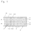
- a rectangular filter plate 3 is shown, the transverse to Folds 2 arranged in the longitudinal direction 4 in the first method step Pleats are generated.
- the width 13 of the filter plate 3 essentially corresponds to twice the width of the ready-to-use, annular filter insert 1, so that two partial filter plates 5, 6 can be produced from the filter plate 3 shown here, which are later assembled to form the annular filter insert 1 ,
- an edge is applied in a flow-tight manner to the two longitudinal sides 10.1, 10.2 of the filter plate 3 following the pleating.
- the edges 11.1, 11.2 form the outer circumference of the ready-to-use, ring-shaped filter insert and seal against a filter housing (not shown here).
- the filter plate 3 in the second method step in the longitudinal direction 4 was cut and the two partial filter plates 5, 6 formed are, in each case, as shown in FIG. 2, in the third method step laid the core 7.
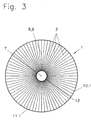
- the partial filter plates 5, 6 enclose the core 7, as in 3, shown completely, the first fold 8 being in the fourth method step and the last fold 9 of the respective partial filter plates 5, 6 with each other get connected.
- the connection is made, for example, by a Gluing or welding.
- the core 7 was in this embodiment with the outer circumference encased in a sealing material, the sealing material for example, be formed by a closed-cell foam can.
- the sealing material for example, be formed by a closed-cell foam can.
- the inner long side of the partial filter plates 5, 6 touch the Sealing material 12 to prevent a flow short between the Avoid upstream and downstream.
Landscapes
- Chemical & Material Sciences (AREA)
- Chemical Kinetics & Catalysis (AREA)
- Filtering Of Dispersed Particles In Gases (AREA)
- Filtration Of Liquid (AREA)
- Filtering Materials (AREA)
Abstract
Description
- Fig. 1
- die rechteckige Filterplatte nach dem ersten Verfahrensschritt und die Schnittlinie, entlang der die Filterplatte gemäß dem zweiten Verfahrensschritt durchtrennt wird,
- Fig. 2
- eine der Teil-Filterplatten, die gemäß drittem Verfahrensschritt um einen Kern gelegt wird und
- Fig. 3
- den gebrauchfertigen, kreisringförmig ausgebildeten Filtereinsatz nach Durchführung des vierten Verfahrensschritts.
Bevor die Filterplatte 3 im zweiten Verfahrensschritt in Längsrichtung 4 durchtrennt wird, um die beiden Teil-Filterplatten 5, 6 zu erhalten, wird auf die beiden Längsseiten 10.1, 10.2 der Filterplatte 3 im Anschluss an das Plissieren jeweils eine Kante strömungsdicht aufgebracht. Die Kanten 11.1, 11.2 bilden bei dem gebrauchsfertigen, ringförmigen Filtereinsatz den Außenumfang und dichten gegenüber einem hier nicht dargestellten Filtergehäuse ab.
Claims (9)
- Verfahren zur Herstellung eines Filtereinsatzes (1) mit sich in radialer Richtung erstreckenden Falten (2), wobei zunächst ein Filterwerkstoff zu einer im Wesentlichen rechteckigen Filterplatte (3) mit quer zur Längsrichtung (4) angeordneten Falten (2) plissiert wird, wobei die plissierte Filterplatte (3) dann um einen Kern (7) gelegt wird und wobei anschließend die einander in Umfangsrichtung benachbarte erste (8) und letzte Falte (9) der Filterplatte (3) miteinander verbunden werden.
- Verfahren zur Herstellung eines Filtereinsatzes (1) mit sich in radialer Richtung erstreckenden Falten (2), wobei in einem ersten Verfahrensschritt ein Filterwerkstoff zu einer im Wesentlichen rechteckigen Filterplatte (3) mit quer zur Längsrichtung (4) angeordneten Falten (2) plissiert wird, wobei die Filterplatte (3) in einem zweiten Verfahrensschritt in Längsrichtung (4) zumindest einmal durchtrennt wird, um zumindest zwei Teil-Filterplatten (5, 6) zu erhalten, wobei jede der Teil-Filterplatten (5, 6) in einem dritten Verfahrensschritt um einen Kern (7) gelegt wird und wobei in einem vierten Verfahrensschritt die einander in Umfangsrichtung benachbarte erste (8) und letzte Falte (9) jeder Teil-Filterplatte (5, 6) miteinander verbunden werden.
- Verfahren nach einem der Ansprüche 1 oder 2, dadurch gekennzeichnet, dass eine Längsseite (10) der Filterplatte (3) und / oder eine Längsseite der Teil-Filterplatten (5, 6) mit einer Kante (11) strömungsdicht verbunden werden.
- Verfahren nach einem der Ansprüche 2 oder 3, dadurch gekennzeichnet, dass beide Längsseiten (10.1, 10.2) der Filterplatte (3) im Anschluss an den ersten Verfahrensschritt mit jeweils einer Kante (11.1, 11.2) strömungsdicht verbunden werden.
- Verfahren nach einem der Ansprüche 1 bis 4, dadurch gekennzeichnet, dass der Kern (7) mit einem Dichtungswerkstoff (12) außenumfangsseitig ummantelt wird.
- Verfahren nach Anspruch 5, dadurch gekennzeichnet, dass als Dichtungswerkstoff (12) ein geschlossenzelliger Schaumstoff aufgespritzt wird.
- Verfahren nach einem der Ansprüche 1 bis 6, dadurch gekennzeichnet, dass der Kern (7) und die radial angrenzenden Stirnseiten der Falten (2) strömungsdicht verbunden werden.
- Verfahren nach einem der Ansprüche 1 bis 7, dadurch gekennzeichnet, dass der Kern (7) an die radial inneren Stirnseiten der Falten (2) strömungsdicht angeschäumt wird.
- Verfahren nach einem der Ansprüche 1 bis 8, dadurch gekennzeichnet, dass der Kern (7) und die radial inneren Stirnseiten der Falten (2) kraftund / oder formschlüssig verbunden werden.
Applications Claiming Priority (2)
| Application Number | Priority Date | Filing Date | Title |
|---|---|---|---|
| DE10061479A DE10061479B4 (de) | 2000-12-08 | 2000-12-08 | Verfahren zur Herstellung eines Filtereinsatzes |
| DE10061479 | 2000-12-08 |
Publications (2)
| Publication Number | Publication Date |
|---|---|
| EP1213045A1 true EP1213045A1 (de) | 2002-06-12 |
| EP1213045B1 EP1213045B1 (de) | 2006-05-31 |
Family
ID=7666561
Family Applications (1)
| Application Number | Title | Priority Date | Filing Date |
|---|---|---|---|
| EP01128684A Expired - Lifetime EP1213045B1 (de) | 2000-12-08 | 2001-12-01 | Verfahren zur Herstellung eines Filtereinsatzes |
Country Status (3)
| Country | Link |
|---|---|
| US (1) | US20020108701A1 (de) |
| EP (1) | EP1213045B1 (de) |
| DE (2) | DE10061479B4 (de) |
Families Citing this family (3)
| Publication number | Priority date | Publication date | Assignee | Title |
|---|---|---|---|---|
| CN108126394A (zh) * | 2018-01-03 | 2018-06-08 | 辜晓林 | 一种用于畜禽粪便固液分离机的滤筒 |
| EP3981491A1 (de) | 2020-10-08 | 2022-04-13 | Carl Freudenberg KG | Filteranordnung mit filterelement und filtergehäuse |
| EP3995199B1 (de) | 2020-11-05 | 2022-12-28 | Carl Freudenberg KG | Filter und luftreinigungsgerät |
Citations (4)
| Publication number | Priority date | Publication date | Assignee | Title |
|---|---|---|---|---|
| DE2842127A1 (de) * | 1977-10-27 | 1979-05-03 | Gilardini Spa | Filterpatrone |
| US4619675A (en) * | 1983-06-24 | 1986-10-28 | Midori Anzen Co., Ltd. | Filter for air cleaners |
| JPS63137720A (ja) * | 1986-12-01 | 1988-06-09 | Nippon Rokaki Kk | エアフイルタ |
| JPH07112109A (ja) * | 1993-10-19 | 1995-05-02 | Japan Vilene Co Ltd | 折り畳み式フィルタ |
Family Cites Families (15)
| Publication number | Priority date | Publication date | Assignee | Title |
|---|---|---|---|---|
| US2683537A (en) * | 1949-06-11 | 1954-07-13 | Fram Corp | Pleated filter element |
| US2599604A (en) * | 1949-07-13 | 1952-06-10 | Jordan V Bauer | Filter element |
| US3025963A (en) * | 1958-03-13 | 1962-03-20 | Russell H Curtis | Products useful as filtering devices and methods of making them |
| US3076555A (en) * | 1958-06-30 | 1963-02-05 | Tecalemit Ltd | Fluid filters |
| US3293830A (en) * | 1964-07-14 | 1966-12-27 | Ford Motor Co | Flame retarding induction system for an internal combustion engine |
| US3859068A (en) * | 1972-05-09 | 1975-01-07 | Tenneco Inc | Pleated air filter |
| JPS4987479U (de) * | 1972-11-15 | 1974-07-29 | ||
| US4186099A (en) * | 1977-02-11 | 1980-01-29 | All Services Enterprises, Inc. | Filter assembly with paper cartridge |
| US4422861A (en) * | 1982-02-05 | 1983-12-27 | American Optical Corporation | Aerosol filter cartridge |
| US4710297A (en) * | 1985-06-15 | 1987-12-01 | Kabushiki Kaisha Tsuchiya Seisakusho | Fluid filter with pleated filter medium |
| DE3728825A1 (de) * | 1986-08-28 | 1988-03-03 | Fuji Photo Film Co Ltd | Filterpatrone |
| GB2209354B (en) * | 1987-08-31 | 1991-10-30 | Tsuchiya Seisakusho | Filter medium forming system and process |
| US5618425A (en) * | 1993-04-30 | 1997-04-08 | Terumo Kabushiki Kaisha | Filtering apparatus with a pleated filtering element embedded in a filling material |
| DE19846916A1 (de) * | 1998-09-18 | 2000-03-23 | Juergen Pauls Konstruktionen S | Maschine zur Herstellung von Filtern |
| JP5042408B2 (ja) * | 1999-01-07 | 2012-10-03 | スリーエム イノベーティブ プロパティーズ カンパニー | プリーツ付フィルター要素 |
-
2000
- 2000-12-08 DE DE10061479A patent/DE10061479B4/de not_active Expired - Fee Related
-
2001
- 2001-12-01 DE DE50109940T patent/DE50109940D1/de not_active Expired - Fee Related
- 2001-12-01 EP EP01128684A patent/EP1213045B1/de not_active Expired - Lifetime
- 2001-12-07 US US10/013,123 patent/US20020108701A1/en not_active Abandoned
Patent Citations (4)
| Publication number | Priority date | Publication date | Assignee | Title |
|---|---|---|---|---|
| DE2842127A1 (de) * | 1977-10-27 | 1979-05-03 | Gilardini Spa | Filterpatrone |
| US4619675A (en) * | 1983-06-24 | 1986-10-28 | Midori Anzen Co., Ltd. | Filter for air cleaners |
| JPS63137720A (ja) * | 1986-12-01 | 1988-06-09 | Nippon Rokaki Kk | エアフイルタ |
| JPH07112109A (ja) * | 1993-10-19 | 1995-05-02 | Japan Vilene Co Ltd | 折り畳み式フィルタ |
Non-Patent Citations (2)
| Title |
|---|
| PATENT ABSTRACTS OF JAPAN vol. 12, no. 391 18 October 1988 (1988-10-18) * |
| PATENT ABSTRACTS OF JAPAN vol. 1995, no. 8 29 September 1995 (1995-09-29) * |
Also Published As
| Publication number | Publication date |
|---|---|
| DE10061479B4 (de) | 2007-08-02 |
| DE50109940D1 (de) | 2006-07-06 |
| DE10061479A1 (de) | 2002-08-01 |
| EP1213045B1 (de) | 2006-05-31 |
| US20020108701A1 (en) | 2002-08-15 |
Similar Documents
| Publication | Publication Date | Title |
|---|---|---|
| DE69712664T2 (de) | Dichtung mit eingebetteter Ringfeder | |
| DE3009436C2 (de) | ||
| DE102013019327B4 (de) | Filterelement mit Filterbalg und Verwendung des Filterelements | |
| EP3291909A1 (de) | Verfahren zum herstellen von filterbälgen | |
| DE69717554T2 (de) | Filteranordnung und Verfahren zu ihrer Herstellung | |
| DE69411182T2 (de) | Verbindungs- und dichtungsanordnung für luftleitungsrohre | |
| WO2004014516A1 (de) | Filterelement und verfahren zu dessen herstellung | |
| DE19804927C2 (de) | Luftreiniger | |
| DE102013004283A1 (de) | Verfahren und Vorrichtung zur Herstellung eines Filterelements und Filterelement | |
| DE102014015905A1 (de) | Flachfilterelement für Fluide und Verfahren und Vorrichtung zur Herstellung eines solchen | |
| DE69311869T2 (de) | Membranmodul und Verfahren zu seiner Herstellung | |
| DE102014009707A1 (de) | Filtermedium, Filterelement mit einem Filtermedium, Filtersystem und Verfahren zur Herstellung eines Filtermediums | |
| DE102006027500A1 (de) | Axialgleitlagerring | |
| EP3529468A1 (de) | Filter und verfahren zur herstellung eines filters | |
| DE10061479A1 (de) | Verfahren zur Herstellung eines Filtereinsatzes | |
| DE939864C (de) | Fluessigkeitsfilter aus Filterstoffstreifen | |
| EP2603302A1 (de) | Filtermattenbahn und daraus hergestelltes filterelement | |
| DE3320190C2 (de) | Trennwand zwischen einem Hochdruckbereich und einem axial benachbarten Niederdruckbereich eines Gasturbinentriebwerks | |
| DE102022125471A1 (de) | Filterelement und Filtervorrichtung | |
| DE4345132C2 (de) | Fluidfilter zur Verwendung in einem Fluidströmungskanal | |
| DE2408264B1 (de) | Auswechselbarer Filtereinsatz | |
| DE20310833U1 (de) | Filtereinsatz zum Einbau in einen Strömungskanal | |
| WO2022184577A1 (de) | Verfahren zur bildung eines filtermediums | |
| DE2403823A1 (de) | Rohr-t-element mit einem rohrstueck aus blech sowie verfahren zu dessen herstellung | |
| DE3618664A1 (de) | Einweg-kleinfilter zur filtration von fluiden |
Legal Events
| Date | Code | Title | Description |
|---|---|---|---|
| PUAI | Public reference made under article 153(3) epc to a published international application that has entered the european phase |
Free format text: ORIGINAL CODE: 0009012 |
|
| AK | Designated contracting states |
Kind code of ref document: A1 Designated state(s): AT BE CH CY DE DK ES FI FR GB GR IE IT LI LU MC NL PT SE TR |
|
| AX | Request for extension of the european patent |
Free format text: AL;LT;LV;MK;RO;SI |
|
| 17P | Request for examination filed |
Effective date: 20020418 |
|
| AKX | Designation fees paid |
Designated state(s): DE FR GB IT |
|
| GRAP | Despatch of communication of intention to grant a patent |
Free format text: ORIGINAL CODE: EPIDOSNIGR1 |
|
| GRAS | Grant fee paid |
Free format text: ORIGINAL CODE: EPIDOSNIGR3 |
|
| GRAA | (expected) grant |
Free format text: ORIGINAL CODE: 0009210 |
|
| AK | Designated contracting states |
Kind code of ref document: B1 Designated state(s): DE FR GB IT |
|
| PG25 | Lapsed in a contracting state [announced via postgrant information from national office to epo] |
Ref country code: IT Free format text: LAPSE BECAUSE OF FAILURE TO SUBMIT A TRANSLATION OF THE DESCRIPTION OR TO PAY THE FEE WITHIN THE PRESCRIBED TIME-LIMIT;WARNING: LAPSES OF ITALIAN PATENTS WITH EFFECTIVE DATE BEFORE 2007 MAY HAVE OCCURRED AT ANY TIME BEFORE 2007. THE CORRECT EFFECTIVE DATE MAY BE DIFFERENT FROM THE ONE RECORDED. Effective date: 20060531 Ref country code: GB Free format text: LAPSE BECAUSE OF FAILURE TO SUBMIT A TRANSLATION OF THE DESCRIPTION OR TO PAY THE FEE WITHIN THE PRESCRIBED TIME-LIMIT Effective date: 20060531 |
|
| REG | Reference to a national code |
Ref country code: GB Ref legal event code: FG4D Free format text: NOT ENGLISH |
|
| REF | Corresponds to: |
Ref document number: 50109940 Country of ref document: DE Date of ref document: 20060706 Kind code of ref document: P |
|
| GBV | Gb: ep patent (uk) treated as always having been void in accordance with gb section 77(7)/1977 [no translation filed] |
Effective date: 20060531 |
|
| PLBE | No opposition filed within time limit |
Free format text: ORIGINAL CODE: 0009261 |
|
| STAA | Information on the status of an ep patent application or granted ep patent |
Free format text: STATUS: NO OPPOSITION FILED WITHIN TIME LIMIT |
|
| EN | Fr: translation not filed | ||
| 26N | No opposition filed |
Effective date: 20070301 |
|
| PG25 | Lapsed in a contracting state [announced via postgrant information from national office to epo] |
Ref country code: FR Free format text: LAPSE BECAUSE OF FAILURE TO SUBMIT A TRANSLATION OF THE DESCRIPTION OR TO PAY THE FEE WITHIN THE PRESCRIBED TIME-LIMIT Effective date: 20070309 |
|
| PG25 | Lapsed in a contracting state [announced via postgrant information from national office to epo] |
Ref country code: FR Free format text: LAPSE BECAUSE OF FAILURE TO SUBMIT A TRANSLATION OF THE DESCRIPTION OR TO PAY THE FEE WITHIN THE PRESCRIBED TIME-LIMIT Effective date: 20060531 |
|
| PGFP | Annual fee paid to national office [announced via postgrant information from national office to epo] |
Ref country code: DE Payment date: 20081230 Year of fee payment: 8 |
|
| PG25 | Lapsed in a contracting state [announced via postgrant information from national office to epo] |
Ref country code: DE Free format text: LAPSE BECAUSE OF NON-PAYMENT OF DUE FEES Effective date: 20100701 |