EP1212138B1 - Sampling/dispensing device with plunger and housing set onto plunger - Google Patents
Sampling/dispensing device with plunger and housing set onto plunger Download PDFInfo
- Publication number
- EP1212138B1 EP1212138B1 EP00953322A EP00953322A EP1212138B1 EP 1212138 B1 EP1212138 B1 EP 1212138B1 EP 00953322 A EP00953322 A EP 00953322A EP 00953322 A EP00953322 A EP 00953322A EP 1212138 B1 EP1212138 B1 EP 1212138B1
- Authority
- EP
- European Patent Office
- Prior art keywords
- plunger
- drawn
- barrel
- housing
- moulding
- Prior art date
- Legal status (The legal status is an assumption and is not a legal conclusion. Google has not performed a legal analysis and makes no representation as to the accuracy of the status listed.)
- Expired - Lifetime
Links
Images


Classifications
-
- B—PERFORMING OPERATIONS; TRANSPORTING
- B01—PHYSICAL OR CHEMICAL PROCESSES OR APPARATUS IN GENERAL
- B01L—CHEMICAL OR PHYSICAL LABORATORY APPARATUS FOR GENERAL USE
- B01L3/00—Containers or dishes for laboratory use, e.g. laboratory glassware; Droppers
- B01L3/02—Burettes; Pipettes
- B01L3/021—Pipettes, i.e. with only one conduit for withdrawing and redistributing liquids
- B01L3/0217—Pipettes, i.e. with only one conduit for withdrawing and redistributing liquids of the plunger pump type
-
- G—PHYSICS
- G01—MEASURING; TESTING
- G01N—INVESTIGATING OR ANALYSING MATERIALS BY DETERMINING THEIR CHEMICAL OR PHYSICAL PROPERTIES
- G01N35/00—Automatic analysis not limited to methods or materials provided for in any single one of groups G01N1/00 - G01N33/00; Handling materials therefor
- G01N35/02—Automatic analysis not limited to methods or materials provided for in any single one of groups G01N1/00 - G01N33/00; Handling materials therefor using a plurality of sample containers moved by a conveyor system past one or more treatment or analysis stations
- G01N35/04—Details of the conveyor system
- G01N2035/0401—Sample carriers, cuvettes or reaction vessels
- G01N2035/0406—Individual bottles or tubes
- G01N2035/0408—Individual bottles or tubes connected in a flexible chain
-
- G—PHYSICS
- G01—MEASURING; TESTING
- G01N—INVESTIGATING OR ANALYSING MATERIALS BY DETERMINING THEIR CHEMICAL OR PHYSICAL PROPERTIES
- G01N35/00—Automatic analysis not limited to methods or materials provided for in any single one of groups G01N1/00 - G01N33/00; Handling materials therefor
- G01N35/10—Devices for transferring samples or any liquids to, in, or from, the analysis apparatus, e.g. suction devices, injection devices
- G01N35/1065—Multiple transfer devices
-
- Y—GENERAL TAGGING OF NEW TECHNOLOGICAL DEVELOPMENTS; GENERAL TAGGING OF CROSS-SECTIONAL TECHNOLOGIES SPANNING OVER SEVERAL SECTIONS OF THE IPC; TECHNICAL SUBJECTS COVERED BY FORMER USPC CROSS-REFERENCE ART COLLECTIONS [XRACs] AND DIGESTS
- Y10—TECHNICAL SUBJECTS COVERED BY FORMER USPC
- Y10T—TECHNICAL SUBJECTS COVERED BY FORMER US CLASSIFICATION
- Y10T436/00—Chemistry: analytical and immunological testing
- Y10T436/25—Chemistry: analytical and immunological testing including sample preparation
- Y10T436/2575—Volumetric liquid transfer
Definitions
- This invention relates to a positive displacement type substance sampler/dispenser.
- a plunger-type pipette is in common usage. It generally comprises an outer cylindrical housing having a central bore in which a plunger sits. The plunger can be slid within the bore to either dispense a substance, such as a fluid or particulate matter, from an orifice in one end of the housing or, if slid in the opposite direction, to draw a fluid or particulate matter into the housing.
- a dispenser has particular benefits in that it can draw up and dispense substances with a high degree of accuracy. Devices in current use do, however, have problems associated with them.
- the piston is typically slightly oversize for the bore such that it forms an interference fit for sealing.
- either the piston or the bore may be made from a compliant material. Examples are medical syringes having rigid polystyrene bores and rubber piston ends, or stiff polypropylene pistons with a compliant thin-walled bore.
- An alternative sealing arrangement is to provide a lip seal at the end of the piston.
- compliant materials cannot be used where chemical resistance is required; it becomes increasingly difficult to injection mould bores as the diameter is reduced such that devices capable of accurate dispensing over the nanolitre range are not possible; the need for a draft angle and conventional moulding techniques limits the practical length and thus the dynamic range of the pipette; and the manufacture of pistons with lip seals becomes increasingly difficult as the diameter is reduced below 1 mm.
- present methods of construction are not suited to long bore, high accuracy, low cost and sub-microlitre devices.
- the first material may be metal, plastic, ceramic or other suitable material.
- the plunger may be formed from drawn wire or extruded material to ensure that it has a uniform diameter.
- the housing may be moulded onto the plunger by injection moulding, welding, coextrusion, casting, dip coating etc.
- the materials may be selected such that, preferably, the material of the piston is stiffer and/or has a lower thermal expansion coefficient than the material of the bore. If heat is applied during manufacture, such as using molten plastic to form a bore around a metal wire, the bore will progressively tighten around the piston as the device cools down, thus forming a better seal. If the piston can be maintained at a lower temperature than the material of the bore during forming, it is possible to get further improved sealing because the piston will have expanded even less with respect to the bore.
- the piston may be actively cooled, or may exploit a higher thermal conductivity or specific heat capacity property than the material of the bore.
- the device may be attached or incorporated into a flexible strip or other backing to which further devices are attached for ease of automated handling.
- the flexible strip may have sprocket holes to drive and align the pipettes.
- the devices may be manufactured as single discrete pipettes.
- the pipettes are operated by gripping both the plunger housing and plunger of the pipette and moving the plunger within the bore in the same way as a conventional positive displacement pipette. This operation may be performed by a manual or automatic device.
- the devices may be used singly or in multiples with or without a backing strip.
- the material of the strip may itself form part or all of the housing of the device.
- the device may be formed so that it has a heat sealable tip, allowing for the loading of the apparatus with a substance, the substance being sealed in place by sealing of the tip.
- the device may also be incorporated into fluidic devices such as "chip-based" analytical devices, chemical synthesizers and sensors to provide a means of forming capillaries, valves and pumps, for example.
- fluidic devices such as "chip-based” analytical devices, chemical synthesizers and sensors to provide a means of forming capillaries, valves and pumps, for example.
- the device may have plural plungers arranged on different axes and each sliding within a different region of the housing, the different regions of the housing being joined at a central common core adjacent to an aperture.
- such a device By forming the housing around the plunger the cost of manufacture of the device is reduced considerably. Furthermore, such a device has a highly effective seal between the plunger and the housing, and can also be ensured of having a uniform cylindrical wall, even if it is arranged for the dispensing/sampling of very small samples.
- the device may be formed by moulding the bore round a drawn wire such that it produces a pipette with a perfectly cylindrical bore throughout.
- the drawn wire may be projected beyond the tip of the device to pierce the seal of a storage vessel or to act as an ultrasonic probe or electrode for automatic level sensing.
- a second conductor may be provided parallel to the piston to act as a counter electrode.
- the bore may be formed around a piston which has had its tip ground to a shaped point. This provides for an aperture that is a smaller diameter than the bore at the tip of the device, which is important for retaining liquid in larger bore devices.
- a prior art positive displacement-type pipette has an outer housing 1 which has a plunger 2 slidably retained therein.
- the plunger 2 can be moved to draw a sample into the housing 1 or expel a sample from the housing 1 via an aperture 3.
- the plunger 2 has a head 4 formed from relatively hard material and which is resilient enough to compensate for a variation in housing diameter with respect to the position of the plunger 2 within the housing.
- FIG. 2 is a side cross-sectional view of a device 10 in accordance with the present invention during manufacture.
- the device 10 has a central plunger 12, in this example formed from drawn metal, and an outer housing 11.
- the outer housing 11 is moulded onto the plunger 12.
- a thermoplastic for example, polyethylene or polypropylene
- the plunger should be formed from a material with a higher melting point and preferably lower thermal expansion coefficient than the housing.
- the plunger may for example, be made of metal, glass, plastic or ceramic.
- the housing may also be formed from a thermoset material (for example, silicone rubber or polyurethane resin) or a thermoplastic dissolved in solvent (for example polycarbonate or polyvinylchloride in solvent) in which case the plunger material need not have a higher melting point than the housing. It is preferable to use a thermoset that shrinks on curing.
- a thermoset material for example, silicone rubber or polyurethane resin
- a thermoplastic dissolved in solvent for example polycarbonate or polyvinylchloride in solvent
- the housing 11 may be formed by injection moulding, extrusion, or any other well known casting, ultrasonic, welding, dip-coating, co-extrusion, powder coating, thermoforming, spraying forming technique. Once the housing 11 has cooled and set the device can be trimmed to length.
- the plunger 12 can be drawn into the housing, leaving an aperture 13 and an inner core 14 into which a sample can be drawn during use.
- the inner core 14 is a uniform cylinder as it corresponds to the outer surface of the plunger 12. Furthermore, it is in extremely close engagement with the plunger 12 because of the moulding techniques employed.
- Figure 4 shows how the device 10 of the present invention may be attached to one or more flexible strips 15 for ease of handling. In particular, such an arrangement is handled very easily by automated machinery. In practice, because of the extremely low cost nature of the manufacture of the device 10, it can be treated as a disposable item in use.
- the housing 11 may be formed over the end of the plunger 12 and arranged so that, in use, it has a frangible region which can be snapped off just prior to device use to prevent contamination of the plunger end.
- the device 10 may be provided with a heat sealable region adjacent to the aperture 13, so that a substance can be placed in the core 14 of the device 10 and sealed therein. This provides a sealed device that, once the end is cropped off, can meter and deliver the contents without loss.
- FIG. 5 A further alternative arrangement is shown in Figure 5.
- plural plungers 12 have a outer housing 11 formed thereon. All of the plungers 12 are able to access a common core 14 and tip 13.
- capillary paths are created in the device. Liquid can be drawn up and moved through the system very precisely by moving the pistons. Where capillaries intersect the pistons may be operated as active valves to stop or regulate flow.
- a viewing window (not shown) may be incorporated into devices to allow the contents to be analysed by a detector.
- Such an arrangement provides for an extremely cost effective multiple sample withdrawal and dispensing arrangement that still has an high degree of sampling/dispensing accuracy and extremely low leakage.
- Figure 4 shows a device constructed according to the present invention.
- Hard drawn and polished stainless steel wire (British Standard 2056 302S26) of 0.40 mm diameter is inserted into high density polyethylene (HDPE) tubing of 0.43 mm ID and 0.66 mm OD.
- the tubing length is chosen as 23 mm and the wire length as 30 mm, to leave 7 mm of wire protruding.
- This tubing is placed across a tape 30 mm wide, made of 0.175 mm polypropylene film.
- the tubing with wire insert is then welded onto the backing tape using a hemi-cylindrical ultrasonic weld horn along the length of the plastic tube. This applies pressure and melts the plastic tube such that the tube material flows around the wire. This eliminates the 0.03 mm clearance between the wire and the tubing stock.
- a pipette is thus formed and is simultaneously welded to the backing film in one operation. Multiple pipettes can be formed in a continuous step-and-repeat process.
- the tape can then be die-cut to crop the tubing and wire to form the pipette shapes and sprocket holes 16 in one operation.
- the backing tape is cut to provide slender pipettes.
- Pipettes may be cut from the backing tape and used singly, or may be retained on the backing tape and used in multiples.
- the backing tape pitch was chosen to be a multiple of 2.25 mm (in this case 4.5 mm) to match the pitch of standard 96, 384 and 1536-well microtitre plates.
- An aspirate/dispense head can be constructed to grip the backing tape or barrel and pistons independently, and to drive the pistons up and down under user or automatic control to achieve metering(not shown).
- Volumetric accuracy trials were performed with the prototype device by aspirating 100, 200, 300, 400 and 500 nl samples of writing inks and dispensing them into dry receptacles with tipping off. The results were determined gravimetrically and are shown in figure 7. This shows that even non-optimised devices following this invention are capable of accurately aspirating and dispensing samples as small as 100 nl.
- the advantage of this approach for storage is that all of the material stored can be recovered and the storage device can also be used to meter and dispense the stored sample.
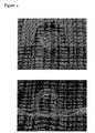
- Figure 8 shows a photomicrograph of a cross-section of a pipette made by the process of example 1.
- the 0.3 mm diameter wire has been withdrawn.
- the out-of-round distortion was caused by the blade used to cut the section.
- the device On re-inserting the wire plunger the device assumes a circular cross-section.
- a further device was made by the method above, but using polyethylene-coated PET film for the backing tape.
- the PET layer provides a stiffer backing tape more suited for mechanical feed.
- a device according to present invention was constructed by insert moulding 0.5 mm diameter stainless steel wire into mould-making grade silicone rubber.
- a mould was made from three 3 mm thick aluminium sheets sandwiched between two 1 mm thick sheets of glass such that a void 100 mm long, 20 mm high and 3 mm thick was formed. The assembly was held together with spring clips and the top of this void was open to allow filling with resin.
- An array of stainless steel wires was suspended above the mould with the ends of the wires protruding to the bottom of the mould. Silicone resin was poured into the mould and allowed to cure. Once set, the clips were released and the glass sides taken off the mould to allow the device to be removed. After shaping the pipettes with a knife the wires were cropped to length to form pistons. Operation of the resulting prototype demonstrated suitable function as a pipette.
- a device according to the present invention was constructed by sandwiching stainless steel entomology pins (0.38 mm diameter, 38 mm long, size 00) between polypropylene tapes 0.2 mm thick by 30 mm wide 300 mm long.
- the pins were laid across one plastics material and the second plastic tape was over-laid to form a sandwich.
- the plastic sheets were joined together and heat-welded around and along the length of each individual pin between two hemi-cylindrical heated formers. This caused the polypropylene to flow around the pins, thus forming a barrel around each piston.
- the tape was then cut to form an array of pipettes following the method of Example 1.
- a stiff stainless steel wire of 0.4 mm diameter (EN304, BS1554 or similar) was coated with an extruded polyethylene (PE) sheath to give an overall diameter of 0.80 mm.
- PE polyethylene
- a backing strip was formed by cutting polyester/Surlyn/EVA film (thickness 125 ⁇ m overall) to form a carrier tape with tabs along one edge and sprocket holes for transport (figure 4). Pipettes were ultrasonically welded to this carrier tape at 4.5 mm intervals. Strips of pipettes or individual pipettes can be cut off this carrier tape for subsequent use.
Landscapes
- Health & Medical Sciences (AREA)
- Clinical Laboratory Science (AREA)
- Chemical & Material Sciences (AREA)
- Chemical Kinetics & Catalysis (AREA)
- Devices For Use In Laboratory Experiments (AREA)
- Sampling And Sample Adjustment (AREA)
- Automatic Analysis And Handling Materials Therefor (AREA)
- Feeding, Discharge, Calcimining, Fusing, And Gas-Generation Devices (AREA)
- Physical Or Chemical Processes And Apparatus (AREA)
- Apparatus Associated With Microorganisms And Enzymes (AREA)
- Processing And Handling Of Plastics And Other Materials For Molding In General (AREA)
- Analysing Materials By The Use Of Radiation (AREA)
- Application Of Or Painting With Fluid Materials (AREA)
- Laminated Bodies (AREA)
Priority Applications (1)
| Application Number | Priority Date | Filing Date | Title |
|---|---|---|---|
| EP00953322A EP1212138B1 (en) | 1999-08-17 | 2000-08-15 | Sampling/dispensing device with plunger and housing set onto plunger |
Applications Claiming Priority (4)
| Application Number | Priority Date | Filing Date | Title |
|---|---|---|---|
| EP99306463 | 1999-08-17 | ||
| EP99306463 | 1999-08-17 | ||
| EP00953322A EP1212138B1 (en) | 1999-08-17 | 2000-08-15 | Sampling/dispensing device with plunger and housing set onto plunger |
| PCT/GB2000/003142 WO2001012329A1 (en) | 1999-08-17 | 2000-08-15 | Sampling/dispensing device with plunger and housing set onto plunger |
Publications (2)
| Publication Number | Publication Date |
|---|---|
| EP1212138A1 EP1212138A1 (en) | 2002-06-12 |
| EP1212138B1 true EP1212138B1 (en) | 2005-06-08 |
Family
ID=8241581
Family Applications (2)
| Application Number | Title | Priority Date | Filing Date |
|---|---|---|---|
| EP00953322A Expired - Lifetime EP1212138B1 (en) | 1999-08-17 | 2000-08-15 | Sampling/dispensing device with plunger and housing set onto plunger |
| EP00953324A Expired - Lifetime EP1206321B1 (en) | 1999-08-17 | 2000-08-15 | Flexible pipette strip and method of its use |
Family Applications After (1)
| Application Number | Title | Priority Date | Filing Date |
|---|---|---|---|
| EP00953324A Expired - Lifetime EP1206321B1 (en) | 1999-08-17 | 2000-08-15 | Flexible pipette strip and method of its use |
Country Status (7)
| Country | Link |
|---|---|
| US (1) | US7709268B1 (enExample) |
| EP (2) | EP1212138B1 (enExample) |
| JP (2) | JP4700245B2 (enExample) |
| AT (2) | ATE297252T1 (enExample) |
| AU (2) | AU6583800A (enExample) |
| DE (2) | DE60020722T2 (enExample) |
| WO (2) | WO2001012329A1 (enExample) |
Cited By (1)
| Publication number | Priority date | Publication date | Assignee | Title |
|---|---|---|---|---|
| US8273009B2 (en) | 2008-03-07 | 2012-09-25 | Cook Medical Technologies Llc | Pipette aspiration device |
Families Citing this family (20)
| Publication number | Priority date | Publication date | Assignee | Title |
|---|---|---|---|---|
| US7402282B2 (en) | 2001-07-20 | 2008-07-22 | Ortho-Clinical Diagnostics, Inc. | Auxiliary sample supply for a clinical analyzer |
| US7459127B2 (en) | 2002-02-26 | 2008-12-02 | Siemens Healthcare Diagnostics Inc. | Method and apparatus for precise transfer and manipulation of fluids by centrifugal and/or capillary forces |
| US7094354B2 (en) | 2002-12-19 | 2006-08-22 | Bayer Healthcare Llc | Method and apparatus for separation of particles in a microfluidic device |
| US7125711B2 (en) | 2002-12-19 | 2006-10-24 | Bayer Healthcare Llc | Method and apparatus for splitting of specimens into multiple channels of a microfluidic device |
| US7435381B2 (en) | 2003-05-29 | 2008-10-14 | Siemens Healthcare Diagnostics Inc. | Packaging of microfluidic devices |
| US7347617B2 (en) | 2003-08-19 | 2008-03-25 | Siemens Healthcare Diagnostics Inc. | Mixing in microfluidic devices |
| GB0420256D0 (en) | 2004-09-13 | 2004-10-13 | Cassells John M | Method and apparatus for sampling and analysis of fluids |
| ES2547861T3 (es) * | 2007-01-12 | 2015-10-09 | Lbt Innovations Limited | Un cartucho aplicador de veteado y un sistema para unir el mismo a un aparato de veteado |
| CN101636482B (zh) | 2007-01-12 | 2013-11-13 | 实验室技术系统有限公司 | 用于定向固体生长培养基板的方法和装置 |
| EP2099894B1 (en) * | 2007-01-12 | 2019-04-10 | Autobio Diagnostics Co., Ltd. | Method and apparatus for locating the surface of solid growth culture media in a plate |
| EP2099896B1 (en) | 2007-01-12 | 2019-09-04 | Autobio Diagnostics Co., Ltd. | Method and apparatus for inoculating and streaking a medium in a plate |
| JP4942181B2 (ja) * | 2007-02-20 | 2012-05-30 | セイコーインスツル株式会社 | 物質供給プローブ装置及び走査型プローブ顕微鏡 |
| US20110275536A1 (en) | 2009-01-30 | 2011-11-10 | Pronota N.V. | Biomarker for diagnosis, prediction and/or prognosis of acute heart failure and uses thereof |
| NO2491401T3 (enExample) | 2009-10-21 | 2018-11-03 | ||
| US9459272B2 (en) | 2010-03-22 | 2016-10-04 | BioNex Solutions, Inc. | Transfer or interrogation of materials by carrier and receiving devices moving independently and simultaneously on multiple axes |
| EP2924439B1 (en) | 2010-03-26 | 2017-02-01 | MyCartis N.V. | Ltbp2 as a biomarker for predicting or prognosticating mortality |
| AU2011240039B2 (en) | 2010-04-13 | 2017-01-19 | Mycartis Nv | Biomarkers for hypertensive disorders of pregnancy |
| CN108267330B (zh) * | 2018-04-25 | 2023-06-23 | 东北林业大学 | 一种小动物体表依附生物样本快速采样装置及方法 |
| EP3902396A4 (en) | 2018-12-28 | 2022-11-30 | Overture Life, Inc | CRYOSTORY DEVICE FOR OOCYTES AND EMBRYOS DURING CRYOPRESERVATION |
| US12382952B2 (en) | 2021-03-23 | 2025-08-12 | Overture Life, Inc. | Cryostorage device |
Family Cites Families (19)
| Publication number | Priority date | Publication date | Assignee | Title |
|---|---|---|---|---|
| US3766785A (en) * | 1971-05-17 | 1973-10-23 | Analytical Prod | Automatic pipette |
| US3852875A (en) * | 1973-01-05 | 1974-12-10 | Southwire Co | High speed tandem wire drawing and insulation system |
| US3877310A (en) * | 1973-03-05 | 1975-04-15 | Varian Associates | Automatic sampler apparatus |
| US3882665A (en) * | 1974-02-19 | 1975-05-13 | Bethlehem Steel Corp | Flexible pumping strand and method of making |
| DE2541642C3 (de) * | 1975-09-18 | 1979-07-26 | Labora Mannheim Gmbh Fuer Labortechnik, 6800 Mannheim | Pipertier-Handpipette |
| FI52025C (fi) * | 1976-04-08 | 1977-06-10 | Osmo Antero Suovaniemi | Menetelmä ja laitteisto nesteannosteluun, nesteen siirtoon ja laimennu ssarjoihin. |
| US4131112A (en) * | 1976-12-21 | 1978-12-26 | Ovutime, Inc. | Probe for obtaining sample of cervical mucus |
| US4121739A (en) * | 1977-04-20 | 1978-10-24 | Illinois Tool Works Inc. | Dispenser with unitary plunger and seal construction |
| US4662545A (en) * | 1984-01-05 | 1987-05-05 | Drummond Scientific Company | Disposable capillary tube device |
| JPS61137721A (ja) * | 1984-12-10 | 1986-06-25 | Kanda Rubber Kagaku Kk | ベロ−ズピペット等の製造方法 |
| CH671526A5 (enExample) | 1985-12-17 | 1989-09-15 | Hamilton Bonaduz Ag | |
| JPS63135225A (ja) * | 1986-11-27 | 1988-06-07 | Mochida Pharmaceut Co Ltd | 液体マイクロ定量インジエクシヨン成形製ピペツトの製造方法 |
| EP0443227A1 (en) | 1990-02-19 | 1991-08-28 | Ito Corporation | Analytical microsyringe |
| GB2249172A (en) * | 1990-10-26 | 1992-04-29 | N Proizv Ob Biolog Priborostro | Multichannel pipette |
| WO1992020778A1 (en) * | 1991-05-24 | 1992-11-26 | Kindconi Pty Limited | Biochemical reaction control |
| DE4433198C1 (de) * | 1994-09-17 | 1996-06-13 | Gaplast Ges Fuer Kunststoffver | Applikator |
| US6103198A (en) * | 1997-09-24 | 2000-08-15 | Sorenson Bioscience, Inc. | Micropipette tip strip and method |
| BR9814604A (pt) * | 1997-12-31 | 2000-10-17 | Qiagen Genomics Inc | "ponteiras em fase sólida e seus usos" |
| US6063339A (en) * | 1998-01-09 | 2000-05-16 | Cartesian Technologies, Inc. | Method and apparatus for high-speed dot array dispensing |
-
2000
- 2000-08-15 EP EP00953322A patent/EP1212138B1/en not_active Expired - Lifetime
- 2000-08-15 JP JP2001516665A patent/JP4700245B2/ja not_active Expired - Lifetime
- 2000-08-15 WO PCT/GB2000/003142 patent/WO2001012329A1/en not_active Ceased
- 2000-08-15 AU AU65838/00A patent/AU6583800A/en not_active Abandoned
- 2000-08-15 DE DE60020722T patent/DE60020722T2/de not_active Expired - Lifetime
- 2000-08-15 JP JP2001516666A patent/JP4425512B2/ja not_active Expired - Lifetime
- 2000-08-15 US US10/049,488 patent/US7709268B1/en not_active Expired - Lifetime
- 2000-08-15 AU AU65836/00A patent/AU6583600A/en not_active Abandoned
- 2000-08-15 DE DE60012752T patent/DE60012752T2/de not_active Expired - Lifetime
- 2000-08-15 AT AT00953322T patent/ATE297252T1/de not_active IP Right Cessation
- 2000-08-15 WO PCT/GB2000/003145 patent/WO2001012330A1/en not_active Ceased
- 2000-08-15 EP EP00953324A patent/EP1206321B1/en not_active Expired - Lifetime
- 2000-08-15 AT AT00953324T patent/ATE272446T1/de not_active IP Right Cessation
Cited By (1)
| Publication number | Priority date | Publication date | Assignee | Title |
|---|---|---|---|---|
| US8273009B2 (en) | 2008-03-07 | 2012-09-25 | Cook Medical Technologies Llc | Pipette aspiration device |
Also Published As
| Publication number | Publication date |
|---|---|
| EP1212138A1 (en) | 2002-06-12 |
| DE60020722D1 (de) | 2005-07-14 |
| US7709268B1 (en) | 2010-05-04 |
| EP1206321A1 (en) | 2002-05-22 |
| DE60012752T2 (de) | 2005-08-04 |
| DE60020722T2 (de) | 2006-05-04 |
| WO2001012330A1 (en) | 2001-02-22 |
| WO2001012329A1 (en) | 2001-02-22 |
| JP4700245B2 (ja) | 2011-06-15 |
| AU6583800A (en) | 2001-03-13 |
| AU6583600A (en) | 2001-03-13 |
| EP1206321B1 (en) | 2004-08-04 |
| JP4425512B2 (ja) | 2010-03-03 |
| ATE272446T1 (de) | 2004-08-15 |
| DE60012752D1 (de) | 2004-09-09 |
| JP2003507694A (ja) | 2003-02-25 |
| JP2003507163A (ja) | 2003-02-25 |
| ATE297252T1 (de) | 2005-06-15 |
Similar Documents
| Publication | Publication Date | Title |
|---|---|---|
| EP1212138B1 (en) | Sampling/dispensing device with plunger and housing set onto plunger | |
| US7258253B2 (en) | Method and system for precise dispensation of a liquid | |
| US7785466B1 (en) | Membrane filtered pipette tip | |
| US8124029B2 (en) | Apparatus and methods for microfluidic applications | |
| JP4607202B2 (ja) | マイクロウェル・アレイ内の物質のスクリーリングの方法 | |
| US5580529A (en) | Aerosol and liquid transfer resistant pipette tip apparatus | |
| WO1993024232A1 (en) | Calibrated pipette tip and method | |
| EP1707267A1 (en) | Device having a self sealing fluid port | |
| AU2012228096A1 (en) | Capillary fluid flow control | |
| US5494828A (en) | Slide dispensing device and method | |
| JP2003535350A (ja) | 試料保持具 | |
| US8313476B2 (en) | Sampling needle and methods of forming and using same | |
| US5674052A (en) | Pinch pump having selectable pressure plate sizes and a flexible tube with attachment ribs | |
| US7252212B2 (en) | Long-term liquid storage and dispensing system | |
| EP1710016A2 (en) | Device having a self sealing fluid port | |
| US20230375394A1 (en) | Fluid dispenser volume calibration device | |
| EP2945740B1 (en) | Disposable cartridge for microfluidics systems | |
| AU2002352349B2 (en) | Apparatus and methods for microfluidic applications |
Legal Events
| Date | Code | Title | Description |
|---|---|---|---|
| PUAI | Public reference made under article 153(3) epc to a published international application that has entered the european phase |
Free format text: ORIGINAL CODE: 0009012 |
|
| 17P | Request for examination filed |
Effective date: 20020308 |
|
| AK | Designated contracting states |
Kind code of ref document: A1 Designated state(s): AT BE CH CY DE DK ES FI FR GB GR IE IT LI LU MC NL PT SE |
|
| AX | Request for extension of the european patent |
Free format text: AL;LT;LV;MK;RO;SI |
|
| RIN1 | Information on inventor provided before grant (corrected) |
Inventor name: CASSELLS, JOHN, THE TECHNOLOGY PARTNERSHIP PLC Inventor name: MOUNTENEY, NICHOLAS IAN Inventor name: AVISON, GERALD Inventor name: EDWARDS, THOMAS RICHARD KERBY |
|
| 17Q | First examination report despatched |
Effective date: 20021015 |
|
| GRAP | Despatch of communication of intention to grant a patent |
Free format text: ORIGINAL CODE: EPIDOSNIGR1 |
|
| RAP1 | Party data changed (applicant data changed or rights of an application transferred) |
Owner name: TTP LABTECH LIMITED |
|
| GRAS | Grant fee paid |
Free format text: ORIGINAL CODE: EPIDOSNIGR3 |
|
| GRAA | (expected) grant |
Free format text: ORIGINAL CODE: 0009210 |
|
| AK | Designated contracting states |
Kind code of ref document: B1 Designated state(s): AT BE CH CY DE DK ES FI FR GB GR IE IT LI LU MC NL PT SE |
|
| PG25 | Lapsed in a contracting state [announced via postgrant information from national office to epo] |
Ref country code: IT Free format text: LAPSE BECAUSE OF FAILURE TO SUBMIT A TRANSLATION OF THE DESCRIPTION OR TO PAY THE FEE WITHIN THE PRESCRIBED TIME-LIMIT;WARNING: LAPSES OF ITALIAN PATENTS WITH EFFECTIVE DATE BEFORE 2007 MAY HAVE OCCURRED AT ANY TIME BEFORE 2007. THE CORRECT EFFECTIVE DATE MAY BE DIFFERENT FROM THE ONE RECORDED. Effective date: 20050608 Ref country code: AT Free format text: LAPSE BECAUSE OF FAILURE TO SUBMIT A TRANSLATION OF THE DESCRIPTION OR TO PAY THE FEE WITHIN THE PRESCRIBED TIME-LIMIT Effective date: 20050608 Ref country code: BE Free format text: LAPSE BECAUSE OF FAILURE TO SUBMIT A TRANSLATION OF THE DESCRIPTION OR TO PAY THE FEE WITHIN THE PRESCRIBED TIME-LIMIT Effective date: 20050608 Ref country code: LI Free format text: LAPSE BECAUSE OF FAILURE TO SUBMIT A TRANSLATION OF THE DESCRIPTION OR TO PAY THE FEE WITHIN THE PRESCRIBED TIME-LIMIT Effective date: 20050608 Ref country code: FI Free format text: LAPSE BECAUSE OF FAILURE TO SUBMIT A TRANSLATION OF THE DESCRIPTION OR TO PAY THE FEE WITHIN THE PRESCRIBED TIME-LIMIT Effective date: 20050608 Ref country code: NL Free format text: LAPSE BECAUSE OF FAILURE TO SUBMIT A TRANSLATION OF THE DESCRIPTION OR TO PAY THE FEE WITHIN THE PRESCRIBED TIME-LIMIT Effective date: 20050608 Ref country code: CH Free format text: LAPSE BECAUSE OF FAILURE TO SUBMIT A TRANSLATION OF THE DESCRIPTION OR TO PAY THE FEE WITHIN THE PRESCRIBED TIME-LIMIT Effective date: 20050608 Ref country code: ES Free format text: LAPSE BECAUSE OF FAILURE TO SUBMIT A TRANSLATION OF THE DESCRIPTION OR TO PAY THE FEE WITHIN THE PRESCRIBED TIME-LIMIT Effective date: 20050608 |
|
| REG | Reference to a national code |
Ref country code: GB Ref legal event code: FG4D |
|
| REG | Reference to a national code |
Ref country code: CH Ref legal event code: EP |
|
| REF | Corresponds to: |
Ref document number: 60020722 Country of ref document: DE Date of ref document: 20050714 Kind code of ref document: P |
|
| REG | Reference to a national code |
Ref country code: IE Ref legal event code: FG4D |
|
| PG25 | Lapsed in a contracting state [announced via postgrant information from national office to epo] |
Ref country code: LU Free format text: LAPSE BECAUSE OF NON-PAYMENT OF DUE FEES Effective date: 20050815 Ref country code: IE Free format text: LAPSE BECAUSE OF NON-PAYMENT OF DUE FEES Effective date: 20050815 Ref country code: CY Free format text: LAPSE BECAUSE OF FAILURE TO SUBMIT A TRANSLATION OF THE DESCRIPTION OR TO PAY THE FEE WITHIN THE PRESCRIBED TIME-LIMIT Effective date: 20050815 |
|
| PGFP | Annual fee paid to national office [announced via postgrant information from national office to epo] |
Ref country code: CH Payment date: 20050830 Year of fee payment: 6 |
|
| PG25 | Lapsed in a contracting state [announced via postgrant information from national office to epo] |
Ref country code: MC Free format text: LAPSE BECAUSE OF NON-PAYMENT OF DUE FEES Effective date: 20050831 |
|
| PG25 | Lapsed in a contracting state [announced via postgrant information from national office to epo] |
Ref country code: GR Free format text: LAPSE BECAUSE OF FAILURE TO SUBMIT A TRANSLATION OF THE DESCRIPTION OR TO PAY THE FEE WITHIN THE PRESCRIBED TIME-LIMIT Effective date: 20050908 Ref country code: DK Free format text: LAPSE BECAUSE OF FAILURE TO SUBMIT A TRANSLATION OF THE DESCRIPTION OR TO PAY THE FEE WITHIN THE PRESCRIBED TIME-LIMIT Effective date: 20050908 Ref country code: SE Free format text: LAPSE BECAUSE OF FAILURE TO SUBMIT A TRANSLATION OF THE DESCRIPTION OR TO PAY THE FEE WITHIN THE PRESCRIBED TIME-LIMIT Effective date: 20050908 |
|
| PG25 | Lapsed in a contracting state [announced via postgrant information from national office to epo] |
Ref country code: PT Free format text: LAPSE BECAUSE OF FAILURE TO SUBMIT A TRANSLATION OF THE DESCRIPTION OR TO PAY THE FEE WITHIN THE PRESCRIBED TIME-LIMIT Effective date: 20051114 |
|
| NLV1 | Nl: lapsed or annulled due to failure to fulfill the requirements of art. 29p and 29m of the patents act | ||
| REG | Reference to a national code |
Ref country code: CH Ref legal event code: PL |
|
| ET | Fr: translation filed | ||
| PLBE | No opposition filed within time limit |
Free format text: ORIGINAL CODE: 0009261 |
|
| STAA | Information on the status of an ep patent application or granted ep patent |
Free format text: STATUS: NO OPPOSITION FILED WITHIN TIME LIMIT |
|
| REG | Reference to a national code |
Ref country code: IE Ref legal event code: MM4A |
|
| 26N | No opposition filed |
Effective date: 20060309 |
|
| PGFP | Annual fee paid to national office [announced via postgrant information from national office to epo] |
Ref country code: FR Payment date: 20110901 Year of fee payment: 12 |
|
| REG | Reference to a national code |
Ref country code: FR Ref legal event code: ST Effective date: 20130430 |
|
| PG25 | Lapsed in a contracting state [announced via postgrant information from national office to epo] |
Ref country code: FR Free format text: LAPSE BECAUSE OF NON-PAYMENT OF DUE FEES Effective date: 20120831 |
|
| PGFP | Annual fee paid to national office [announced via postgrant information from national office to epo] |
Ref country code: DE Payment date: 20191022 Year of fee payment: 20 |
|
| PGFP | Annual fee paid to national office [announced via postgrant information from national office to epo] |
Ref country code: GB Payment date: 20191024 Year of fee payment: 20 |
|
| REG | Reference to a national code |
Ref country code: DE Ref legal event code: R071 Ref document number: 60020722 Country of ref document: DE |
|
| REG | Reference to a national code |
Ref country code: GB Ref legal event code: PE20 Expiry date: 20200814 |
|
| PG25 | Lapsed in a contracting state [announced via postgrant information from national office to epo] |
Ref country code: GB Free format text: LAPSE BECAUSE OF EXPIRATION OF PROTECTION Effective date: 20200814 |