EP1211210A2 - Einrichtung zur Perforation von Materialbahnen - Google Patents
Einrichtung zur Perforation von Materialbahnen Download PDFInfo
- Publication number
- EP1211210A2 EP1211210A2 EP01126464A EP01126464A EP1211210A2 EP 1211210 A2 EP1211210 A2 EP 1211210A2 EP 01126464 A EP01126464 A EP 01126464A EP 01126464 A EP01126464 A EP 01126464A EP 1211210 A2 EP1211210 A2 EP 1211210A2
- Authority
- EP
- European Patent Office
- Prior art keywords
- perforating
- tool
- elements
- perforating tool
- copy
- Prior art date
- Legal status (The legal status is an assumption and is not a legal conclusion. Google has not performed a legal analysis and makes no representation as to the accuracy of the status listed.)
- Withdrawn
Links
Images


Classifications
-
- B—PERFORMING OPERATIONS; TRANSPORTING
- B65—CONVEYING; PACKING; STORING; HANDLING THIN OR FILAMENTARY MATERIAL
- B65H—HANDLING THIN OR FILAMENTARY MATERIAL, e.g. SHEETS, WEBS, CABLES
- B65H45/00—Folding thin material
- B65H45/12—Folding articles or webs with application of pressure to define or form crease lines
- B65H45/28—Folding in combination with cutting
-
- B—PERFORMING OPERATIONS; TRANSPORTING
- B65—CONVEYING; PACKING; STORING; HANDLING THIN OR FILAMENTARY MATERIAL
- B65H—HANDLING THIN OR FILAMENTARY MATERIAL, e.g. SHEETS, WEBS, CABLES
- B65H2301/00—Handling processes for sheets or webs
- B65H2301/50—Auxiliary process performed during handling process
- B65H2301/51—Modifying a characteristic of handled material
- B65H2301/515—Cutting handled material
- B65H2301/5152—Cutting partially, e.g. perforating
-
- Y—GENERAL TAGGING OF NEW TECHNOLOGICAL DEVELOPMENTS; GENERAL TAGGING OF CROSS-SECTIONAL TECHNOLOGIES SPANNING OVER SEVERAL SECTIONS OF THE IPC; TECHNICAL SUBJECTS COVERED BY FORMER USPC CROSS-REFERENCE ART COLLECTIONS [XRACs] AND DIGESTS
- Y10—TECHNICAL SUBJECTS COVERED BY FORMER USPC
- Y10T—TECHNICAL SUBJECTS COVERED BY FORMER US CLASSIFICATION
- Y10T83/00—Cutting
- Y10T83/02—Other than completely through work thickness
- Y10T83/0207—Other than completely through work thickness or through work presented
-
- Y—GENERAL TAGGING OF NEW TECHNOLOGICAL DEVELOPMENTS; GENERAL TAGGING OF CROSS-SECTIONAL TECHNOLOGIES SPANNING OVER SEVERAL SECTIONS OF THE IPC; TECHNICAL SUBJECTS COVERED BY FORMER USPC CROSS-REFERENCE ART COLLECTIONS [XRACs] AND DIGESTS
- Y10—TECHNICAL SUBJECTS COVERED BY FORMER USPC
- Y10T—TECHNICAL SUBJECTS COVERED BY FORMER US CLASSIFICATION
- Y10T83/00—Cutting
- Y10T83/02—Other than completely through work thickness
- Y10T83/0237—Pricking
- Y10T83/0244—Including use of orbiting tool carrier
-
- Y—GENERAL TAGGING OF NEW TECHNOLOGICAL DEVELOPMENTS; GENERAL TAGGING OF CROSS-SECTIONAL TECHNOLOGIES SPANNING OVER SEVERAL SECTIONS OF THE IPC; TECHNICAL SUBJECTS COVERED BY FORMER USPC CROSS-REFERENCE ART COLLECTIONS [XRACs] AND DIGESTS
- Y10—TECHNICAL SUBJECTS COVERED BY FORMER USPC
- Y10T—TECHNICAL SUBJECTS COVERED BY FORMER US CLASSIFICATION
- Y10T83/00—Cutting
- Y10T83/929—Tool or tool with support
- Y10T83/9372—Rotatable type
- Y10T83/9408—Spaced cut forming tool
Definitions
- the invention relates to a device for perforating material webs can be made up of one or more layers and of which copies to be processed be separated.
- WO 00/10899 relates to a method and a device for perforating Material webs. According to this method and device, copies are made the transverse or longitudinal folding separated from the leading end of a material web.
- the Material web can consist of one layer or of several web strands.
- the web running direction of the material web are two consecutive cutting or perforating and cutting devices arranged.
- the material web strand is cut in this area.
- Another Perforating / cutting device perforates or cuts the material web strand in the area a cross fold to form material bridges. At least one of the Cutting tools or perforating tools can be adjusted relative to the material web strand.
- FR 2 693 403 relates to a folded copy which is used for the production of brochures, Books or the like can be used, a tool for making perforations and a method of manufacturing the same.
- an appropriately configured Perforating knife can be cut in at least half of the copy produce, the incisions partially perpendicular to the extent of the fold back run.
- the thrust of the inner layers of the folded copy acting on the outer copy layers are absorbed so that no deformations in the outer layers of the specimen Fold back area can occur.
- US 4,951,967 relates to a perforating knife for signatures and one made with it Signature.
- a signature i.e. one copy consists of a number of individual layers of copies which are arranged along a fold line. Along the fold line a series of spaced perforations are provided across the width thereof. The Rows of spaced perforations are made using a perforating knife generated, which has a number of spaced-apart perforation sections.
- US 5,524,930 relates to a perforating knife and a copy.
- a perforating knife comprises a one-piece sheet, which is very thin with respect to its length is.
- a cutting area is formed on a long side of the perforating knife; at the On the long side, it contains a combination of a series of straight lines spaced and angled sections.
- the angled sections are arranged so that they face the center of the perforating knife are and are formed only on one half of the perforating knife. According to one The variant is a longer cutting section in the middle of the perforating knife provided, on which there are three angled sections and connect a straight section.
- the angled sections are like this executed that they point in one direction, so that the resulting on the fold copy
- the fold line only creates incisions pointing in one direction.
- the incisions form easily displaceable sections, which in turn form the fold lines or fold back form on the copy that are smoothly folded without wrinkles or bulges exhibit.
- the angled cuts can be straight or curved, as long as they are pointing approximately to the center of the perforating knife and only on one side of the perforating knife.
- Examples are produced on web-processing rotary printing presses that do more than 24 pages, e.g. 48-page, 64-page or 96-page copies or copies, which consist of printing material of heavy grammages wins the opportunity a shear stress compensation on the inner of the individual specimen layers with respect to the outer copy layers increasingly important to the copy quality at the Not to affect further processing.
- the invention is based on the object, preferably on multilayered fold copies in the area of the fold back, relative movements of inner copy layers to outer copy layers permit. According to the invention, this object is achieved by the features of the patent claim 1 solved.
- the incisions are made depending on the thickness of the perforating material web strand in material length dependent cutting length it is ensured that the cuts in 24-, 48-, 64- and even in 96-page copies are applied at an incision depth, which is a relative movement of the inner Layers of the multilayer fold copy relative to the outer layers of the fold copy allow.
- the perforating tool proposed according to the invention is on fastening devices perforated cylinders attached, making it easy after extended use can be replaced.
- the perforating knife configuration according to the invention borders the cutting zone in the second half of the perforating knife on the one hand to the tool-free Gap in the first half of the perforating tool and on the other hand to a first Group of inclined perforation tongues in the second half of the configured according to the invention Piercing tool.
- This means that multilayered fold copies are printed on the back of the fold in addition to the material bridge formed by the tool-free gap, a longitudinal section introduced into the fold back, which in turn in the center area of the copy for balances emerging shear stresses.
- the second half of the perforating tool are around with respect to the perforating tool an angle between 20 ° and 40 °.
- the individual groups are inclined, preferably designed as perforating tongues
- Perforating elements are within the second half of the configured according to the invention Perforating tool applied in alternating order with respect to cutting sections, so that there is both a shear stress reduction in this half of the fold back allow incisions to be formed as well as trained parallel to the fold back Cuts can be applied.
- groups of perforating elements are inclined, the slant being symmetrical with respect to the planes of the perforating tool fails.
- the perforating elements are both Front and rear edges deflected out of the plane of the cutting tool.
- the individual perforation tongues within the second half of the perforation tool be so inclined that only the rear edge of the perforating tongues are issued from the level of the perforating tool. It is just as possible to have one To form the slanting of the perforation tongues within the groups of perforation elements in such a way that only their front edge issued from the plane of the perforating tool and the rear edge is essentially in the plane of the second half of the perforating tool lies.
- the compensation of shear stresses within multilayered copies in their Incisions allowing the fold back region are preferred from inclined in Groups arranged perforating elements generated, which are designed as perforating tongues are.
- the individual perforation tongues of the groups on perforation elements are through longitudinal slots separated from each other so that each of the perforating tongues is allocated a free space is through which the when perforating or cutting multilayer material webs paper dust that is inevitably produced can be discharged free of deposits.
- the individual perforating elements can also have their tips be provided with an inclined surface which ends in a perforating tongue tip.
- Incisions to be made in multi-layer material webs to compensate for shear stresses in one half of the fold back can be manufactured particularly precisely when First a selective contact between the perforating tongues making the incisions in the tip area of the perforation tongues when hitting the top of the multi-layer material web occurs.
- the incision length in the fold back area in the respective multi-layer material web of the multilayer fold copy can be set.
- the inventive design of a perforating tool is shown in preferably recorded on perforating cylinders in a folder of web-processing rotary printing machines are arranged. It is irrelevant whether the web-processing rotary printing press is a commercial web rotary printing press or a newspaper press.
- the copy 1 to be folded shown in FIG. 1 is aligned with respect to a reference line 2.
- the closed end 3 of the copy 1 to be folded lies at the reference line 2, of which only the outer copy position is shown in the representation 1.
- With reference numbers 4 is the inside of the closed end 3 of the copy to be folded 1 designed fold back.
- the outer layer of the copy 1 to be folded i.e. the upper open side 6 is turned over with an outer radius of curvature 8 the lower open side 7 of the folder 1 with a smaller radius of curvature 9 is turned over.
- the copy 1 to be folded is in its unfolded state as shown in FIG. 2 11, with the arrow 14 marking the direction in which the open End 5 of the copy 1 to be folded will set a displacement 10 originating from the shift from the upper open side 6 to the lower open side 7 of the multilayer Copy 1. While along the fold edge 12 from punctiform perforation openings perforation pattern 13 is formed, which has below the drawn in, region of the folded edge which indicates the directions of displacement arrow 14 12 a perforation pattern 13, which ends at an angle to the center of the specimen Incisions is marked. The individual incisions all come together the center of the unfolded copy 11 and allow shear stress compensation in the area of the folded edge 12 of the copy.
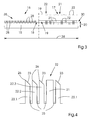
- FIG 3 shows a plan view of a first embodiment variant of the perforating tool proposed according to the invention in the form of a perforating knife out closer.
- the perforating tool 15 shown in FIG. 3 can be shown with a broken line Divide the imaginary center line into two halves 16 and 17 respectively.
- the formation of the first half 16 of the perforating tool 15 is uniform Sequence, the fold back marked punctiform perforation teeth 28 in this area, arranged in continuous repetition 35 along the length of the first half 16 are. Those that act on the fold back of a multilayer copy at certain points Perforating teeth 28 make 1 openings in the fold back through which openings in the fold back trapped air, which bulges the back, can escape, so that at allows multilayer copies to be formed with an air-free fold back.
- the continuous succession of perforating teeth 35 in the first half 16 of the perforating tool 15 is followed by a tool-free area 18.
- the tool-free area 18 enables the formation of a in the middle of a multilayer fold copy Material bridge.
- the material bridge which varies according to the selected depth of the tool-free Gaps 18 on the first half 16 of the perforating tool 15, stabilized the fold back of the multi-ply copy in the area of the middle.
- a cutting zone 19 is formed in the second half 17 of the perforating tool 15 proposed according to the invention.
- the cutting zone 19 immediately adjoins the tool-free gap 18 in the first half 16 of the perforating tool 15 and runs up to a first group of 22 inclined perforating elements.
- By means of the cutting zone 19 is adjacent to that created by the tool-free gap 18 in the multi-layer copy Material bridge creates a partial cut in the fold back.
- a first group 22 adjoins the continuously extending cutting zone 19 slanted perforation elements. Behind the first group 22 inclined perforating elements, preferably as perforating tongues separated from one another by longitudinal slots are formed, a straight section 21 follows, which acts as a cutting knife is trained. Cutting knife areas 21 and groups 22 of inclined perforating elements are in the second half 17 of the perforating tool configured according to the invention 15 added in alternating order.
- the configured according to the invention Perforating knife extends over a width 38 which is preferably the maximum processable Material web format corresponds.
- the side view of the perforating tool 15 configured according to the invention is a top view of both the straight cutting edges 21 and in an alternating order between these arranged groups 22 inclined Perforating elements, which are preferably designed as perforating tongues. From the dashed shown center line to the first group 22 extends an elongated Cutting zone 19.
- the height of the perforating tool 15 as shown Fig. 3 is identified by reference numeral 20, wherein the perforating tool 15 on Shell surfaces of perforating cylinders, for example, in material webs Folders can be added interchangeably. So perforating tools, which are subject to high wear and tear, can be replaced very quickly and easily with new ones that the perforations on multilayer material webs in the required quality and accuracy can be trained.
- the top view of a group 22 of perforating elements shown on an enlarged scale in FIG. 4 - preferably perforating tongues - comprises a first perforating tongue 22.1, a second perforating tongue 22.2 and a third perforating tongue 22.3.
- the individual perforation tongues are separated from each other by longitudinal slots 25, which are derived from the can serve during the perforation of paper dust, so that it is free of deposits can be derived from the perforation area.
- At the three perforation tongues 22.1, 22.2, 22.3 also closes a straight line separated by a longitudinal slot 25 Section 21, the upper edge of which is formed as a straight cutting edge is.
- Perforating elements with three perforating tongues can be within a group 22 of Perforating tongues on the second half 17 of the perforating tool 15 also per group 22 only two or more, i.e. four or five individual ones from each other through longitudinal slots 25 separate perforation tongues.
- the perforating tongues run out in a tip 26, which is part of an inclined surface 23 is.
- the thicker the too folding or to be perforated material webs, i.e. the more layers that were on the fold back is to be perforated the longer the incisions according to the Form perforation pattern 13 in one half of the fold back on the copy.
- the incision length depends on the immersion depth of the inclined surfaces 23 of the perforating tongues 22.1, 22.2, 22.3 of the perforating tool configured according to the invention in the second half 17 15 together in the multi-layer material web.
- the groups comprise 22 inclined perforating elements only two perforating tongues 22.1 and 22.2.
- the individual perforation tongues 22.1 and 22.2 are separated from each other by longitudinal slots 25 and about an axis of rotation 31, which with the Reference line 37 on the perforating tool 15 coincides, evenly, i.e. at the front edge 22.5 and at the rear edge 22.4 by the inclination angle 24 from the plane of the perforating tool 15 issued.
- the skew angle 24 around which the perforating tongues issued from the level of the perforating tool 15 is preferably in the range between 20 ° and 40 °.
- the inclination angle 24 is particularly preferably 30 °, the inclined position with the front edge of the perforating tongues 22.1 and 22.2 towards the center of the copy 1 to be folded is selected.
- FIG. 5.2 An alternative design option results from the embodiment variant according to FIG. 5.2 the second half 17 of the perforating tool 15.
- this variant are the adjoining the extended cutting section 19 Groups 22 inclined perforating tongues 22.1, 22.2 with their rear edge 22.4 issued from the plane of the perforating tool 15, while the leading edge 22.5 is straight is still in the plane of the perforating tool.
- this exhibition scheme is also from an off-center offset 33 of the preferably designed as perforating tongues, inclined perforating tongue 22.1 or 22.2 from the plane of the perforating tool 15 spoken.
- Reference number 24 denotes the exhibition angle, which in particularly preferred embodiment of a perforating tool is 30 °.
- 5.3 shows a further embodiment variant of the arrangement of groups 22 of inclined perforating elements within the second half 17 of a perforating tool 15 configured according to the invention.
- FIG. 5.4 shows a further possible embodiment of the second one Half 17 of a perforating tool 15 out.
- This variant is this characterized that in the second half 17 of the perforating tool according to herringbone a variety of 22.1, 22.2 to 22.n individual, inclined perforating tongues are trained.
- the individual perforated tongues arranged in a symmetrical exhibition 32 are interrupted by free spaces 36.
- the perforation tongues 22.1 to 22.n are each about its axis 31 at both the front and rear edges with respect to the reference line 37 of the perforating tool 15 deflected.
- All Perforating tongues arranged in a continuous repetition are at an angle 24 deflected from the perforating tool plane with respect to the reference line 37.
- the deflection angle is preferably in the range between 20 ° and 40 °, with particular preference a deflection angle of 30 ° is selected.
- 5.1, 5.2, 5.3 and 5.4 can be on one half of a Falzrükkens depending on a fold copy made up of several layers on strength, i.e. bring in the number of layers of the specimen, which is a shear stress compensation allow the inner copy layers relative to the outer copy layers, so that the fold back 4 can be made flatter overall and the side Offset 10 of the individual layers to one another an open end of the multilayer fold copy 1 can be significantly reduced.
Landscapes
- Folding Of Thin Sheet-Like Materials, Special Discharging Devices, And Others (AREA)
- Treatment Of Fiber Materials (AREA)
- Perforating, Stamping-Out Or Severing By Means Other Than Cutting (AREA)
- Registering, Tensioning, Guiding Webs, And Rollers Therefor (AREA)
- Preliminary Treatment Of Fibers (AREA)
Abstract
Description
- Fig. 1
- den sich beim Falzen von Exemplaren einstellenden Seitenversatz an den offenen Enden des Exemplars,
- Fig. 2
- die Draufsicht auf ein zu falzendes Exemplar, an dessen einer Hälfte die erfindungsgemäß aufzubringenden Einschnitte ausgebildet sind,
- Fig. 3
- eine Draufsicht auf eine Ausführungsvariante des erfindungsgemäß vorgeschlagenen Perforierwerkzeuges,
- Fig. 4
- eine Gruppe schräggestellter Perforierelemente in vergrößerter Darstellung und
- Fig. 5.1 - 5.4
- weitere Ausführungsvarianten einer Hälfte des erfindungsgemäß vorgeschlagenen Perforiermessers.
- 1
- Exemplar
- 2
- Bezugslinie
- 3
- geschlossenes Ende
- 4
- Falzrücken
- 5
- offenes Ende
- 6
- obere offene Seite
- 7
- untere offene Seite
- 8
- äußere Krümmung
- 9
- innere Krümmung
- 10
- Verschiebung
- 11
- ungefalzte Exemplarfläche
- 12
- Falzkante
- 13
- Perforationsmuster
- 14
- Verschiebungsrichtung
- 15
- Perforierwerkzeug
- 16
- erste Hälfte
- 17
- zweite Hälfte
- 18
- werkzeuglose Lücke
- 19
- Schneidzone
- 20
- Höhenerstreckung
- 21
- Schneidabschnitt
- 22
- Gruppe von Perforierelementen
- 22.1
- erste Perforierzunge
- 22.2
- zweite Perforierzunge
- 22.3
- dritte Perforierzunge
- 22.4
- Hinterkante
- 22.5
- Vorderkante
- 23
- geneigte Fläche
- 24
- Schrägstellungswinkel
- 25
- schlitzförmige Öffnung
- 26
- Perforierzungenspitze
- 27
- -
- 28
- durchgehende Perforierzähne
- 29
- Mittellinie
- 30
- Freiraum
- 31
- Drehachse
- 32
- symmetrische Ausstellung
- 33
- außenmittige Ausstellung
- 34
- außenmittige Ausstellung Vorderkante
- 35
- kontinuierliche Wiederholung
- 36
- Freiraum
- 37
- Bezugslinie
- 38
- Breite Perforierwerkzeug
Claims (14)
- Perforierwerkzeug zum Perforieren von ein- oder mehrlagigen Materialbahnen oder davon abgetrennten Exemplaren (1), wobei das Perforierwerkzeug eine erste Hälfte (16) und eine zweite Hälfte (17) umfaßt, mit nachfolgenden Merkmalen:1.1 einer in der ersten Hälfte (16) des Perforierwerkzeugs aufgenommenen Anzahl von Perforierzähnen (15)1.2 eine in der ersten Hälfte (16) ausgebildeten werkzeugfreien Lücke (18)1.3 einer in der zweiten Hälfte (17) angeordneten Schneidzone (19) und1.4 mindestens einer in der zweiten Hälfte (17) in alternierender Reihenfolge ausgebildeten Gruppe (22) von in bezug auf das Perforierwerkzeug (15) schräggestellter Perforierelemente (22.1, 22.2, 22.3).
- Perforierwerkzeug gemäß Anspruch 1, dadurch gekennzeichnet, daß die werkzeugfreie Lücke (18) der ersten Hälfte (16) an die Schneidzone (19) der zweiten Hälfte (17) angrenzt.
- Perforierwerkzeug gemäß Anspruch 1, dadurch gekennzeichnet, daß die Schneidzone (19) in der zweiten Hälfte (17) einerseits an die werkzeugfreie Lücke (18) und andererseits an die Gruppen (22) schräggestellter Perforierelemente (22.1, 22.2 und 22.3) angrenzt.
- Perforierwerkzeug gemäß Anspruch 1, dadurch gekennzeichnet, daß die Perforierelemente (22.1, 22.2, 22.3) der Gruppen (22) in Bezug auf das Perforierwerkzeug (15) um einen Winkel (24) zwischen 20° und 40° schräggestellt sind.
- Perforierwerkzeug gemäß Anspruch 4, dadurch gekennzeichnet, daß der Winkel (24) 30° beträgt.
- Perforierwerkzeug gemäß Anspruch 1, dadurch gekennzeichnet, daß die Gruppen (22) von Perforierelementen (22.1 bis 22.3) Schneidabschnitte (21) in alternierender Reihenfolge zwischen den Gruppen (22) enthalten.
- Perforierwerkzeug gemäß Anspruch 1, dadurch gekennzeichnet, daß die schräggestellten Perforierelemente (22.1, 22.2, 22.3) in bezug auf das Perforierwerkzeug (15) symmetrisch aus der Ebene des Perforierwerkzeuges (15) an Vorderkante (22.5) und Hinterkante (22.4) ausgestellt sind.
- Perforierwerkzeug gemäß Anspruch 1, dadurch gekennzeichnet, daß die schräggestellten Perforierelemente (22.1, 22.2, 22.3) in bezug auf das Perforierwerkzeug (15) einseitig mit ihrer Hinterkante (22.4) aus der Ebene des Perforierwerkzeuges (15) ausgestellt sind.
- Perforierwerkzeug gemäß Anspruch 1, dadurch gekennzeichnet, daß die schräggestellten Perforierelemente (22.1, 22.2, 22.3) in bezug auf die Ebene des Perforierwerkzeuges (15) mit ihrer Vorderkante (22.5) ausgestellt sind.
- Perforierwerkzeug gemäß Anspruch 1, dadurch gekennzeichnet, daß die schräggestellten Perforierelemente (22.1, 22.2, 22.3) als Perforierzungen ausgebildet sind.
- Perforierwerkzeug gemäß Anspruch 10, dadurch gekennzeichnet, daß die einzelnen Perforierelemente (22.1, 22.2, 22.3) einer Gruppe (22) von Perforierelementen durch schlitzförmige Öffnungen (25, 36) voneinander getrennt sind.
- Perforierwerkzeug gemäß Anspruch 1, dadurch gekennzeichnet, daß die schräggestellten Perforierelemente (22.1, 22.2, 22.3) der Gruppen (22) von Perforierelemente an ihrer Spitze (26) eine Schrägfläche (23) aufweisen.
- Perforiereinrichtung in einem einer bahnverarbeitenden Rotationsdruckmaschine nachgeordneten Falzapparat, mit einem Perforierwerkzeug nach einem der vorhergehenden Ansprüche.
- Perforierwerkzeug zum Perforieren von ein- oder mehrlagigen Materialbahnen oder davon abgetrennten Exemplaren (1), welches eine erste Hälfte (16) und eine zweite Hälfte (17) umfaßt, mit nachfolgenden Merkmalen:einer in der ersten Hälfte (16) des Perforierwerkzeugs aufgenommenen Anzahl von Perforierzähnen (15)eine in der ersten Hälfte (16) ausgebildeten werkzeugfreien Lücke (18)einer in der zweiten Hälfte (17) angeordneten Schneidzone (19) undeine Vielzahl von in der zweiten Hälfte (17) aneinander gereiht angeordneten und in bezug auf das Perforierwerkzeug (15) schräggestellten Perforierelementen (22.1, ....... 22.n).
Applications Claiming Priority (2)
| Application Number | Priority Date | Filing Date | Title |
|---|---|---|---|
| DE10059125A DE10059125A1 (de) | 2000-11-29 | 2000-11-29 | Einrichtung zur Perforation von Materialbahnen |
| DE10059125 | 2000-11-29 |
Publications (2)
| Publication Number | Publication Date |
|---|---|
| EP1211210A2 true EP1211210A2 (de) | 2002-06-05 |
| EP1211210A3 EP1211210A3 (de) | 2008-07-16 |
Family
ID=7665021
Family Applications (1)
| Application Number | Title | Priority Date | Filing Date |
|---|---|---|---|
| EP01126464A Withdrawn EP1211210A3 (de) | 2000-11-29 | 2001-11-09 | Einrichtung zur Perforation von Materialbahnen |
Country Status (6)
| Country | Link |
|---|---|
| US (1) | US20020121172A1 (de) |
| EP (1) | EP1211210A3 (de) |
| JP (1) | JP2002200861A (de) |
| CN (1) | CN1356201A (de) |
| DE (1) | DE10059125A1 (de) |
| HK (1) | HK1047722A1 (de) |
Families Citing this family (5)
| Publication number | Priority date | Publication date | Assignee | Title |
|---|---|---|---|---|
| US6991840B2 (en) * | 2003-12-10 | 2006-01-31 | Kimberly-Clark Worldwide, Inc. | Separably joined relationship between adjoining wipes |
| US20070084322A1 (en) * | 2005-10-19 | 2007-04-19 | Interwrap Inc. | Apparatus for cutting a line of perforation in a fabric |
| US20090155512A1 (en) * | 2007-12-13 | 2009-06-18 | Tsutama Satake Neto | Rolls of material providing one-handed dispensing of sheets of pre-determined length |
| DE102017112717A1 (de) * | 2017-06-09 | 2018-12-13 | Manroland Web Systems Gmbh | Perforiermesserleiste |
| DE102019117180A1 (de) * | 2019-06-26 | 2020-12-31 | Hauni Maschinenbau Gmbh | Vorrichtung und Verfahren zum Verbinden von zwei jeweils von einer Bobine ablaufenden Materialbahnen |
Family Cites Families (10)
| Publication number | Priority date | Publication date | Assignee | Title |
|---|---|---|---|---|
| US3228710A (en) * | 1965-05-18 | 1966-01-11 | Strachan & Henshaw Ltd | Folding of paper and like material |
| US3843113A (en) * | 1971-07-12 | 1974-10-22 | Harris Intertype Corp | Multi-page signatures and apparatus and method for producing same |
| DE3731117A1 (de) * | 1987-09-16 | 1989-03-30 | Koenig & Bauer Ag | Perforiermesser |
| FR2693403B1 (fr) * | 1992-07-10 | 1994-10-14 | Maury Imprimeur Sa | Cahier, destiné à la fabrication de brochures, livres et analogues; outil de perforation utile à sa préparation; procédé de préparation dudit cahier. |
| DE4428185A1 (de) * | 1994-08-09 | 1996-02-15 | Seyfert Wellpappe | Vorrichtung zum Herstellen von Aufreißperforationen |
| DE4431645A1 (de) * | 1994-09-06 | 1996-03-07 | Koenig & Bauer Albert Ag | Perforiermesser |
| US5524930A (en) * | 1994-09-09 | 1996-06-11 | Sure Perf, Inc. | Perforating blade and signature |
| DE4433602A1 (de) * | 1994-09-21 | 1996-03-28 | Koenig & Bauer Albert Ag | Gegenleiste für eine Perforiereinrichtung |
| DE29622954U1 (de) * | 1996-12-10 | 1997-09-25 | Drescher Geschäftsdrucke GmbH, 71277 Rutesheim | Endlospapier für die Fertigung von Papiererzeugnissen |
| EP1105333B1 (de) * | 1998-08-18 | 2002-06-19 | Heidelberger Druckmaschinen Aktiengesellschaft | Verfahren und vorrichtung zur perforation von materialbahnen |
-
2000
- 2000-11-29 DE DE10059125A patent/DE10059125A1/de not_active Withdrawn
-
2001
- 2001-11-09 EP EP01126464A patent/EP1211210A3/de not_active Withdrawn
- 2001-11-26 US US09/994,394 patent/US20020121172A1/en not_active Abandoned
- 2001-11-28 JP JP2001363160A patent/JP2002200861A/ja active Pending
- 2001-11-29 CN CN01134994A patent/CN1356201A/zh active Pending
-
2002
- 2002-12-31 HK HK02109460.0A patent/HK1047722A1/zh unknown
Also Published As
| Publication number | Publication date |
|---|---|
| EP1211210A3 (de) | 2008-07-16 |
| CN1356201A (zh) | 2002-07-03 |
| HK1047722A1 (zh) | 2003-03-07 |
| JP2002200861A (ja) | 2002-07-16 |
| DE10059125A1 (de) | 2002-06-06 |
| US20020121172A1 (en) | 2002-09-05 |
Similar Documents
| Publication | Publication Date | Title |
|---|---|---|
| EP0307891B1 (de) | Perforiermesser | |
| EP0701888B1 (de) | Perforiermesser | |
| EP0859733B1 (de) | Verfahren und vorrichtung zur herstellung von mehrlagigen zeitungsprodukten mit tabloidteil | |
| EP1105333B1 (de) | Verfahren und vorrichtung zur perforation von materialbahnen | |
| EP0814044A1 (de) | Verfahren zur Herstellung von mehrblättrigen Druckprodukten die aus gefalzten Bogen bestehen | |
| DE69524443T2 (de) | Messer zum perforieren und perforierter druckbogen | |
| EP1103508A2 (de) | Vorrichtung zum Falzen flächiger Exemplare | |
| DE102014205939B4 (de) | Verfahren und Vorrichtung zur Herstellung eines Druckproduktes | |
| DE10059125A1 (de) | Einrichtung zur Perforation von Materialbahnen | |
| DE2716999C2 (de) | Mehrschichtiger Durchschreibesatz | |
| CH627689A5 (de) | Endlossatz. | |
| DE102011011567A1 (de) | Zeitung | |
| EP0703047B1 (de) | Perforiereinrichtung | |
| DE102015202379B4 (de) | Verfahren zur Herstellung eines Druckproduktes | |
| EP1718463B1 (de) | Druckmaschine mit falztrichter | |
| DE10209213B4 (de) | Transportvorrichtung | |
| DE69905440T2 (de) | Beipackzettel aus Papier, Verpackung bestehend aus einem Etui mit einem solchen Beipackzettel, Anordnung bestehend aus der Verpackung und seinem Inhalt, Verfahren zur Herstellung des Beipackzettels | |
| DE102004005807B4 (de) | Falzapparat | |
| DE202009018120U1 (de) | Vorrichtung zur Verarbeitung von aus mehreren Papierlagen bestehenden Druckprodukten sowie Perforiermesser | |
| DE102015111286B4 (de) | Druckmaschine | |
| DE102011056612A1 (de) | Verfahren zur Bearbeitung von Druckbögen für Druckereiprodukte | |
| DE102019103027B4 (de) | Wellpappe mit Aufreißvorrichtung | |
| DE102016215373A1 (de) | Verfahren zur Herstellung eines Druckproduktes und Druckprodukt | |
| DE102015218209B4 (de) | Druckprodukt sowie Verfahen zur Herstellung eines Druckproduktes | |
| EP2567815B1 (de) | Druckprodukt und Rollendruckmaschine zum Herstellen des Druckprodukts |
Legal Events
| Date | Code | Title | Description |
|---|---|---|---|
| PUAI | Public reference made under article 153(3) epc to a published international application that has entered the european phase |
Free format text: ORIGINAL CODE: 0009012 |
|
| AK | Designated contracting states |
Kind code of ref document: A2 Designated state(s): AT BE CH CY DE DK ES FI FR GB GR IE IT LI LU MC NL PT SE TR |
|
| AX | Request for extension of the european patent |
Free format text: AL;LT;LV;MK;RO;SI |
|
| RAP1 | Party data changed (applicant data changed or rights of an application transferred) |
Owner name: HEIDELBERG WEB SYSTEMS, S.A. |
|
| RAP1 | Party data changed (applicant data changed or rights of an application transferred) |
Owner name: GOSS INTERNATIONAL MONTATAIRE S.A. |
|
| PUAL | Search report despatched |
Free format text: ORIGINAL CODE: 0009013 |
|
| AK | Designated contracting states |
Kind code of ref document: A3 Designated state(s): AT BE CH CY DE DK ES FI FR GB GR IE IT LI LU MC NL PT SE TR |
|
| AX | Request for extension of the european patent |
Extension state: AL LT LV MK RO SI |
|
| STAA | Information on the status of an ep patent application or granted ep patent |
Free format text: STATUS: THE APPLICATION IS DEEMED TO BE WITHDRAWN |
|
| 18D | Application deemed to be withdrawn |
Effective date: 20080603 |