EP1211148A1 - Dispositif de commande et antivol pour véhicule automobile comprenant ce dispositif de commande - Google Patents
Dispositif de commande et antivol pour véhicule automobile comprenant ce dispositif de commande Download PDFInfo
- Publication number
- EP1211148A1 EP1211148A1 EP01127924A EP01127924A EP1211148A1 EP 1211148 A1 EP1211148 A1 EP 1211148A1 EP 01127924 A EP01127924 A EP 01127924A EP 01127924 A EP01127924 A EP 01127924A EP 1211148 A1 EP1211148 A1 EP 1211148A1
- Authority
- EP
- European Patent Office
- Prior art keywords
- control
- control button
- male
- female
- ring
- Prior art date
- Legal status (The legal status is an assumption and is not a legal conclusion. Google has not performed a legal analysis and makes no representation as to the accuracy of the status listed.)
- Granted
Links
- 230000008878 coupling Effects 0.000 claims abstract description 49
- 238000010168 coupling process Methods 0.000 claims abstract description 49
- 238000005859 coupling reaction Methods 0.000 claims abstract description 49
- 230000000295 complement effect Effects 0.000 claims abstract description 22
- 230000005489 elastic deformation Effects 0.000 claims abstract description 7
- 230000002093 peripheral effect Effects 0.000 claims description 12
- 230000000694 effects Effects 0.000 claims description 8
- 230000003100 immobilizing effect Effects 0.000 claims description 7
- 210000000056 organ Anatomy 0.000 description 9
- 229910000639 Spring steel Inorganic materials 0.000 description 1
- 238000013475 authorization Methods 0.000 description 1
- 239000000463 material Substances 0.000 description 1
Images

Classifications
-
- B—PERFORMING OPERATIONS; TRANSPORTING
- B60—VEHICLES IN GENERAL
- B60R—VEHICLES, VEHICLE FITTINGS, OR VEHICLE PARTS, NOT OTHERWISE PROVIDED FOR
- B60R25/00—Fittings or systems for preventing or indicating unauthorised use or theft of vehicles
- B60R25/01—Fittings or systems for preventing or indicating unauthorised use or theft of vehicles operating on vehicle systems or fittings, e.g. on doors, seats or windscreens
- B60R25/04—Fittings or systems for preventing or indicating unauthorised use or theft of vehicles operating on vehicle systems or fittings, e.g. on doors, seats or windscreens operating on the propulsion system, e.g. engine or drive motor
-
- H—ELECTRICITY
- H01—ELECTRIC ELEMENTS
- H01H—ELECTRIC SWITCHES; RELAYS; SELECTORS; EMERGENCY PROTECTIVE DEVICES
- H01H3/00—Mechanisms for operating contacts
- H01H3/54—Mechanisms for coupling or uncoupling operating parts, driving mechanisms, or contacts
- H01H3/58—Mechanisms for coupling or uncoupling operating parts, driving mechanisms, or contacts using friction, toothed, or other mechanical clutch
-
- H—ELECTRICITY
- H01—ELECTRIC ELEMENTS
- H01H—ELECTRIC SWITCHES; RELAYS; SELECTORS; EMERGENCY PROTECTIVE DEVICES
- H01H3/00—Mechanisms for operating contacts
- H01H3/02—Operating parts, i.e. for operating driving mechanism by a mechanical force external to the switch
- H01H2003/0286—Operating parts, i.e. for operating driving mechanism by a mechanical force external to the switch having a weak point breaking or uncoupling on abnormal external force
Definitions
- the present invention relates to a control device and an anti-theft device for motor vehicle comprising this control device.
- a control device of the type comprising a control button, movable in rotation relative to a fixed support, coupled in rotation to a rod control substantially coaxial with the axis of rotation of the control button.
- An anti-theft device of this type generally comprises an electronic identification device consisting in particular of an electronic identifier, carried by a user of the vehicle authorized, and of an identification unit of this authorized user, on board the vehicle.
- the control button forms a manual control member for starting a vehicle engine and locking of a vehicle steering column.
- the control button is integral in rotation of the control rod, the latter being intended to actuate a multi-position switch. So the command button can be placed, together with the control rod, successively in a first position extreme rest angle, called the "STOP" position, an "ACCESSORIES” position, a “CONTACT” position and a second extreme angular position, opposite the first, so-called "START" position.
- the object of the invention is in particular to prevent an electronic anti-theft device from being damaged by forced rotation of the control button by a person not authorized, this by optimizing the inviolability of the lock.
- the subject of the invention is a control device of the aforementioned type, characterized in that the control button is coupled in rotation to the rod control using disengageable means under the effect of exceeding a torque predetermined relative between the control button and the control rod.
- Another subject of the invention is an anti-theft device for a motor vehicle, characterized in that it comprises a control device as defined above, the control button forming a manual control member for starting the engine of the vehicle and locking a vehicle steering column.
- control rod is intended to operate a multi-position switch, the angular position predetermined control button corresponding to an extreme angular position of this button called the "stop" position.
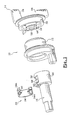
- FIGS. 1 and 2 show a control device according to the invention, designated by the general reference 10.
- the device 10 is intended to equip an electronic type anti-theft device for a motor vehicle.
- control device 10 comprises a support fixed 12, generally annular in shape, and a control button 14, movable in rotation relative to this fixed support 12.
- the control button 14 is coupled in rotation to a rod of control 16 substantially coaxial with the axis of rotation of this button 14.
- control button 14 forms a manual control of starting a vehicle engine and locking a steering column of this vehicle.
- the control rod 16 is intended to actuate a conventional switch with several positions (not shown).
- the control button 14 can be placed in a first extreme angular position of rest, called the “stop” position, a position “Accessories”, a “contact” position, and a second extreme angular position, opposite the first position, called the "start” position.
- the control button 14 is coupled to the control rod 16 using coupling means which will be described below.
- the coupling means comprise complementary male members 18 and female 20 of general cylindrical shapes substantially coaxial with the axis of rotation button 14.
- the male coupling member 18, integrally formed with the control button 14, is rotatably mounted in a bore 22 formed in the female member 20, coming from material with the control rod 16.
- the female coupling member 20 is rotatably mounted in a bore 24 formed in the fixed support 12.
- control button 14 has two fins 26, 28 of gripping and a skirt 30 partially surrounding the fixed support 12.
- the means for coupling the control button 14 and the rod control 16 also include means for locking the male members 18 and female 20 releasable by elastic deformation so that these coupling means are disengageable under the effect of exceeding a predetermined relative torque between the button 14 and rod 16.
- the keying means 32 preferably comprise a ring elastic 34 of open contour, for example made of spring steel. This ring 34, at least partially surrounding the female coupling member 20, is housed in a peripheral clearance 36 of this female member 20.
- a flat 38 is intended to cooperate with a first flat complementary end 34A of the ring to immobilize the latter in rotation relative to the female coupling member 20.
- a radial tongue 40 integral with the first end 34A of the ring, is intended to be fitted into a complementary transverse slot 42, formed in the peripheral flat 38, to immobilize longitudinally in translation the ring 34 relative to the female coupling member 20.
- the tongue 40 crossing the slot 42, also cooperates by fitting with a peripheral annular groove 43 of the male member 18 for axially immobilizing the male 18 and female coupling members 20 between them.
- the tongue 40 and groove 43 make it possible to immobilize the axially control button 14 relative to the control rod 16 while allowing the rotation of this button 14.
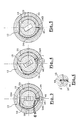
- the ring 34 includes a second end 34B, bent radially towards the inside of this ring 34, forming a key intended to be fitted into keyholes 44, 46, substantially radially aligned, formed in the male 18 and female 20 organs (see Figures 3 to 6).
- the key 34B is radially displaceable by elastic deformation of the ring 34 between a nesting position in the keying hole 44 of the member male coupling 18 (see FIG. 3) and a position for disengaging this hole 44 (see figure 5).
- the keying hole 44 of the male coupling member 18 is delimited by a ramp R (see Figure 6) urging the key 34B towards its position dislocation under the effect of exceeding the predetermined relative torque between the button 14 and the control rod 16.
- the bore 24 of the fixed support 12, in which the female coupling member 20 is mounted rotary has an internal clearance 48 for authorizing the disengagement of the key 34B in a predetermined angular position of the control button 14 relative to this fixed support 12.
- This predetermined angular position corresponds to the "stop" position button 14.
- the anti-theft device comprises a conventional electronic device identification, not shown, consisting in particular of an electronic identifier, intended to be worn by an authorized vehicle user, and an identification unit for this authorized user, on board the vehicle.
- the electronic identifier consists, for example, of a badge.
- the electronic identification device also comprises a key 50 forming an emergency identifier in the event of a badge failure. Information is likely to be exchanged between the key 50 and the identification unit using conventional means to transponder arranged in this key 50 and the anti-theft device.
- the emergency key 50 is intended to be housed in aligned holes 52,54 formed in the button control 14 and the control rod 16.
- the anti-theft device also comprises conventional means for locking in rotation. of the control rod 16 (not shown) intended to prevent the rotation of this rod 16 until an authorized user is identified.
- control button 14 is in the “stop” position illustrated in FIG. 3.
- the emergency key 50 is possibly housed in the button. control 14 and the control rod 16.
- the key 34B is fitted into the keyholes 44,46, so that the male 18 and female 20 coupling members are integral in rotation with one another.
- control button 14 which is driven in rotation, together with the control rod 16, as shown in the figure 4.
- the key 34B is connected to the rest of the ring 34 by a joining part J intended to cooperate, when the button 14 is not in its "stop" position, with the surface delimiting bore 24 of the fixed support 12 to prevent disengagement of the key 34B from the keying hole 44 formed in the male organ 18.
- This torque has the effect, when it exceeds a predetermined value which is function of the elasticity of the ring 34, to disengage the key 34B from the keyhole 44 by cooperation of the ramp R with this key 34B.
- the button control can be automatically coupled to the control rod again returning this button to its "stop" position.
Landscapes
- Engineering & Computer Science (AREA)
- Mechanical Engineering (AREA)
- Lock And Its Accessories (AREA)
Abstract
Description
- les moyens de couplage sont débrayables uniquement lorsque le bouton de commande est dans une position angulaire prédéterminée par rapport au support fixe ;
- les moyens de couplage comprennent :
- des organes complémentaires mâle et femelle, portés par le bouton de commande et la tige de commande, ces organes de couplage ayant des formes générales cylindriques sensiblement coaxiales à l'axe de rotation du bouton de commande, et
- des moyens de clavetage des organes mâle et femelle libérables par déformation élastique ;
- les moyens de clavetage comprennent une bague élastique de contour ouvert, entourant au moins partiellement l'organe de couplage femelle, comprenant une extrémité recourbée radialement vers l'intérieur de la bague formant une clavette destinée à être emboítée dans des trous de clavetage, sensiblement alignés radialement, ménagés dans les organes mâle et femelle, la clavette étant déplaçable radialement par déformation élastique de la bague entre une position d'emboítement dans le trou de clavetage de l'organe de couplage mâle et une position de déboítement de ce trou de clavetage de l'organe de couplage mâle ;
- le trou de clavetage de l'organe de couplage mâle est délimité par une rampe sollicitant la clavette vers sa position de déboítement sous l'effet du dépassement du couple relatif prédéterminé entre le bouton de commande et la tige de commande ;
- les organes de couplage mâle et femelle comprennent des moyens complémentaires d'immobilisation axiale entre eux ;
- l'organe de couplage femelle et la bague comprennent des moyens complémentaires d'immobilisation en rotation entre eux et des moyens complémentaires d'immobilisation en translation entre eux ;
- la bague est logée dans un dégagement périphérique de l'organe de couplage femelle, les moyens complémentaires d'immobilisation en rotation comprenant un méplat, délimitant au moins partiellement ce dégagement périphérique, destiné à coopérer avec une partie plane complémentaire de la bague ;
- les moyens complémentaires d'immobilisation en translation comprennent une languette radiale, solidaire de la partie plane de la bague, destinée à être emboítée dans une fente transversale complémentaire ménagée dans le méplat périphérique de l'organe de couplage femelle ;
- les moyens complémentaires d'immobilisation axiale des organes de couplage mâle et femelle comprennent une rainure annulaire périphérique ménagée dans l'organe mâle destinée à coopérer par emboítement avec la languette traversant la fente ;
- l'organe de couplage femelle est monté rotatif dans un alésage du support fixe comportant un dégagement interne d'autorisation du déboítement de la clavette dans la position angulaire prédéterminée du bouton de commande par rapport au support fixe ;
- la clavette est reliée au reste de la bague par une partie de jonction destinée à coopérer, lorsque le bouton de commande n'est pas dans sa position angulaire prédéterminée, avec la surface délimitant l'alésage du support fixe pour interdire le déboítement de la clavette du trou de clavetage ménagé dans l'organe de couplage mâle.
- la figure 1 est une vue en perspective éclatée d'un dispositif de commande selon l'invention;
- la figure 2 est une vue en coupe axiale du dispositif de commande représenté sur la figure 1 ;
- les figures 3 à 5 sont des vues en coupe suivant la ligne 3-3 de la figure 2, montrant les moyens de couplage des bouton et tige de commande dans différentes configurations d'utilisation ;
- la figure 6 est une vue de détail de la partie cerclée 6 de la figure 3.
Claims (13)
- Dispositif de commande du type comprenant un bouton de commande (14), déplaçable en rotation par rapport à un support fixe (12), couplé en rotation à une tige de commande (16) sensiblement coaxiale à l'axe de rotation du bouton de commande (14) à l'aide de moyens de couplage (18, 20, 32) débrayables sous l'effet du dépassement d'un couple relatif prédéterminé entre le bouton de commande (14) et la tige de commande (16), caractérisé en ce que les moyens de couplage comprennent :des organes complémentaires mâle (18) et femelle (20), portés par le bouton de commande (14) et la tige de commande (16), ces organes de couplage (18, 20) ayant des formes générales cylindriques sensiblement coaxiales à l'axe de rotation du bouton de commande (14), etdes moyens (32) de clavetage radial des organes mâle (18) et femelle (20) libérables radialement par déformation élastique.
- Dispositif selon la revendication 1, caractérisé en ce que les moyens de couplage (18, 20, 32) sont débrayables uniquement lorsque le bouton de commande (14) est dans une position angulaire prédéterminée par rapport au support fixe (12).
- Dispositif selon la revendication 1 ou 2, caractérisé en ce que les organes de couplage mâle (18) et femelle (20) comprennent des moyens complémentaires (40, 43) d'immobilisation axiale entre eux.
- Dispositif selon l'une quelconque des revendications 1 à 3, caractérisé en ce que les moyens de clavetage (32) comprennent une bague élastique (34) de contour ouvert, entourant au moins partiellement l'organe de couplage femelle (20), comprenant une extrémité recourbée radialement vers l'intérieur de la bague (34) formant une clavette (34B) destinée à être emboítée dans des trous de clavetage (44, 46), sensiblement alignés radialement, ménagés dans les organes mâle (18) et femelle (20), la clavette (34B) étant déplaçable radialement par déformation élastique de la bague (34) entre une position d'emboítement dans le trou de clavetage (44) de l'organe de couplage mâle (18) et une position de déboítement de ce trou de clavetage (44) de l'organe de couplage mâle (18).
- Dispositif selon la revendication 4, caractérisé en ce que le trou de clavetage (44) de l'organe de couplage mâle (18) est délimité par une rampe (R) sollicitant la clavette (34B) vers sa position de déboítement sous l'effet du dépassement du couple relatif prédéterminé entre le bouton de commande (14) et la tige de commande (16).
- Dispositif selon la revendication 4 ou 5, caractérisé en ce que l'organe de couplage femelle (20) et la bague (34) comprennent des moyens complémentaires (38, 34A) d'immobilisation en rotation entre eux et des moyens complémentaires (42, 40) d'immobilisation en translation entre eux.
- Dispositif selon la revendication 6, caractérisé en ce que la bague (34) est logée dans un dégagement périphérique (36) de l'organe de couplage femelle (20), les moyens complémentaires d'immobilisation en rotation comprenant un méplat (38), délimitant au moins partiellement ce dégagement périphérique (36), destiné à coopérer avec une partie plane complémentaire (34A) de la bague (34).
- Dispositif selon les revendications 6 et 7 prises ensemble, caractérisé en ce que les moyens complémentaires d'immobilisation en translation comprennent une languette radiale (40), solidaire de la partie plane de la bague (34), destinée à être emboítée dans une fente transversale complémentaire (42) ménagée dans le méplat périphérique (38) de l'organe de couplage femelle (20).
- Dispositif selon la revendication 3 prise en combinaison avec la revendication 8, caractérisé en ce que les moyens complémentaires d'immobilisation axiale des organes de couplage mâle (18) et femelle (20) comprennent une rainure annulaire périphérique (43) ménagée dans l'organe mâle (18) destinée à coopérer par emboítement avec la languette (40) traversant la fente (42).
- Dispositif selon la revendication 2 prise en combinaison avec l'une quelconque des revendications 3 à 9, caractérisé en ce que l'organe de couplage femelle (20) est monté rotatif dans un alésage (24) du support fixe (12) comportant un dégagement interne (48) d'autorisation du déboítement de la clavette (34B) dans la position angulaire prédéterminée du bouton de commande (14) par rapport au support fixe (12).
- Dispositif selon l'une quelconque des revendications 4 à 9 prise en combinaison avec la revendication 10, caractérisé en ce que la clavette (34B) est reliée au reste de la bague (34) par une partie de jonction (J) destinée à coopérer, lorsque le bouton de commande (14) n'est pas dans sa position angulaire prédéterminée, avec la surface délimitant l'alésage (24) du support fixe (12) pour interdire le déboítement de la clavette (34B) du trou de clavetage (44) ménagé dans l'organe de couplage mâle (18).
- Antivol pour véhicule automobile, caractérisé en ce qu'il comprend un dispositif de commande selon l'une quelconque des revendications 1 à 11, le bouton de commande (14) formant un organe de commande manuelle du démarrage d'un moteur du véhicule et du verrouillage d'une colonne de direction du véhicule.
- Antivol selon la revendication 12 comprenant un dispositif de commande selon la revendication 2, caractérisé en ce que la tige de commande (16) est destinée à actionner un commutateur à plusieurs positions, la position angulaire prédéterminée du bouton de commande (14) correspondant à une position angulaire extrême de ce bouton appelée position « stop ».
Applications Claiming Priority (2)
| Application Number | Priority Date | Filing Date | Title |
|---|---|---|---|
| FR0015436A FR2817214B1 (fr) | 2000-11-29 | 2000-11-29 | Dispositif de commande et antivol pour vehicule automobile comprenant ce dispositif de commande |
| FR0015436 | 2000-11-29 |
Publications (2)
| Publication Number | Publication Date |
|---|---|
| EP1211148A1 true EP1211148A1 (fr) | 2002-06-05 |
| EP1211148B1 EP1211148B1 (fr) | 2004-04-14 |
Family
ID=8857021
Family Applications (1)
| Application Number | Title | Priority Date | Filing Date |
|---|---|---|---|
| EP20010127924 Expired - Lifetime EP1211148B1 (fr) | 2000-11-29 | 2001-11-23 | Dispositif de commande et antivol pour véhicule automobile comprenant ce dispositif de commande |
Country Status (4)
| Country | Link |
|---|---|
| EP (1) | EP1211148B1 (fr) |
| DE (1) | DE60102780T2 (fr) |
| ES (1) | ES2219474T3 (fr) |
| FR (1) | FR2817214B1 (fr) |
Cited By (1)
| Publication number | Priority date | Publication date | Assignee | Title |
|---|---|---|---|---|
| EP1445158A3 (fr) * | 2003-02-06 | 2005-02-09 | Kabushiki Kaisha Tokai Rika Denki Seisakusho | Interrupteur-démarreur d'un moteur |
Citations (4)
| Publication number | Priority date | Publication date | Assignee | Title |
|---|---|---|---|---|
| DE4016779A1 (de) * | 1990-05-25 | 1991-11-28 | Huelsbeck & Fuerst | Lenkschloss fuer kraftfahrzeuge |
| DE4307339A1 (de) * | 1993-03-09 | 1994-09-15 | Huelsbeck & Fuerst | Lenkschloß für Fahrzeuge |
| EP0768220A1 (fr) * | 1995-10-09 | 1997-04-16 | Valeo Deutschland GmbH & Co. Sicherheitssysteme | Verrou de direction pour véhicule à moteur |
| WO1999014085A1 (fr) | 1997-09-12 | 1999-03-25 | Robert Bosch Gmbh | Systeme de serrure pour vehicule |
-
2000
- 2000-11-29 FR FR0015436A patent/FR2817214B1/fr not_active Expired - Fee Related
-
2001
- 2001-11-23 DE DE2001602780 patent/DE60102780T2/de not_active Expired - Lifetime
- 2001-11-23 EP EP20010127924 patent/EP1211148B1/fr not_active Expired - Lifetime
- 2001-11-23 ES ES01127924T patent/ES2219474T3/es not_active Expired - Lifetime
Patent Citations (4)
| Publication number | Priority date | Publication date | Assignee | Title |
|---|---|---|---|---|
| DE4016779A1 (de) * | 1990-05-25 | 1991-11-28 | Huelsbeck & Fuerst | Lenkschloss fuer kraftfahrzeuge |
| DE4307339A1 (de) * | 1993-03-09 | 1994-09-15 | Huelsbeck & Fuerst | Lenkschloß für Fahrzeuge |
| EP0768220A1 (fr) * | 1995-10-09 | 1997-04-16 | Valeo Deutschland GmbH & Co. Sicherheitssysteme | Verrou de direction pour véhicule à moteur |
| WO1999014085A1 (fr) | 1997-09-12 | 1999-03-25 | Robert Bosch Gmbh | Systeme de serrure pour vehicule |
Cited By (2)
| Publication number | Priority date | Publication date | Assignee | Title |
|---|---|---|---|---|
| EP1445158A3 (fr) * | 2003-02-06 | 2005-02-09 | Kabushiki Kaisha Tokai Rika Denki Seisakusho | Interrupteur-démarreur d'un moteur |
| US7290416B2 (en) | 2003-02-06 | 2007-11-06 | Kabushiki Kaisha Tokai Rika Denki Seisakusho | Engine switch device |
Also Published As
| Publication number | Publication date |
|---|---|
| FR2817214A1 (fr) | 2002-05-31 |
| DE60102780D1 (de) | 2004-05-19 |
| ES2219474T3 (es) | 2004-12-01 |
| EP1211148B1 (fr) | 2004-04-14 |
| DE60102780T2 (de) | 2004-09-23 |
| FR2817214B1 (fr) | 2003-03-28 |
Similar Documents
| Publication | Publication Date | Title |
|---|---|---|
| EP0747554B1 (fr) | Verrou destiné notamment à la fixation d'un siège pour véhicule automobile sur un plancher de ce véhicule | |
| FR2763290A1 (fr) | Articulation perfectionnee pour siege, notamment pour vehicule automobile, et siege muni de cette articulation | |
| FR2619880A1 (fr) | Butee de debrayage, notamment pour vehicules automobiles | |
| EP1211148B1 (fr) | Dispositif de commande et antivol pour véhicule automobile comprenant ce dispositif de commande | |
| FR2645607A1 (fr) | Dispositif rapide d'accouplement d'arbres menant et mene et son application, notamment a une direction d'automobile | |
| FR2852347A1 (fr) | Serrure renforcee pour ouvrant de vehicule automobile | |
| EP1569828B1 (fr) | Antivol pour vehicule automobile notamment de type electronique | |
| FR2788478A1 (fr) | Antivol de direction de vehicule automobile | |
| EP1228932B1 (fr) | Antivol perfectionné pour véhicule automobile | |
| FR2667276A1 (fr) | Dispositif de commande pour embrayage, notamment pour vehicule automobile. | |
| EP0794337A1 (fr) | Attache rapide de type à baionnette | |
| FR2752779A1 (fr) | Dispositif perfectionne de commande d'une boite de vitesses pour vehicule automobile | |
| EP0820915A1 (fr) | Dispositif de fixation d'un moyeu de volant de direction de véhicule, sur une extrémité d'un arbre de direction | |
| FR2816267A3 (fr) | Dispositif de commande a cle et unite de commande de demarrage d'un moteur de vehicule automobile comprenant ce dispositif | |
| EP0731243B1 (fr) | Verrou à rotor débrayable et antivol de direction de véhicule automobile équipé d'un tel verrou | |
| FR2817816A1 (fr) | Dispositif de commande perfectionne et antivol pour vehicule automobile comprenant ce dispositif | |
| FR2818715A1 (fr) | Butee pour embrayage, notamment de vehicule automobile | |
| JPH02181071A (ja) | 自動二輪車のキック始動装置 | |
| FR2833674A1 (fr) | Dispositif de transmission entre un arbre primaire moteur et un arbre de sortie | |
| EP1502829B1 (fr) | Dispositif de commande et antivol électronique pour véhicule automobile muni de ce dispositif | |
| EP0688925A1 (fr) | Verrou rotatif comportant des moyens perfectionnés d'assemblage | |
| EP0849437B1 (fr) | Dispositif de commande d'une soupape de moteur de véhicule automobile | |
| FR2821907A1 (fr) | Dispositif de securite pour la protection d'un moteur d'essuie-glace | |
| EP0190970A2 (fr) | Butée de débrayage, notamment pour véhicule automobile | |
| FR2749231A1 (fr) | Siege perfectionne a configuration variable pour vehicule automobile |
Legal Events
| Date | Code | Title | Description |
|---|---|---|---|
| PUAI | Public reference made under article 153(3) epc to a published international application that has entered the european phase |
Free format text: ORIGINAL CODE: 0009012 |
|
| AK | Designated contracting states |
Kind code of ref document: A1 Designated state(s): AT BE CH CY DE DK ES FI FR GB GR IE IT LI LU MC NL PT SE TR |
|
| AX | Request for extension of the european patent |
Free format text: AL;LT;LV;MK;RO;SI |
|
| 17P | Request for examination filed |
Effective date: 20021205 |
|
| AKX | Designation fees paid |
Designated state(s): DE ES FR GB IT |
|
| GRAP | Despatch of communication of intention to grant a patent |
Free format text: ORIGINAL CODE: EPIDOSNIGR1 |
|
| RAP1 | Party data changed (applicant data changed or rights of an application transferred) |
Owner name: VALEO SECURITE HABITACLE S.A.S. |
|
| GRAS | Grant fee paid |
Free format text: ORIGINAL CODE: EPIDOSNIGR3 |
|
| GRAA | (expected) grant |
Free format text: ORIGINAL CODE: 0009210 |
|
| AK | Designated contracting states |
Kind code of ref document: B1 Designated state(s): DE ES FR GB IT |
|
| REG | Reference to a national code |
Ref country code: GB Ref legal event code: FG4D Free format text: NOT ENGLISH |
|
| GBT | Gb: translation of ep patent filed (gb section 77(6)(a)/1977) |
Effective date: 20040414 |
|
| REF | Corresponds to: |
Ref document number: 60102780 Country of ref document: DE Date of ref document: 20040519 Kind code of ref document: P |
|
| REG | Reference to a national code |
Ref country code: IE Ref legal event code: FG4D Free format text: FRENCH |
|
| REG | Reference to a national code |
Ref country code: IE Ref legal event code: FD4D Ref country code: ES Ref legal event code: FG2A Ref document number: 2219474 Country of ref document: ES Kind code of ref document: T3 |
|
| PLBE | No opposition filed within time limit |
Free format text: ORIGINAL CODE: 0009261 |
|
| STAA | Information on the status of an ep patent application or granted ep patent |
Free format text: STATUS: NO OPPOSITION FILED WITHIN TIME LIMIT |
|
| 26N | No opposition filed |
Effective date: 20050117 |
|
| PGFP | Annual fee paid to national office [announced via postgrant information from national office to epo] |
Ref country code: IT Payment date: 20121122 Year of fee payment: 12 Ref country code: ES Payment date: 20121123 Year of fee payment: 12 |
|
| PG25 | Lapsed in a contracting state [announced via postgrant information from national office to epo] |
Ref country code: IT Free format text: LAPSE BECAUSE OF NON-PAYMENT OF DUE FEES Effective date: 20131123 |
|
| REG | Reference to a national code |
Ref country code: FR Ref legal event code: TP Owner name: U-SHIN FRANCE SAS, FR Effective date: 20140901 Ref country code: FR Ref legal event code: CD Owner name: U-SHIN FRANCE SAS, FR Effective date: 20140901 |
|
| PGFP | Annual fee paid to national office [announced via postgrant information from national office to epo] |
Ref country code: GB Payment date: 20141118 Year of fee payment: 14 Ref country code: DE Payment date: 20141113 Year of fee payment: 14 |
|
| PGFP | Annual fee paid to national office [announced via postgrant information from national office to epo] |
Ref country code: FR Payment date: 20141201 Year of fee payment: 14 |
|
| REG | Reference to a national code |
Ref country code: ES Ref legal event code: FD2A Effective date: 20150327 |
|
| PG25 | Lapsed in a contracting state [announced via postgrant information from national office to epo] |
Ref country code: ES Free format text: LAPSE BECAUSE OF NON-PAYMENT OF DUE FEES Effective date: 20131124 |
|
| REG | Reference to a national code |
Ref country code: DE Ref legal event code: R082 Ref document number: 60102780 Country of ref document: DE Representative=s name: PRINZ & PARTNER MBB PATENTANWAELTE RECHTSANWAE, DE |
|
| REG | Reference to a national code |
Ref country code: DE Ref legal event code: R082 Ref document number: 60102780 Country of ref document: DE Representative=s name: PRINZ & PARTNER MBB PATENTANWAELTE RECHTSANWAE, DE Effective date: 20150515 Ref country code: DE Ref legal event code: R081 Ref document number: 60102780 Country of ref document: DE Owner name: U-SHIN FRANCE SAS, FR Free format text: FORMER OWNER: VALEO SECURITE HABITACLE S.A.S., CRETEIL, FR Effective date: 20150515 |
|
| REG | Reference to a national code |
Ref country code: DE Ref legal event code: R119 Ref document number: 60102780 Country of ref document: DE |
|
| GBPC | Gb: european patent ceased through non-payment of renewal fee |
Effective date: 20151123 |
|
| REG | Reference to a national code |
Ref country code: FR Ref legal event code: ST Effective date: 20160729 |
|
| PG25 | Lapsed in a contracting state [announced via postgrant information from national office to epo] |
Ref country code: DE Free format text: LAPSE BECAUSE OF NON-PAYMENT OF DUE FEES Effective date: 20160601 Ref country code: GB Free format text: LAPSE BECAUSE OF NON-PAYMENT OF DUE FEES Effective date: 20151123 |
|
| PG25 | Lapsed in a contracting state [announced via postgrant information from national office to epo] |
Ref country code: FR Free format text: LAPSE BECAUSE OF NON-PAYMENT OF DUE FEES Effective date: 20151130 |