EP1210520B1 - Pompe a entrainement magnetique - Google Patents
Pompe a entrainement magnetique Download PDFInfo
- Publication number
- EP1210520B1 EP1210520B1 EP00960799A EP00960799A EP1210520B1 EP 1210520 B1 EP1210520 B1 EP 1210520B1 EP 00960799 A EP00960799 A EP 00960799A EP 00960799 A EP00960799 A EP 00960799A EP 1210520 B1 EP1210520 B1 EP 1210520B1
- Authority
- EP
- European Patent Office
- Prior art keywords
- partition
- rotor
- magnets
- pump according
- pump
- Prior art date
- Legal status (The legal status is an assumption and is not a legal conclusion. Google has not performed a legal analysis and makes no representation as to the accuracy of the status listed.)
- Expired - Lifetime
Links
- 238000005192 partition Methods 0.000 claims abstract description 33
- 238000007789 sealing Methods 0.000 claims abstract description 11
- 239000000463 material Substances 0.000 claims description 13
- 239000007788 liquid Substances 0.000 claims description 10
- 230000008878 coupling Effects 0.000 claims description 6
- 238000010168 coupling process Methods 0.000 claims description 6
- 238000005859 coupling reaction Methods 0.000 claims description 6
- 239000010935 stainless steel Substances 0.000 claims description 3
- 229910001220 stainless steel Inorganic materials 0.000 claims description 3
- 239000000126 substance Substances 0.000 claims description 3
- 229910001092 metal group alloy Inorganic materials 0.000 claims description 2
- 238000000926 separation method Methods 0.000 claims description 2
- 230000000284 resting effect Effects 0.000 claims 1
- 239000000243 solution Substances 0.000 description 7
- 229910000831 Steel Inorganic materials 0.000 description 4
- 230000004907 flux Effects 0.000 description 4
- 239000010959 steel Substances 0.000 description 4
- 208000031968 Cadaver Diseases 0.000 description 3
- 240000008042 Zea mays Species 0.000 description 3
- 239000002184 metal Substances 0.000 description 3
- 125000006850 spacer group Chemical group 0.000 description 3
- OKTJSMMVPCPJKN-UHFFFAOYSA-N Carbon Chemical compound [C] OKTJSMMVPCPJKN-UHFFFAOYSA-N 0.000 description 2
- 239000004952 Polyamide Substances 0.000 description 2
- 230000003416 augmentation Effects 0.000 description 2
- 230000005540 biological transmission Effects 0.000 description 2
- 239000000470 constituent Substances 0.000 description 2
- 230000007547 defect Effects 0.000 description 2
- 229910002804 graphite Inorganic materials 0.000 description 2
- 239000010439 graphite Substances 0.000 description 2
- 238000012423 maintenance Methods 0.000 description 2
- 229920002647 polyamide Polymers 0.000 description 2
- 229920000515 polycarbonate Polymers 0.000 description 2
- 239000004417 polycarbonate Substances 0.000 description 2
- 230000000135 prohibitive effect Effects 0.000 description 2
- 229920002994 synthetic fiber Polymers 0.000 description 2
- 240000000018 Gnetum gnemon Species 0.000 description 1
- 235000008612 Gnetum gnemon Nutrition 0.000 description 1
- XUIMIQQOPSSXEZ-UHFFFAOYSA-N Silicon Chemical compound [Si] XUIMIQQOPSSXEZ-UHFFFAOYSA-N 0.000 description 1
- 241001080024 Telles Species 0.000 description 1
- 239000000919 ceramic Substances 0.000 description 1
- 239000002131 composite material Substances 0.000 description 1
- 238000001816 cooling Methods 0.000 description 1
- 238000009713 electroplating Methods 0.000 description 1
- 238000010438 heat treatment Methods 0.000 description 1
- 238000005461 lubrication Methods 0.000 description 1
- 239000011259 mixed solution Substances 0.000 description 1
- 238000000465 moulding Methods 0.000 description 1
- 230000002035 prolonged effect Effects 0.000 description 1
- 238000005086 pumping Methods 0.000 description 1
- HBMJWWWQQXIZIP-UHFFFAOYSA-N silicon carbide Chemical compound [Si+]#[C-] HBMJWWWQQXIZIP-UHFFFAOYSA-N 0.000 description 1
- 229910010271 silicon carbide Inorganic materials 0.000 description 1
Images

Classifications
-
- F—MECHANICAL ENGINEERING; LIGHTING; HEATING; WEAPONS; BLASTING
- F04—POSITIVE - DISPLACEMENT MACHINES FOR LIQUIDS; PUMPS FOR LIQUIDS OR ELASTIC FLUIDS
- F04D—NON-POSITIVE-DISPLACEMENT PUMPS
- F04D29/00—Details, component parts, or accessories
- F04D29/04—Shafts or bearings, or assemblies thereof
- F04D29/046—Bearings
- F04D29/047—Bearings hydrostatic; hydrodynamic
-
- F—MECHANICAL ENGINEERING; LIGHTING; HEATING; WEAPONS; BLASTING
- F04—POSITIVE - DISPLACEMENT MACHINES FOR LIQUIDS; PUMPS FOR LIQUIDS OR ELASTIC FLUIDS
- F04D—NON-POSITIVE-DISPLACEMENT PUMPS
- F04D13/00—Pumping installations or systems
- F04D13/02—Units comprising pumps and their driving means
- F04D13/021—Units comprising pumps and their driving means containing a coupling
- F04D13/024—Units comprising pumps and their driving means containing a coupling a magnetic coupling
- F04D13/025—Details of the can separating the pump and drive area
-
- F—MECHANICAL ENGINEERING; LIGHTING; HEATING; WEAPONS; BLASTING
- F04—POSITIVE - DISPLACEMENT MACHINES FOR LIQUIDS; PUMPS FOR LIQUIDS OR ELASTIC FLUIDS
- F04D—NON-POSITIVE-DISPLACEMENT PUMPS
- F04D29/00—Details, component parts, or accessories
- F04D29/04—Shafts or bearings, or assemblies thereof
- F04D29/043—Shafts
Definitions
- the sealing wall is particularly important when the pumped liquid corrosive character, which is frequently the case in chemistry or electroplating.
- the motor 1 is connected to the centrifugal wheel 2 by an axis 3 and a rigid coupling device 4.
- the wheel 2 rotates in the pump body 5 which communicates with the suction pipe 6 and the discharge pipe. pump body at the passage of the axis 3 is ensured by the friction seal 8.
- a second potential defect concerns the sealing itself which can not be guaranteed in a perfect way, because of the small surface defects that can be meet on the rubbing support faces, and the inevitable creation of a film liquid between these surfaces.
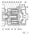
- FIG. 2 shows the motor 11, the wheel 12, the pump body 15, the suction pipes 16 and discharge 17.
- the sealing is here ensured by the continuous partition 18 assembled rigidly and hermetically between the body of pump 15 and the spacer 19 providing the connection with the motor flange 11.
- the drive rotor 20 On the axis of the motor 11 is rigidly mounted the drive rotor 20 in which is inserted, for example by overmoulding, a series of magnets 21.
- the driven rotor 22 integral with the wheel 12 is equipped with a series of magnets 23.
- the magnets 21, 23 are organized so that a north pole side drive is in face of a south pole driven side, and vice versa. We thus obtain a coupling magnetic field without mechanical contact, which must be sufficient to withstand without stalling the maximum torque absorbed by the wheel.
- Document FR-A-2311201 describes a pump with magnetic drive, in which the turbine is equipped with a magnetic core and is driven by the magnetic crown through a watertight bulkhead.
- the rotary turbine is supported by a fixed shaft, which is guided by a pair of bearings on the magnetic ring in connection with the motor shaft.
- the presence of bearings in addition to the output bearing of the motor shaft gives the whole a door to fake important, and additional embedding.
- the axial size of the pump is important, and the positioning of the turbine shaft does not allow to achieve perfect alignment.
- the axis of the motor is advantageously prolonged by a length sufficient for him allow to get into the heart of the driven rotor. It follows that the axis of the engine encompasses the axis of the wheel which, fixed, becomes turning. This is obviously not this rotation which is sought after, but the fact of having for the first rotor driven, a rigid support and perfectly aligned with the motor axis.
- the first driven rotor has a second ring which pivots on a first ring integral with the fixed partition.
- the bearing integrated in the partition comprises at least one self-lubricating ring constituting a thermal bridge for the evacuation of the calories generated by the trunnion of the first rotor driven to the radiator formed by the motor shaft.
- the sealing partition must not be interrupted, so it is necessary to complicate a little shape to make it bypass the extended tip, which belongs to the area external to the pumping circuit, whereas the axis 24 according to FIG. 2 of the prior art belonged to the inner zone.
- the partition will have to present a second cylindrical part coming to engage on the end of the axis motor, with the interposition of a friction sleeve, made for example in self-lubricating material.
- this axis now ensures the positioning of the rotor driven with precision and the rigidity wanted, this function does not have to be ensured by the partition sealing, which can be significantly lightened.
- this partition can be made in one piece, in a material chemically compatible with the pumped liquid.
- the part must be able to withstand the pressure of the liquid around the driven rotor, a sizeable pressure since it can be close to the discharge pressure of the pump. In cases where this pressure is high, and where there is no chemically compatible material having the sufficient mechanical strength, one can be reduced to a solution of composite partition with a mechanically strong outer shell, and a chemically compatible inner shell.
- the configuration described above has an obvious advantage, as far as it is appear a thermal bridge of strong section and thin thickness between the bearing driven rotor and the motor shaft.
- this advantage is mitigated by the it is necessary to evacuate in addition the calories produced by the rotation of the mouthpiece additional engine shaft in its own landing, but we're out there of reaching the pumped liquid, which makes it possible to use components classic mechanicals, whose performance is excellent.
- the sealing partition is shaped for chemical compatibility, while accuracy and mechanical strength are provided by an additional piece partially matching the shape of the partition, and made of a material having good mechanical strength.
- the room may be made of metal alloy, in particular steel stainless steel, and includes a ferrule inserted into the gap between the two series of magnets. The thickness of the ferrule is less than that of the envelope of the partition.
- a tip 42 extends the motor shaft 41, which it can be an integral part, or on which it can be assembled with rigidity and precision.
- the tip 42 is arranged to receive the fixing of the second drive rotor 30, this attachment being provided by any suitable mechanical means.
- the sealing partition consists of a casing 48 made of material chemically compatible with the pumped liquid, and a cylindrical shell 52 made of mechanically resistant material, especially stainless steel. This ferrule makes it possible to bring the resistance to the internal pressure, insofar as the constituent material of the envelope 48 may be insufficiently resistant.
- the envelope 48 is extended inwards by a sheath portion, in which axially introduces the tip 42.
- the ring 35 and the sleeve 53 may advantageously be overmoulded in the envelope of the partition 48 during the molding thereof.
- the sealing partition is therefore completely discharged from the centering function, and no longer has to be very rigid. On the contrary, it is desirable that it presents a minimum flexibility, so as not to upset the centering imposed by the tip 42.
- the device of FIG. evacuation to the outside of the calories generated by the rotation of the rotor wheel 32, the motor shaft 41 acting as a radiator via the nozzle 42.
- the calories pass successively through pieces 35, 48, 53, 54 and 54 'but all these transfers involve small thicknesses and large sections, which leads to a sufficiently efficient thermal bridge.
Landscapes
- Engineering & Computer Science (AREA)
- Mechanical Engineering (AREA)
- General Engineering & Computer Science (AREA)
- Physics & Mathematics (AREA)
- Fluid Mechanics (AREA)
- Structures Of Non-Positive Displacement Pumps (AREA)
- External Artificial Organs (AREA)
- Sealing Devices (AREA)
- Electromagnetic Pumps, Or The Like (AREA)
Applications Claiming Priority (3)
| Application Number | Priority Date | Filing Date | Title |
|---|---|---|---|
| FR9911242 | 1999-09-06 | ||
| FR9911242A FR2798169B1 (fr) | 1999-09-06 | 1999-09-06 | Pompe a entrainement magnetique |
| PCT/FR2000/002446 WO2001018401A1 (fr) | 1999-09-06 | 2000-09-06 | Pompe a entrainement magnetique |
Publications (2)
| Publication Number | Publication Date |
|---|---|
| EP1210520A1 EP1210520A1 (fr) | 2002-06-05 |
| EP1210520B1 true EP1210520B1 (fr) | 2003-11-19 |
Family
ID=9549645
Family Applications (1)
| Application Number | Title | Priority Date | Filing Date |
|---|---|---|---|
| EP00960799A Expired - Lifetime EP1210520B1 (fr) | 1999-09-06 | 2000-09-06 | Pompe a entrainement magnetique |
Country Status (8)
| Country | Link |
|---|---|
| US (1) | US6672818B1 (enExample) |
| EP (1) | EP1210520B1 (enExample) |
| JP (1) | JP2003508689A (enExample) |
| AT (1) | ATE254723T1 (enExample) |
| DE (1) | DE60006689T2 (enExample) |
| ES (1) | ES2211599T3 (enExample) |
| FR (1) | FR2798169B1 (enExample) |
| WO (1) | WO2001018401A1 (enExample) |
Families Citing this family (19)
| Publication number | Priority date | Publication date | Assignee | Title |
|---|---|---|---|---|
| AU2003247622A1 (en) * | 2002-06-27 | 2004-01-19 | Nitromed, Inc. | Cyclooxygenase-2 selective inhibitors, compositions and methods of use |
| US7131825B2 (en) * | 2004-01-30 | 2006-11-07 | Isothermal Systems Research, Inc. | Spindle-motor driven pump system |
| DE502005005690D1 (de) * | 2004-03-16 | 2008-11-27 | Emb Papst St Georgen Gmbh & Co | Anordnung mit einem elektronisch kommutierten aussenläufermotor |
| GB2418074A (en) * | 2004-09-14 | 2006-03-15 | Dana Automotive Ltd | A method of making a permanent magnet electric motor rotor |
| JP4297859B2 (ja) * | 2004-09-28 | 2009-07-15 | 三洋電機株式会社 | 電動車輪用ハブユニット及び該ハブユニットを具えた乗物 |
| DE502005006436D1 (de) * | 2004-10-06 | 2009-02-26 | Ebm Papst St Georgen Gmbh & Co | Anordnung zur förderung von fluiden |
| CN1828027B (zh) * | 2005-02-28 | 2011-10-19 | 台达电子工业股份有限公司 | 液冷式散热模块 |
| CN1983778B (zh) * | 2005-12-08 | 2011-01-26 | 刘素荣 | 液态金属磁力驱动无叶轮离心泵 |
| ITBS20060079A1 (it) * | 2006-03-30 | 2007-09-30 | Metelli S P A | Pompa a trascinamento magnetico perfezionata |
| US8575802B2 (en) * | 2010-02-03 | 2013-11-05 | Src Electrical Llc | Locomotive starter motor |
| DE102012024130B4 (de) * | 2012-12-11 | 2014-09-11 | Klaus Union Gmbh & Co. Kg | Spalttopf für magnetgekuppelte Pumpen sowie Herstellungsverfahren |
| FR3011895B1 (fr) * | 2013-10-14 | 2016-03-04 | Pompes Salmson Sa | Ensemble coussinet, support de coussinet pour une pompe de circulation |
| EP2899855B1 (de) * | 2014-01-23 | 2022-08-24 | Pierburg Pump Technology GmbH | Elektrische Kraftfahrzeug-Kühlmittelpumpe |
| US9771938B2 (en) | 2014-03-11 | 2017-09-26 | Peopleflo Manufacturing, Inc. | Rotary device having a radial magnetic coupling |
| US9920764B2 (en) | 2015-09-30 | 2018-03-20 | Peopleflo Manufacturing, Inc. | Pump devices |
| WO2018008896A1 (ko) * | 2016-07-04 | 2018-01-11 | 주식회사 아모텍 | 워터 펌프 |
| KR101968162B1 (ko) * | 2016-07-04 | 2019-04-11 | 주식회사 아모텍 | 워터 펌프 |
| US11193493B2 (en) | 2016-07-04 | 2021-12-07 | Amotech Co., Ltd. | Water pump |
| FR3074622B1 (fr) * | 2017-12-04 | 2021-07-30 | Ifp Energies Now | Dispositif de compression d'un fluide entraine par une machine electrique avec un arbre de rotor ayant une frette amagnetique |
Family Cites Families (11)
| Publication number | Priority date | Publication date | Assignee | Title |
|---|---|---|---|---|
| US3172364A (en) * | 1962-10-01 | 1965-03-09 | P G Products Mfg Co Inc | Pump |
| FR2311201A1 (fr) * | 1975-05-12 | 1976-12-10 | Siebec Filtres | Perfectionnement apporte aux pompes a entrainement magnetique |
| US4207485A (en) * | 1978-04-24 | 1980-06-10 | The Garrett Corporation | Magnetic coupling |
| US4645432A (en) * | 1986-02-14 | 1987-02-24 | General Motors Corporation | Magnetic drive vehicle coolant pump |
| JPH01125591A (ja) * | 1987-11-06 | 1989-05-18 | Sanyo Electric Co Ltd | マグネットポンプ |
| JPH0276191U (enExample) * | 1988-11-30 | 1990-06-11 | ||
| DE3927391A1 (de) * | 1989-08-19 | 1991-02-21 | Bosch Gmbh Robert | Vorrichtung zum beheizen des fahrgastraumes eines kraftfahrzeuges |
| JPH05252800A (ja) * | 1992-02-28 | 1993-09-28 | Fuji Oozx Kk | 渦電流継手を用いた動力伝達装置の制御方法及び装置 |
| FR2715442B1 (fr) * | 1994-01-26 | 1996-03-01 | Lorraine Carbone | Pompe centrifuge à entraînement magnétique. |
| US5833437A (en) * | 1996-07-02 | 1998-11-10 | Shurflo Pump Manufacturing Co. | Bilge pump |
| GB9717866D0 (en) * | 1997-08-23 | 1997-10-29 | Concentric Pumps Ltd | Improvements to rotary pumps |
-
1999
- 1999-09-06 FR FR9911242A patent/FR2798169B1/fr not_active Expired - Lifetime
-
2000
- 2000-09-06 EP EP00960799A patent/EP1210520B1/fr not_active Expired - Lifetime
- 2000-09-06 WO PCT/FR2000/002446 patent/WO2001018401A1/fr not_active Ceased
- 2000-09-06 JP JP2001521905A patent/JP2003508689A/ja not_active Ceased
- 2000-09-06 US US10/069,358 patent/US6672818B1/en not_active Expired - Fee Related
- 2000-09-06 DE DE60006689T patent/DE60006689T2/de not_active Expired - Lifetime
- 2000-09-06 ES ES00960799T patent/ES2211599T3/es not_active Expired - Lifetime
- 2000-09-06 AT AT00960799T patent/ATE254723T1/de not_active IP Right Cessation
Also Published As
| Publication number | Publication date |
|---|---|
| FR2798169A1 (fr) | 2001-03-09 |
| EP1210520A1 (fr) | 2002-06-05 |
| DE60006689D1 (de) | 2003-12-24 |
| WO2001018401A1 (fr) | 2001-03-15 |
| FR2798169B1 (fr) | 2001-11-16 |
| ES2211599T3 (es) | 2004-07-16 |
| JP2003508689A (ja) | 2003-03-04 |
| DE60006689T2 (de) | 2004-10-07 |
| ATE254723T1 (de) | 2003-12-15 |
| US6672818B1 (en) | 2004-01-06 |
Similar Documents
| Publication | Publication Date | Title |
|---|---|---|
| EP1210520B1 (fr) | Pompe a entrainement magnetique | |
| EP0882892B1 (fr) | Machine du type scroll | |
| EP0665378A1 (fr) | Pompe centrifuge à entraînement magnétique | |
| FR2608228A1 (fr) | Pompe a liquide, notamment pompe a eau, en particulier pour vehicules automobiles | |
| EP0494008A1 (fr) | Turbopompe à gavage intégré en flux axial | |
| EP0882893B1 (fr) | Machine a déplacement de fluide du type scroll | |
| FR3134435A1 (fr) | Pompe à vide | |
| FR3047776B1 (fr) | Turbomachine et son procede de montage | |
| FR2465353A1 (fr) | Moteur pas-a-pas miniature pour mouvement de montre | |
| BE1000978A5 (fr) | Motopompe integree a moteur electrique et pompe rotative. | |
| FR2864157A1 (fr) | Rotor de turbine monobloc et engrenage a pignons et technique de fabrication de ces derniers | |
| FR2890251A1 (fr) | Rotor de type cage. | |
| FR2701610A1 (fr) | Dispositif de pivotement pour rotor noyé. | |
| WO2020002817A1 (fr) | Machine tournante supraconductrice | |
| EP2469093B1 (fr) | Pompe de circulation de fluide et son utilisation | |
| EP0823027B1 (fr) | Pompe centrifuge a entrainement magnetique | |
| FR2831926A1 (fr) | Dispositif de pompage a pompe moineau | |
| WO2025132106A1 (fr) | Machine électrique tournante à flux axial | |
| WO2023099853A1 (fr) | Bras de servitude pour un carter d'échappement d'une turbomachine | |
| FR2497880A1 (fr) | Pompe a engrenages | |
| EP0291780A1 (fr) | Pompe à entraînement magnétique | |
| EP4348018A1 (fr) | Turbomachine équipée d'une pompe à entrainement magnétique | |
| FR3065496A1 (fr) | Motopompe a rotor noye | |
| FR3143910A1 (fr) | Machine électrique tournante à canal de refroidissement perfectionné | |
| FR2533976A1 (fr) | Motopompe a moteur elecrique a rotor noye |
Legal Events
| Date | Code | Title | Description |
|---|---|---|---|
| PUAI | Public reference made under article 153(3) epc to a published international application that has entered the european phase |
Free format text: ORIGINAL CODE: 0009012 |
|
| 17P | Request for examination filed |
Effective date: 20020226 |
|
| AK | Designated contracting states |
Kind code of ref document: A1 Designated state(s): AT BE CH CY DE DK ES FI FR GB GR IE IT LI LU MC NL PT SE |
|
| GRAH | Despatch of communication of intention to grant a patent |
Free format text: ORIGINAL CODE: EPIDOS IGRA |
|
| GRAH | Despatch of communication of intention to grant a patent |
Free format text: ORIGINAL CODE: EPIDOS IGRA |
|
| GRAA | (expected) grant |
Free format text: ORIGINAL CODE: 0009210 |
|
| AK | Designated contracting states |
Kind code of ref document: B1 Designated state(s): AT BE CH CY DE DK ES FI FR GB GR IE IT LI LU MC NL PT SE |
|
| PG25 | Lapsed in a contracting state [announced via postgrant information from national office to epo] |
Ref country code: CY Free format text: LAPSE BECAUSE OF FAILURE TO SUBMIT A TRANSLATION OF THE DESCRIPTION OR TO PAY THE FEE WITHIN THE PRESCRIBED TIME-LIMIT Effective date: 20031119 Ref country code: FI Free format text: LAPSE BECAUSE OF FAILURE TO SUBMIT A TRANSLATION OF THE DESCRIPTION OR TO PAY THE FEE WITHIN THE PRESCRIBED TIME-LIMIT Effective date: 20031119 Ref country code: AT Free format text: LAPSE BECAUSE OF FAILURE TO SUBMIT A TRANSLATION OF THE DESCRIPTION OR TO PAY THE FEE WITHIN THE PRESCRIBED TIME-LIMIT Effective date: 20031119 Ref country code: IE Free format text: LAPSE BECAUSE OF FAILURE TO SUBMIT A TRANSLATION OF THE DESCRIPTION OR TO PAY THE FEE WITHIN THE PRESCRIBED TIME-LIMIT Effective date: 20031119 Ref country code: NL Free format text: LAPSE BECAUSE OF FAILURE TO SUBMIT A TRANSLATION OF THE DESCRIPTION OR TO PAY THE FEE WITHIN THE PRESCRIBED TIME-LIMIT Effective date: 20031119 |
|
| REG | Reference to a national code |
Ref country code: GB Ref legal event code: FG4D Free format text: NOT ENGLISH |
|
| REG | Reference to a national code |
Ref country code: CH Ref legal event code: EP |
|
| REF | Corresponds to: |
Ref document number: 60006689 Country of ref document: DE Date of ref document: 20031224 Kind code of ref document: P |
|
| REG | Reference to a national code |
Ref country code: IE Ref legal event code: FG4D Free format text: FRENCH |
|
| PG25 | Lapsed in a contracting state [announced via postgrant information from national office to epo] |
Ref country code: GR Free format text: LAPSE BECAUSE OF FAILURE TO SUBMIT A TRANSLATION OF THE DESCRIPTION OR TO PAY THE FEE WITHIN THE PRESCRIBED TIME-LIMIT Effective date: 20040219 Ref country code: SE Free format text: LAPSE BECAUSE OF FAILURE TO SUBMIT A TRANSLATION OF THE DESCRIPTION OR TO PAY THE FEE WITHIN THE PRESCRIBED TIME-LIMIT Effective date: 20040219 Ref country code: DK Free format text: LAPSE BECAUSE OF FAILURE TO SUBMIT A TRANSLATION OF THE DESCRIPTION OR TO PAY THE FEE WITHIN THE PRESCRIBED TIME-LIMIT Effective date: 20040219 |
|
| GBT | Gb: translation of ep patent filed (gb section 77(6)(a)/1977) |
Effective date: 20040223 |
|
| NLV1 | Nl: lapsed or annulled due to failure to fulfill the requirements of art. 29p and 29m of the patents act | ||
| REG | Reference to a national code |
Ref country code: IE Ref legal event code: FD4D |
|
| REG | Reference to a national code |
Ref country code: ES Ref legal event code: FG2A Ref document number: 2211599 Country of ref document: ES Kind code of ref document: T3 |
|
| PG25 | Lapsed in a contracting state [announced via postgrant information from national office to epo] |
Ref country code: LU Free format text: LAPSE BECAUSE OF NON-PAYMENT OF DUE FEES Effective date: 20040906 |
|
| PLBE | No opposition filed within time limit |
Free format text: ORIGINAL CODE: 0009261 |
|
| STAA | Information on the status of an ep patent application or granted ep patent |
Free format text: STATUS: NO OPPOSITION FILED WITHIN TIME LIMIT |
|
| PG25 | Lapsed in a contracting state [announced via postgrant information from national office to epo] |
Ref country code: BE Free format text: LAPSE BECAUSE OF NON-PAYMENT OF DUE FEES Effective date: 20040930 Ref country code: MC Free format text: LAPSE BECAUSE OF NON-PAYMENT OF DUE FEES Effective date: 20040930 |
|
| 26N | No opposition filed |
Effective date: 20040820 |
|
| BERE | Be: lapsed |
Owner name: SOC. *SIEBEC Effective date: 20040930 |
|
| BERE | Be: lapsed |
Owner name: SOC. *SIEBEC Effective date: 20040930 |
|
| PG25 | Lapsed in a contracting state [announced via postgrant information from national office to epo] |
Ref country code: PT Free format text: LAPSE BECAUSE OF NON-PAYMENT OF DUE FEES Effective date: 20040419 |
|
| PGFP | Annual fee paid to national office [announced via postgrant information from national office to epo] |
Ref country code: GB Payment date: 20070905 Year of fee payment: 8 |
|
| REG | Reference to a national code |
Ref country code: FR Ref legal event code: TP |
|
| PGFP | Annual fee paid to national office [announced via postgrant information from national office to epo] |
Ref country code: IT Payment date: 20080926 Year of fee payment: 9 |
|
| PGFP | Annual fee paid to national office [announced via postgrant information from national office to epo] |
Ref country code: CH Payment date: 20081002 Year of fee payment: 9 |
|
| PGFP | Annual fee paid to national office [announced via postgrant information from national office to epo] |
Ref country code: ES Payment date: 20081021 Year of fee payment: 9 |
|
| GBPC | Gb: european patent ceased through non-payment of renewal fee |
Effective date: 20080906 |
|
| PG25 | Lapsed in a contracting state [announced via postgrant information from national office to epo] |
Ref country code: GB Free format text: LAPSE BECAUSE OF NON-PAYMENT OF DUE FEES Effective date: 20080906 |
|
| REG | Reference to a national code |
Ref country code: CH Ref legal event code: PL |
|
| PG25 | Lapsed in a contracting state [announced via postgrant information from national office to epo] |
Ref country code: LI Free format text: LAPSE BECAUSE OF NON-PAYMENT OF DUE FEES Effective date: 20090930 Ref country code: CH Free format text: LAPSE BECAUSE OF NON-PAYMENT OF DUE FEES Effective date: 20090930 |
|
| PG25 | Lapsed in a contracting state [announced via postgrant information from national office to epo] |
Ref country code: IT Free format text: LAPSE BECAUSE OF NON-PAYMENT OF DUE FEES Effective date: 20090906 |
|
| REG | Reference to a national code |
Ref country code: ES Ref legal event code: FD2A Effective date: 20110714 |
|
| PG25 | Lapsed in a contracting state [announced via postgrant information from national office to epo] |
Ref country code: ES Free format text: LAPSE BECAUSE OF NON-PAYMENT OF DUE FEES Effective date: 20110704 |
|
| PG25 | Lapsed in a contracting state [announced via postgrant information from national office to epo] |
Ref country code: ES Free format text: LAPSE BECAUSE OF NON-PAYMENT OF DUE FEES Effective date: 20090907 |
|
| REG | Reference to a national code |
Ref country code: DE Ref legal event code: R082 Ref document number: 60006689 Country of ref document: DE Representative=s name: PATRONUS IP PATENT- & RECHTSANWAELTE BERNHARD , DE |
|
| PGFP | Annual fee paid to national office [announced via postgrant information from national office to epo] |
Ref country code: DE Payment date: 20150908 Year of fee payment: 16 |
|
| REG | Reference to a national code |
Ref country code: FR Ref legal event code: PLFP Year of fee payment: 17 |
|
| REG | Reference to a national code |
Ref country code: DE Ref legal event code: R119 Ref document number: 60006689 Country of ref document: DE |
|
| PG25 | Lapsed in a contracting state [announced via postgrant information from national office to epo] |
Ref country code: DE Free format text: LAPSE BECAUSE OF NON-PAYMENT OF DUE FEES Effective date: 20170401 |
|
| REG | Reference to a national code |
Ref country code: FR Ref legal event code: PLFP Year of fee payment: 18 |
|
| REG | Reference to a national code |
Ref country code: FR Ref legal event code: PLFP Year of fee payment: 19 |
|
| PGFP | Annual fee paid to national office [announced via postgrant information from national office to epo] |
Ref country code: FR Payment date: 20190927 Year of fee payment: 20 |