EP1209399A2 - Tube polymère à nervure dotée d'au moins trois couches dont au moins deux de matériaux polymères différents - Google Patents
Tube polymère à nervure dotée d'au moins trois couches dont au moins deux de matériaux polymères différents Download PDFInfo
- Publication number
- EP1209399A2 EP1209399A2 EP02001200A EP02001200A EP1209399A2 EP 1209399 A2 EP1209399 A2 EP 1209399A2 EP 02001200 A EP02001200 A EP 02001200A EP 02001200 A EP02001200 A EP 02001200A EP 1209399 A2 EP1209399 A2 EP 1209399A2
- Authority
- EP
- European Patent Office
- Prior art keywords
- layer
- tubing
- region
- thermoplastic
- extrudable
- Prior art date
- Legal status (The legal status is an assumption and is not a legal conclusion. Google has not performed a legal analysis and makes no representation as to the accuracy of the status listed.)
- Withdrawn
Links
- 239000000463 material Substances 0.000 title claims description 75
- 229920001169 thermoplastic Polymers 0.000 claims abstract description 48
- 239000004416 thermosoftening plastic Substances 0.000 claims abstract description 48
- 239000012815 thermoplastic material Substances 0.000 claims abstract description 41
- 230000032798 delamination Effects 0.000 claims abstract description 8
- 229920002647 polyamide Polymers 0.000 claims description 56
- 239000004952 Polyamide Substances 0.000 claims description 55
- 229910052799 carbon Inorganic materials 0.000 claims description 44
- 239000000203 mixture Substances 0.000 claims description 32
- JIAARYAFYJHUJI-UHFFFAOYSA-L zinc dichloride Chemical compound [Cl-].[Cl-].[Zn+2] JIAARYAFYJHUJI-UHFFFAOYSA-L 0.000 claims description 26
- 239000004020 conductor Substances 0.000 claims description 22
- JHWNWJKBPDFINM-UHFFFAOYSA-N Laurolactam Chemical compound O=C1CCCCCCCCCCCN1 JHWNWJKBPDFINM-UHFFFAOYSA-N 0.000 claims description 21
- 229920000299 Nylon 12 Polymers 0.000 claims description 21
- OKTJSMMVPCPJKN-UHFFFAOYSA-N Carbon Chemical compound [C] OKTJSMMVPCPJKN-UHFFFAOYSA-N 0.000 claims description 19
- 229920002292 Nylon 6 Polymers 0.000 claims description 18
- 229930195733 hydrocarbon Natural products 0.000 claims description 16
- 150000002430 hydrocarbons Chemical class 0.000 claims description 16
- 239000012530 fluid Substances 0.000 claims description 14
- 229920002725 thermoplastic elastomer Polymers 0.000 claims description 14
- 235000005074 zinc chloride Nutrition 0.000 claims description 13
- 239000011592 zinc chloride Substances 0.000 claims description 13
- 229920000571 Nylon 11 Polymers 0.000 claims description 12
- PXHVJJICTQNCMI-UHFFFAOYSA-N Nickel Chemical compound [Ni] PXHVJJICTQNCMI-UHFFFAOYSA-N 0.000 claims description 10
- -1 polybutylene terephthalate Polymers 0.000 claims description 10
- 239000004215 Carbon black (E152) Substances 0.000 claims description 9
- 239000000178 monomer Substances 0.000 claims description 9
- 229920001577 copolymer Polymers 0.000 claims description 8
- JBKVHLHDHHXQEQ-UHFFFAOYSA-N epsilon-caprolactam Chemical compound O=C1CCCCCN1 JBKVHLHDHHXQEQ-UHFFFAOYSA-N 0.000 claims description 8
- VGGSQFUCUMXWEO-UHFFFAOYSA-N Ethene Chemical compound C=C VGGSQFUCUMXWEO-UHFFFAOYSA-N 0.000 claims description 7
- 239000005977 Ethylene Substances 0.000 claims description 7
- 229920001707 polybutylene terephthalate Polymers 0.000 claims description 6
- 238000006116 polymerization reaction Methods 0.000 claims description 6
- RYGMFSIKBFXOCR-UHFFFAOYSA-N Copper Chemical compound [Cu] RYGMFSIKBFXOCR-UHFFFAOYSA-N 0.000 claims description 5
- IMROMDMJAWUWLK-UHFFFAOYSA-N Ethenol Chemical compound OC=C IMROMDMJAWUWLK-UHFFFAOYSA-N 0.000 claims description 5
- XUIMIQQOPSSXEZ-UHFFFAOYSA-N Silicon Chemical compound [Si] XUIMIQQOPSSXEZ-UHFFFAOYSA-N 0.000 claims description 5
- BQCADISMDOOEFD-UHFFFAOYSA-N Silver Chemical compound [Ag] BQCADISMDOOEFD-UHFFFAOYSA-N 0.000 claims description 5
- 238000005452 bending Methods 0.000 claims description 5
- 229910052802 copper Inorganic materials 0.000 claims description 5
- 239000010949 copper Substances 0.000 claims description 5
- PCHJSUWPFVWCPO-UHFFFAOYSA-N gold Chemical compound [Au] PCHJSUWPFVWCPO-UHFFFAOYSA-N 0.000 claims description 5
- 229910052737 gold Inorganic materials 0.000 claims description 5
- 239000010931 gold Substances 0.000 claims description 5
- 229910052759 nickel Inorganic materials 0.000 claims description 5
- 239000010703 silicon Substances 0.000 claims description 5
- 229910052710 silicon Inorganic materials 0.000 claims description 5
- 229910052709 silver Inorganic materials 0.000 claims description 5
- 239000004332 silver Substances 0.000 claims description 5
- 150000001336 alkenes Chemical class 0.000 claims description 4
- 125000004432 carbon atom Chemical group C* 0.000 claims description 4
- 238000012643 polycondensation polymerization Methods 0.000 claims description 4
- XTXRWKRVRITETP-UHFFFAOYSA-N Vinyl acetate Chemical compound CC(=O)OC=C XTXRWKRVRITETP-UHFFFAOYSA-N 0.000 claims description 2
- 229920000728 polyester Polymers 0.000 claims description 2
- 229920000139 polyethylene terephthalate Polymers 0.000 claims description 2
- 239000005020 polyethylene terephthalate Substances 0.000 claims description 2
- KKEYFWRCBNTPAC-UHFFFAOYSA-L terephthalate(2-) Chemical compound [O-]C(=O)C1=CC=C(C([O-])=O)C=C1 KKEYFWRCBNTPAC-UHFFFAOYSA-L 0.000 claims description 2
- 239000000470 constituent Substances 0.000 claims 1
- 230000001747 exhibiting effect Effects 0.000 claims 1
- 239000010410 layer Substances 0.000 description 155
- 239000000446 fuel Substances 0.000 description 19
- 229960001939 zinc chloride Drugs 0.000 description 11
- 239000006229 carbon black Substances 0.000 description 9
- 229920003031 santoprene Polymers 0.000 description 9
- 239000000126 substance Substances 0.000 description 9
- 239000004014 plasticizer Substances 0.000 description 8
- 229920000642 polymer Polymers 0.000 description 8
- 230000003466 anti-cipated effect Effects 0.000 description 7
- 239000003795 chemical substances by application Substances 0.000 description 7
- 150000001875 compounds Chemical class 0.000 description 7
- 238000000034 method Methods 0.000 description 6
- LFQSCWFLJHTTHZ-UHFFFAOYSA-N Ethanol Chemical compound CCO LFQSCWFLJHTTHZ-UHFFFAOYSA-N 0.000 description 5
- 229920001971 elastomer Polymers 0.000 description 5
- 229920001778 nylon Polymers 0.000 description 5
- 239000010935 stainless steel Substances 0.000 description 5
- 229910001220 stainless steel Inorganic materials 0.000 description 5
- 230000015556 catabolic process Effects 0.000 description 4
- 238000006731 degradation reaction Methods 0.000 description 4
- 238000001125 extrusion Methods 0.000 description 4
- 230000005484 gravity Effects 0.000 description 4
- LYCAIKOWRPUZTN-UHFFFAOYSA-N Ethylene glycol Chemical compound OCCO LYCAIKOWRPUZTN-UHFFFAOYSA-N 0.000 description 3
- 229920000219 Ethylene vinyl alcohol Polymers 0.000 description 3
- WSFSSNUMVMOOMR-UHFFFAOYSA-N Formaldehyde Chemical compound O=C WSFSSNUMVMOOMR-UHFFFAOYSA-N 0.000 description 3
- 229920002633 Kraton (polymer) Polymers 0.000 description 3
- OKKJLVBELUTLKV-UHFFFAOYSA-N Methanol Chemical compound OC OKKJLVBELUTLKV-UHFFFAOYSA-N 0.000 description 3
- 239000004677 Nylon Substances 0.000 description 3
- 150000001338 aliphatic hydrocarbons Chemical class 0.000 description 3
- 150000001491 aromatic compounds Chemical class 0.000 description 3
- 230000033228 biological regulation Effects 0.000 description 3
- 230000008859 change Effects 0.000 description 3
- 238000000354 decomposition reaction Methods 0.000 description 3
- 230000003413 degradative effect Effects 0.000 description 3
- 239000003063 flame retardant Substances 0.000 description 3
- 235000019589 hardness Nutrition 0.000 description 3
- 239000007788 liquid Substances 0.000 description 3
- 239000010705 motor oil Substances 0.000 description 3
- 239000003921 oil Substances 0.000 description 3
- 235000019198 oils Nutrition 0.000 description 3
- 239000008188 pellet Substances 0.000 description 3
- 239000005060 rubber Substances 0.000 description 3
- 239000002904 solvent Substances 0.000 description 3
- 230000003068 static effect Effects 0.000 description 3
- 229920000049 Carbon (fiber) Polymers 0.000 description 2
- 229920000393 Nylon 6/6T Polymers 0.000 description 2
- 239000011354 acetal resin Substances 0.000 description 2
- 239000000654 additive Substances 0.000 description 2
- 150000007824 aliphatic compounds Chemical class 0.000 description 2
- 125000001931 aliphatic group Chemical group 0.000 description 2
- ADCOVFLJGNWWNZ-UHFFFAOYSA-N antimony trioxide Chemical compound O=[Sb]O[Sb]=O ADCOVFLJGNWWNZ-UHFFFAOYSA-N 0.000 description 2
- 150000004945 aromatic hydrocarbons Chemical class 0.000 description 2
- 230000004888 barrier function Effects 0.000 description 2
- 230000008901 benefit Effects 0.000 description 2
- 239000004917 carbon fiber Substances 0.000 description 2
- 238000004090 dissolution Methods 0.000 description 2
- 230000000694 effects Effects 0.000 description 2
- 239000000806 elastomer Substances 0.000 description 2
- 238000007654 immersion Methods 0.000 description 2
- 238000009434 installation Methods 0.000 description 2
- 238000003475 lamination Methods 0.000 description 2
- 239000000155 melt Substances 0.000 description 2
- 230000015654 memory Effects 0.000 description 2
- 229910052751 metal Inorganic materials 0.000 description 2
- 239000002184 metal Substances 0.000 description 2
- 150000002739 metals Chemical class 0.000 description 2
- 239000003960 organic solvent Substances 0.000 description 2
- 230000001590 oxidative effect Effects 0.000 description 2
- 229920006324 polyoxymethylene Polymers 0.000 description 2
- 239000000843 powder Substances 0.000 description 2
- 230000008569 process Effects 0.000 description 2
- 239000000047 product Substances 0.000 description 2
- 230000009257 reactivity Effects 0.000 description 2
- 229920005989 resin Polymers 0.000 description 2
- 239000011347 resin Substances 0.000 description 2
- 239000002356 single layer Substances 0.000 description 2
- 239000000243 solution Substances 0.000 description 2
- 125000000391 vinyl group Chemical group [H]C([*])=C([H])[H] 0.000 description 2
- RNFJDJUURJAICM-UHFFFAOYSA-N 2,2,4,4,6,6-hexaphenoxy-1,3,5-triaza-2$l^{5},4$l^{5},6$l^{5}-triphosphacyclohexa-1,3,5-triene Chemical compound N=1P(OC=2C=CC=CC=2)(OC=2C=CC=CC=2)=NP(OC=2C=CC=CC=2)(OC=2C=CC=CC=2)=NP=1(OC=1C=CC=CC=1)OC1=CC=CC=C1 RNFJDJUURJAICM-UHFFFAOYSA-N 0.000 description 1
- JPVYNHNXODAKFH-UHFFFAOYSA-N Cu2+ Chemical compound [Cu+2] JPVYNHNXODAKFH-UHFFFAOYSA-N 0.000 description 1
- 239000004593 Epoxy Substances 0.000 description 1
- WHXSMMKQMYFTQS-UHFFFAOYSA-N Lithium Chemical compound [Li] WHXSMMKQMYFTQS-UHFFFAOYSA-N 0.000 description 1
- CBENFWSGALASAD-UHFFFAOYSA-N Ozone Chemical compound [O-][O+]=O CBENFWSGALASAD-UHFFFAOYSA-N 0.000 description 1
- 239000004698 Polyethylene Substances 0.000 description 1
- 239000004743 Polypropylene Substances 0.000 description 1
- OFOBLEOULBTSOW-UHFFFAOYSA-N Propanedioic acid Natural products OC(=O)CC(O)=O OFOBLEOULBTSOW-UHFFFAOYSA-N 0.000 description 1
- 230000006750 UV protection Effects 0.000 description 1
- 239000002253 acid Substances 0.000 description 1
- 150000007513 acids Chemical class 0.000 description 1
- 230000001154 acute effect Effects 0.000 description 1
- 230000001476 alcoholic effect Effects 0.000 description 1
- 150000001298 alcohols Chemical class 0.000 description 1
- 230000002528 anti-freeze Effects 0.000 description 1
- 239000007864 aqueous solution Substances 0.000 description 1
- 125000003118 aryl group Chemical group 0.000 description 1
- 230000005540 biological transmission Effects 0.000 description 1
- 230000000903 blocking effect Effects 0.000 description 1
- 150000001805 chlorine compounds Chemical class 0.000 description 1
- 239000002131 composite material Substances 0.000 description 1
- 230000008602 contraction Effects 0.000 description 1
- 229910001431 copper ion Inorganic materials 0.000 description 1
- 230000007797 corrosion Effects 0.000 description 1
- 238000005260 corrosion Methods 0.000 description 1
- 238000002788 crimping Methods 0.000 description 1
- 238000002425 crystallisation Methods 0.000 description 1
- 230000008025 crystallization Effects 0.000 description 1
- 238000013461 design Methods 0.000 description 1
- 238000009792 diffusion process Methods 0.000 description 1
- 239000013013 elastic material Substances 0.000 description 1
- 238000013028 emission testing Methods 0.000 description 1
- 230000007613 environmental effect Effects 0.000 description 1
- 239000004715 ethylene vinyl alcohol Substances 0.000 description 1
- 239000000945 filler Substances 0.000 description 1
- 230000006870 function Effects 0.000 description 1
- 239000004519 grease Substances 0.000 description 1
- 239000000383 hazardous chemical Substances 0.000 description 1
- RZXDTJIXPSCHCI-UHFFFAOYSA-N hexa-1,5-diene-2,5-diol Chemical compound OC(=C)CCC(O)=C RZXDTJIXPSCHCI-UHFFFAOYSA-N 0.000 description 1
- 239000004615 ingredient Substances 0.000 description 1
- 230000003993 interaction Effects 0.000 description 1
- 229910052744 lithium Inorganic materials 0.000 description 1
- VZCYOOQTPOCHFL-UPHRSURJSA-N maleic acid Chemical compound OC(=O)\C=C/C(O)=O VZCYOOQTPOCHFL-UPHRSURJSA-N 0.000 description 1
- 239000011976 maleic acid Substances 0.000 description 1
- FPYJFEHAWHCUMM-UHFFFAOYSA-N maleic anhydride Chemical compound O=C1OC(=O)C=C1 FPYJFEHAWHCUMM-UHFFFAOYSA-N 0.000 description 1
- 238000004519 manufacturing process Methods 0.000 description 1
- 230000005012 migration Effects 0.000 description 1
- 238000013508 migration Methods 0.000 description 1
- 239000011368 organic material Substances 0.000 description 1
- 150000002978 peroxides Chemical class 0.000 description 1
- 239000003208 petroleum Substances 0.000 description 1
- 229920001568 phenolic resin Polymers 0.000 description 1
- 239000005011 phenolic resin Substances 0.000 description 1
- 229920001084 poly(chloroprene) Polymers 0.000 description 1
- 229920000573 polyethylene Polymers 0.000 description 1
- 229920000098 polyolefin Polymers 0.000 description 1
- 229920001155 polypropylene Polymers 0.000 description 1
- 239000004800 polyvinyl chloride Substances 0.000 description 1
- 229920000915 polyvinyl chloride Polymers 0.000 description 1
- 239000002244 precipitate Substances 0.000 description 1
- 238000012545 processing Methods 0.000 description 1
- QQONPFPTGQHPMA-UHFFFAOYSA-N propylene Natural products CC=C QQONPFPTGQHPMA-UHFFFAOYSA-N 0.000 description 1
- 125000004805 propylene group Chemical group [H]C([H])([H])C([H])([*:1])C([H])([H])[*:2] 0.000 description 1
- 238000011084 recovery Methods 0.000 description 1
- 230000009467 reduction Effects 0.000 description 1
- 238000009877 rendering Methods 0.000 description 1
- 230000035939 shock Effects 0.000 description 1
- 239000007787 solid Substances 0.000 description 1
- 235000012424 soybean oil Nutrition 0.000 description 1
- 239000003381 stabilizer Substances 0.000 description 1
- 239000004094 surface-active agent Substances 0.000 description 1
- 229920002994 synthetic fiber Polymers 0.000 description 1
- 238000010998 test method Methods 0.000 description 1
- 229920001187 thermosetting polymer Polymers 0.000 description 1
- VZCYOOQTPOCHFL-UHFFFAOYSA-N trans-butenedioic acid Natural products OC(=O)C=CC(O)=O VZCYOOQTPOCHFL-UHFFFAOYSA-N 0.000 description 1
- 229920002554 vinyl polymer Polymers 0.000 description 1
- XLYOFNOQVPJJNP-UHFFFAOYSA-N water Substances O XLYOFNOQVPJJNP-UHFFFAOYSA-N 0.000 description 1
Images
Classifications
-
- B—PERFORMING OPERATIONS; TRANSPORTING
- B29—WORKING OF PLASTICS; WORKING OF SUBSTANCES IN A PLASTIC STATE IN GENERAL
- B29C—SHAPING OR JOINING OF PLASTICS; SHAPING OF MATERIAL IN A PLASTIC STATE, NOT OTHERWISE PROVIDED FOR; AFTER-TREATMENT OF THE SHAPED PRODUCTS, e.g. REPAIRING
- B29C48/00—Extrusion moulding, i.e. expressing the moulding material through a die or nozzle which imparts the desired form; Apparatus therefor
- B29C48/03—Extrusion moulding, i.e. expressing the moulding material through a die or nozzle which imparts the desired form; Apparatus therefor characterised by the shape of the extruded material at extrusion
- B29C48/09—Articles with cross-sections having partially or fully enclosed cavities, e.g. pipes or channels
-
- B—PERFORMING OPERATIONS; TRANSPORTING
- B29—WORKING OF PLASTICS; WORKING OF SUBSTANCES IN A PLASTIC STATE IN GENERAL
- B29C—SHAPING OR JOINING OF PLASTICS; SHAPING OF MATERIAL IN A PLASTIC STATE, NOT OTHERWISE PROVIDED FOR; AFTER-TREATMENT OF THE SHAPED PRODUCTS, e.g. REPAIRING
- B29C48/00—Extrusion moulding, i.e. expressing the moulding material through a die or nozzle which imparts the desired form; Apparatus therefor
- B29C48/03—Extrusion moulding, i.e. expressing the moulding material through a die or nozzle which imparts the desired form; Apparatus therefor characterised by the shape of the extruded material at extrusion
- B29C48/13—Articles with a cross-section varying in the longitudinal direction, e.g. corrugated pipes
-
- B—PERFORMING OPERATIONS; TRANSPORTING
- B29—WORKING OF PLASTICS; WORKING OF SUBSTANCES IN A PLASTIC STATE IN GENERAL
- B29C—SHAPING OR JOINING OF PLASTICS; SHAPING OF MATERIAL IN A PLASTIC STATE, NOT OTHERWISE PROVIDED FOR; AFTER-TREATMENT OF THE SHAPED PRODUCTS, e.g. REPAIRING
- B29C48/00—Extrusion moulding, i.e. expressing the moulding material through a die or nozzle which imparts the desired form; Apparatus therefor
- B29C48/16—Articles comprising two or more components, e.g. co-extruded layers
- B29C48/18—Articles comprising two or more components, e.g. co-extruded layers the components being layers
- B29C48/21—Articles comprising two or more components, e.g. co-extruded layers the components being layers the layers being joined at their surfaces
-
- B—PERFORMING OPERATIONS; TRANSPORTING
- B29—WORKING OF PLASTICS; WORKING OF SUBSTANCES IN A PLASTIC STATE IN GENERAL
- B29C—SHAPING OR JOINING OF PLASTICS; SHAPING OF MATERIAL IN A PLASTIC STATE, NOT OTHERWISE PROVIDED FOR; AFTER-TREATMENT OF THE SHAPED PRODUCTS, e.g. REPAIRING
- B29C48/00—Extrusion moulding, i.e. expressing the moulding material through a die or nozzle which imparts the desired form; Apparatus therefor
- B29C48/25—Component parts, details or accessories; Auxiliary operations
- B29C48/30—Extrusion nozzles or dies
- B29C48/32—Extrusion nozzles or dies with annular openings, e.g. for forming tubular articles
- B29C48/335—Multiple annular extrusion nozzles in coaxial arrangement, e.g. for making multi-layered tubular articles
-
- B—PERFORMING OPERATIONS; TRANSPORTING
- B32—LAYERED PRODUCTS
- B32B—LAYERED PRODUCTS, i.e. PRODUCTS BUILT-UP OF STRATA OF FLAT OR NON-FLAT, e.g. CELLULAR OR HONEYCOMB, FORM
- B32B1/00—Layered products having a non-planar shape
- B32B1/08—Tubular products
-
- B—PERFORMING OPERATIONS; TRANSPORTING
- B32—LAYERED PRODUCTS
- B32B—LAYERED PRODUCTS, i.e. PRODUCTS BUILT-UP OF STRATA OF FLAT OR NON-FLAT, e.g. CELLULAR OR HONEYCOMB, FORM
- B32B27/00—Layered products comprising a layer of synthetic resin
- B32B27/06—Layered products comprising a layer of synthetic resin as the main or only constituent of a layer, which is next to another layer of the same or of a different material
- B32B27/08—Layered products comprising a layer of synthetic resin as the main or only constituent of a layer, which is next to another layer of the same or of a different material of synthetic resin
-
- B—PERFORMING OPERATIONS; TRANSPORTING
- B32—LAYERED PRODUCTS
- B32B—LAYERED PRODUCTS, i.e. PRODUCTS BUILT-UP OF STRATA OF FLAT OR NON-FLAT, e.g. CELLULAR OR HONEYCOMB, FORM
- B32B27/00—Layered products comprising a layer of synthetic resin
- B32B27/30—Layered products comprising a layer of synthetic resin comprising vinyl (co)polymers; comprising acrylic (co)polymers
-
- B—PERFORMING OPERATIONS; TRANSPORTING
- B32—LAYERED PRODUCTS
- B32B—LAYERED PRODUCTS, i.e. PRODUCTS BUILT-UP OF STRATA OF FLAT OR NON-FLAT, e.g. CELLULAR OR HONEYCOMB, FORM
- B32B27/00—Layered products comprising a layer of synthetic resin
- B32B27/32—Layered products comprising a layer of synthetic resin comprising polyolefins
-
- B—PERFORMING OPERATIONS; TRANSPORTING
- B32—LAYERED PRODUCTS
- B32B—LAYERED PRODUCTS, i.e. PRODUCTS BUILT-UP OF STRATA OF FLAT OR NON-FLAT, e.g. CELLULAR OR HONEYCOMB, FORM
- B32B27/00—Layered products comprising a layer of synthetic resin
- B32B27/34—Layered products comprising a layer of synthetic resin comprising polyamides
-
- B—PERFORMING OPERATIONS; TRANSPORTING
- B32—LAYERED PRODUCTS
- B32B—LAYERED PRODUCTS, i.e. PRODUCTS BUILT-UP OF STRATA OF FLAT OR NON-FLAT, e.g. CELLULAR OR HONEYCOMB, FORM
- B32B27/00—Layered products comprising a layer of synthetic resin
- B32B27/36—Layered products comprising a layer of synthetic resin comprising polyesters
-
- F—MECHANICAL ENGINEERING; LIGHTING; HEATING; WEAPONS; BLASTING
- F16—ENGINEERING ELEMENTS AND UNITS; GENERAL MEASURES FOR PRODUCING AND MAINTAINING EFFECTIVE FUNCTIONING OF MACHINES OR INSTALLATIONS; THERMAL INSULATION IN GENERAL
- F16L—PIPES; JOINTS OR FITTINGS FOR PIPES; SUPPORTS FOR PIPES, CABLES OR PROTECTIVE TUBING; MEANS FOR THERMAL INSULATION IN GENERAL
- F16L11/00—Hoses, i.e. flexible pipes
- F16L11/04—Hoses, i.e. flexible pipes made of rubber or flexible plastics
- F16L11/11—Hoses, i.e. flexible pipes made of rubber or flexible plastics with corrugated wall
- F16L11/118—Hoses, i.e. flexible pipes made of rubber or flexible plastics with corrugated wall having arrangements for particular purposes, e.g. electrically conducting
- F16L11/1185—Hoses, i.e. flexible pipes made of rubber or flexible plastics with corrugated wall having arrangements for particular purposes, e.g. electrically conducting electrically conducting
-
- F—MECHANICAL ENGINEERING; LIGHTING; HEATING; WEAPONS; BLASTING
- F16—ENGINEERING ELEMENTS AND UNITS; GENERAL MEASURES FOR PRODUCING AND MAINTAINING EFFECTIVE FUNCTIONING OF MACHINES OR INSTALLATIONS; THERMAL INSULATION IN GENERAL
- F16L—PIPES; JOINTS OR FITTINGS FOR PIPES; SUPPORTS FOR PIPES, CABLES OR PROTECTIVE TUBING; MEANS FOR THERMAL INSULATION IN GENERAL
- F16L11/00—Hoses, i.e. flexible pipes
- F16L11/04—Hoses, i.e. flexible pipes made of rubber or flexible plastics
- F16L11/12—Hoses, i.e. flexible pipes made of rubber or flexible plastics with arrangements for particular purposes, e.g. specially profiled, with protecting layer, heated, electrically conducting
- F16L11/125—Hoses, i.e. flexible pipes made of rubber or flexible plastics with arrangements for particular purposes, e.g. specially profiled, with protecting layer, heated, electrically conducting non-inflammable or heat-resistant hoses
-
- F—MECHANICAL ENGINEERING; LIGHTING; HEATING; WEAPONS; BLASTING
- F16—ENGINEERING ELEMENTS AND UNITS; GENERAL MEASURES FOR PRODUCING AND MAINTAINING EFFECTIVE FUNCTIONING OF MACHINES OR INSTALLATIONS; THERMAL INSULATION IN GENERAL
- F16L—PIPES; JOINTS OR FITTINGS FOR PIPES; SUPPORTS FOR PIPES, CABLES OR PROTECTIVE TUBING; MEANS FOR THERMAL INSULATION IN GENERAL
- F16L9/00—Rigid pipes
- F16L9/12—Rigid pipes of plastics with or without reinforcement
- F16L9/121—Rigid pipes of plastics with or without reinforcement with three layers
-
- F—MECHANICAL ENGINEERING; LIGHTING; HEATING; WEAPONS; BLASTING
- F16—ENGINEERING ELEMENTS AND UNITS; GENERAL MEASURES FOR PRODUCING AND MAINTAINING EFFECTIVE FUNCTIONING OF MACHINES OR INSTALLATIONS; THERMAL INSULATION IN GENERAL
- F16L—PIPES; JOINTS OR FITTINGS FOR PIPES; SUPPORTS FOR PIPES, CABLES OR PROTECTIVE TUBING; MEANS FOR THERMAL INSULATION IN GENERAL
- F16L9/00—Rigid pipes
- F16L9/12—Rigid pipes of plastics with or without reinforcement
- F16L9/123—Rigid pipes of plastics with or without reinforcement with four layers
-
- B—PERFORMING OPERATIONS; TRANSPORTING
- B29—WORKING OF PLASTICS; WORKING OF SUBSTANCES IN A PLASTIC STATE IN GENERAL
- B29C—SHAPING OR JOINING OF PLASTICS; SHAPING OF MATERIAL IN A PLASTIC STATE, NOT OTHERWISE PROVIDED FOR; AFTER-TREATMENT OF THE SHAPED PRODUCTS, e.g. REPAIRING
- B29C48/00—Extrusion moulding, i.e. expressing the moulding material through a die or nozzle which imparts the desired form; Apparatus therefor
- B29C48/001—Combinations of extrusion moulding with other shaping operations
- B29C48/0018—Combinations of extrusion moulding with other shaping operations combined with shaping by orienting, stretching or shrinking, e.g. film blowing
-
- B—PERFORMING OPERATIONS; TRANSPORTING
- B29—WORKING OF PLASTICS; WORKING OF SUBSTANCES IN A PLASTIC STATE IN GENERAL
- B29L—INDEXING SCHEME ASSOCIATED WITH SUBCLASS B29C, RELATING TO PARTICULAR ARTICLES
- B29L2023/00—Tubular articles
- B29L2023/005—Hoses, i.e. flexible
-
- F—MECHANICAL ENGINEERING; LIGHTING; HEATING; WEAPONS; BLASTING
- F02—COMBUSTION ENGINES; HOT-GAS OR COMBUSTION-PRODUCT ENGINE PLANTS
- F02M—SUPPLYING COMBUSTION ENGINES IN GENERAL WITH COMBUSTIBLE MIXTURES OR CONSTITUENTS THEREOF
- F02M25/00—Engine-pertinent apparatus for adding non-fuel substances or small quantities of secondary fuel to combustion-air, main fuel or fuel-air mixture
- F02M25/08—Engine-pertinent apparatus for adding non-fuel substances or small quantities of secondary fuel to combustion-air, main fuel or fuel-air mixture adding fuel vapours drawn from engine fuel reservoir
-
- F—MECHANICAL ENGINEERING; LIGHTING; HEATING; WEAPONS; BLASTING
- F02—COMBUSTION ENGINES; HOT-GAS OR COMBUSTION-PRODUCT ENGINE PLANTS
- F02M—SUPPLYING COMBUSTION ENGINES IN GENERAL WITH COMBUSTIBLE MIXTURES OR CONSTITUENTS THEREOF
- F02M37/00—Apparatus or systems for feeding liquid fuel from storage containers to carburettors or fuel-injection apparatus; Arrangements for purifying liquid fuel specially adapted for, or arranged on, internal-combustion engines
- F02M37/0011—Constructional details; Manufacturing or assembly of elements of fuel systems; Materials therefor
- F02M37/0017—Constructional details; Manufacturing or assembly of elements of fuel systems; Materials therefor related to fuel pipes or their connections, e.g. joints or sealings
-
- F—MECHANICAL ENGINEERING; LIGHTING; HEATING; WEAPONS; BLASTING
- F16—ENGINEERING ELEMENTS AND UNITS; GENERAL MEASURES FOR PRODUCING AND MAINTAINING EFFECTIVE FUNCTIONING OF MACHINES OR INSTALLATIONS; THERMAL INSULATION IN GENERAL
- F16L—PIPES; JOINTS OR FITTINGS FOR PIPES; SUPPORTS FOR PIPES, CABLES OR PROTECTIVE TUBING; MEANS FOR THERMAL INSULATION IN GENERAL
- F16L11/00—Hoses, i.e. flexible pipes
- F16L11/04—Hoses, i.e. flexible pipes made of rubber or flexible plastics
- F16L2011/047—Hoses, i.e. flexible pipes made of rubber or flexible plastics with a diffusion barrier layer
-
- Y—GENERAL TAGGING OF NEW TECHNOLOGICAL DEVELOPMENTS; GENERAL TAGGING OF CROSS-SECTIONAL TECHNOLOGIES SPANNING OVER SEVERAL SECTIONS OF THE IPC; TECHNICAL SUBJECTS COVERED BY FORMER USPC CROSS-REFERENCE ART COLLECTIONS [XRACs] AND DIGESTS
- Y10—TECHNICAL SUBJECTS COVERED BY FORMER USPC
- Y10S—TECHNICAL SUBJECTS COVERED BY FORMER USPC CROSS-REFERENCE ART COLLECTIONS [XRACs] AND DIGESTS
- Y10S138/00—Pipes and tubular conduits
- Y10S138/01—Adhesive
-
- Y—GENERAL TAGGING OF NEW TECHNOLOGICAL DEVELOPMENTS; GENERAL TAGGING OF CROSS-SECTIONAL TECHNOLOGIES SPANNING OVER SEVERAL SECTIONS OF THE IPC; TECHNICAL SUBJECTS COVERED BY FORMER USPC CROSS-REFERENCE ART COLLECTIONS [XRACs] AND DIGESTS
- Y10—TECHNICAL SUBJECTS COVERED BY FORMER USPC
- Y10S—TECHNICAL SUBJECTS COVERED BY FORMER USPC CROSS-REFERENCE ART COLLECTIONS [XRACs] AND DIGESTS
- Y10S138/00—Pipes and tubular conduits
- Y10S138/07—Resins
Definitions
- the present invention relates to a corrugated tubing. More particularly, the present invention relates to multi-layer tubing having at least one region of corrugation.
- Fuel lines and vapor return lines manufactured from synthetic materials such as polyamides have been proposed and employed in the past. Fuel lines employing such materials generally have lengths of at least several meters. It is important that the line, once installed, not materially change during the length of operation, either by shrinkage or elongation or as a result of the stresses to which the line may be subject during use.
- the lines employed be essentially impervious to hydrocarbon emissions due to permeation through the tubing. It is anticipated that future Federal and state regulations will fix the limit for permissible hydrocarbon emissions due to permeation through such lines. Regulations which will be enacted in states such as California will fix the total passive hydrocarbon emission for a vehicle at 2 g/m 2 per 24 hour period as calculated by evaporative emission testing methods such as those outlined in Title 13 of the California Code of Regulations, section 1976, proposed amendment of September 26, 1991. To achieve the desired total vehicle emission levels, a hydrocarbon permeation level for the lines equal to or below 0.5 g/m 2 per 24 hour period would be required. Finally, it is also imperative that the fuel line employed be impervious to interaction with corrosive materials present in the fuel such as oxidative agents and surfactants as well as additives such as ethanol and methanol.
- tubing Various types of tubing have been proposed to address these concerns. In general, the most successful of these have been co-extruded multi-layer tubing which employ a relatively thick outer layer composed of a material resistant to the exterior environment.
- the innermost layer is thinner and is composed of a material which is chosen for its ability to block diffusion of materials such as aliphatic hydrocarbons, alcohols and other materials present in fuel blends, to the outer layer.
- the materials of choice for the inner layer are polyamides such as Nylon 6, Nylon 6.6, Nylon 11 and Nylon 12.
- Alcohol and aromatic compounds in the fluid conveyed through the tube diffuse at different rates through the tubing wall from the aliphatic components.
- the resulting change in the composition of the liquid in the tubing can change the solubility thresholds of the material so as, for example, to be able to crystalize monomers and oligomers of materials such as Nylon 11 and Nylon 12 into the liquid.
- the crystallized precipitate can block filters and fuel injectors and collect to limit travel of the fuel-pump or carburetor float as well as build up on critical control surfaces of the fuel pump.
- a five-layer fuel line which is composed of a thick corrosion-resistant outer layer formed of a material known to be durable and resistant to environmental degradation such as Nylon 11 or Nylon 12.
- the tubing disclosed in this reference also includes a thick intermediate layer composed of conventional Nylon 6.
- the outer and intermediate layers are bonded together by a thin intermediate bonding layer composed of a polyethylene or a polypropylene having active side chains of maleic acid anhydride.
- a thin inner layer of after-condensed Nylon 6 with a low monomer content is employed as the innermost region of the tubing.
- Nylon 6 as the material in the inner fluid contacting surface is designed to eliminate at least a portion of the monomer and oligomer dissolution which would occur with Nylon 11 or Nylon 12.
- the thin innermost layer is bonded to the thick intermediate layer by a solvent blocking layer formed of a copolymer of ethylene and vinyl alcohol with an ethylene content between about 30% and about 45% by weight.
- a five layer system was mandated in order to obtain a tubing with the impact resistance of Nylon 12 with the low monomer/oligomer production of Nylon 6. It was felt that these characteristics could not be obtained in a tubing of less than five layers.
- U.S. Patent Number 5,038,833 also to Brunnhofer, a three-layer fuel line without the resistance to monomer/oligomer dissolution is proposed in which a tube is formed having a co-extruded outer wall of Nylon 11 or Nylon 12, an intermediate alcohol barrier wall formed from an ethylene-vinyl alcohol copolymer, and an inner water-bloking wall formed from a polyamide such as Nylon 11 or Nylon 12.
- a fuel line is proposed in which an intermediate solvent barrier layer is formed of unmodified Nylon 6.6 either separately or in combination with blends of polyamide elastomers.
- the internal layer is also composed of polyamides, preferably modified or unmodified Nylon 6.
- the outer layer is composed of either Nylon 6 or Nylon 12.
- Another tubing designed to be resistant to alcoholic media is disclosed in UK Application Number 2 204 376 A in which a tube is produced which has an thick outer layer composed of 11 or 12 block polyamides such as Nylon 11 or Nylon 12 which may be used alone or combined with 6 carbon block polyamides such as Nylon 6 or 6.6 Nylon.
- the outer layer may be co-extruded with an inner layer made from alcohol-resistant polyolefin co-polymer such as a co-polymer of propylene and maleic acid.
- tubing material employing chemically different layers
- serial Numbers 07/897,302, 07/897,376 and 07/896,824 to Noone and Mitchell, the inventors of the present invention.
- These tubing materials generally employ an outer polyamide layer bonded to an inner hydrocarbon resistant layer by means of a suitable intermediate bonding layer. While such materials do provide the desired characteristics of resistance to hydrocarbon permeation, the tubing produced is generally straight material which is difficult to successfully bend to conform to the contours in an automotive vehicle.
- tubing employed In most automotive applications, the tubing employed must be capable of bending to a variety of angles throughout its length to conform to the layout and the space requirements in the specific vehicle design.
- Various polymeric materials possess significant elastic memories which makes it difficult to successfully bend pieces of tubing into the permanent shape or contours necessary in the particular automotive application.
- Other polymeric materials are too rigid so that bends introduced into the material will cause crimping; thereby restricting flow therethrough and can experience significant reductions in its useful life due to fatigue and stress at or near the bend region.
- bending previously known tubing can cause the differing layers to delaminate or fail due, in part, to the fact that the various layers each have very different elasticity and fatigue characteristics.
- the bend region may include a plurality of annularly oriented accordion-like pleats which permit the region in which the pleats are located to be bent without constricting the interior opening or posing undue stress on the tubing material. This is accomplished by compressing one side of the each of the annular pleats in on themselves while the opposing side of can be extended outwardly from one another to accommodate the necessary angular contour.
- no corrugated multi-layer tubing has been produced which incorporates chemically different layer materials in a single uniformly laminated wall.
- tubing material which could be employed in motor vehicles which would be durable and prevent or reduce permeation of organic materials therethrough. It would also be desirable to provide a tubing material which would be essentially nonreactive with components of the liquid being conveyed therein. It would also be desirable to provide a tubing material which exhibits these characteristics which has localized or overall areas of corrugation.
- the present invention is a multi-layer tube suitable for use on motor vehicles which is composed of a cylindrical wall which has an outer surface, and an inner surface essentially parallel to the outer surface which defines an essentially unobstructed circular interior opening extending longitudinally through the tube.
- the cylindrical wall is characterized by a first region in which the cylindrical wall is essentially parallel to a longitudinal axis running coaxially through the cylindrical interior.
- a second region Contiguous to the first region is a second region which is defined by at least one corrugation in the cylindrical wall.
- Each corrugation comprises a region of cylindrical wall which deviates from a first surface disposed at a first radial distance from the longitudinal axis as defined in the first region.
- the first region is defined by a cylindrical region having an essentially uniform cross-sectional diameter
- the second region has a cross-sectional diameter which varies depending on position with respect to the corrugation's longitudinal length and has a diameter different from the essentially uniform cross-sectional diameter of the first region.
- the varying diameter of the second region is preferably greater than the diameter of the first region.
- the cylindrical wall of the tubing of the present invention comprises:
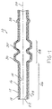
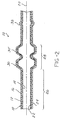
- the present invention is a multi-layer fuel line and vapor tube 10 which contains at least one bonding layer 16, at least an outer 12 and an inner layer 14.
- the tubing 10 of the present invention is defined by at least one corrugated region 28 located in its length to accommodate bending, flexing or twisting.
- the multi-layer tubing 10 with localized corrugated regions 28 can be produced by a process in which linear tubing material having multiple laminated layers is formed by coextrusion and is molded to provide the corrugation and contour desired.
- the tubing 10 may either be co-extruded to a suitable length or may be co-extruded in continuous length and cut to fit the given application subsequently.
- the tubing of the present invention may have an outer diameter up to 50 mm. However, in applications such as fuel lines and vapor recovery systems, outer diameters of up to 50.8 mm (2 inches) are preferred.
- the material may have any suitable wall thickness desired. However, in automotive systems such as those described herein, wall thicknesses between 0.5 mm and 2.0 mm are generally employed with wall thicknesses of approximately 0.8 to 1.5 mm being preferred. While it is within the scope of this invention to prepare tubing having a plurality of overlaying layers of various thermoplastic materials, the tubing 10 of the present invention generally has a maximum of five layers inclusive of the bonding layers. In the preferred embodiment, the tubing 10 has three or four layers.
- the tubing 10 of the present invention is a material which is suitable for use in motor vehicles and comprises a relatively thick outer layer 12 which is nonreactive with the external environment and can withstand various shocks, vibrational fatigue, and changes in temperature as well as exposure to various corrosive or degradative compounds to which it would be exposed through the normal course of operation of the motor vehicle.
- both the outer layer 12 as well as any interior layers bonded thereto would be suitable for use at an outer service temperature range between about -40°C and about 150°C, with a range of - 20°C to 120°C being preferred.
- the various layers of the tubing 10 are integrally laminated to one another and resistant to delamination throughout the lifetime of the tubing 10.
- the multi-layer tubing 10 will have a tensile strength of no less than 25 N/mm 2 and an elongation value at break of at least 150%.
- the tubing 10 will have a burst strength at 23°C and 120°C of at least 20 bar.
- the multi-layer tubing 10 of the present invention is sufficiently resistant to exposure to brake fluid, engine oil and peroxides such as those which may be found in gasoline.
- the outer layer 12 may be composed of any melt-processible extrudable thermoplastic material which is resistant to ultra violet degradation extreme changes in heat and exposure to environmental hazards such as zinc chloride, and degradation upon contact with engine oil and brake fluid.
- the outer layer 12 is selected from the group consisting of 12 carbon block polyamides, 11 carbon block polyamides, as well as zinc chloride resistant 6 carbon block polyamides thermoplastic elastomers.
- thermoplastic elastomers are compositions and commercially available under tradenames such as SANTOPRENE®, KRATON®, SARLINK and VICHEM. These materials which compose the outer layer 12 can be present in their unmodified state or can be modified with various plasticizers, flame retardants and the like in manners which would be known to one reasonably skilled in the art.
- a polyamide such as Nylon 12 can be effectively employed. It is anticipated that a thermoplastic such as Nylon 12 may be either modified or unmodified. If modified, it is anticipated that the material will contain various plasticizers as are readily known in the art. In the preferred embodiment, the polyamide will contain up to 17% by composition weight plasticizer; with amounts between about 1% and about 13% being preferred.
- the outer layer 12 when using Nylon 12 preferably has a wall thickness between about 0.5 mm and about 0.9 mm with a preferred range being between about 0.7 and about 0.8 mm. As indicated previously, the material is extruded by conventional co-extrusion methods to any continuous length desired.
- the outer layer 12 consists essentially of 6-carbon block polyamides, such as Nylon 6, which are resistant to degradation upon exposure to zinc chloride.
- the Nylon 6 which composes the outer 12 layer can be employed can also be modified with various plasticizers, flame retardants and the like in manners which would be known to one reasonably skilled in the art.
- the outer layer 12 is composed of a polyamide thermoplastic derived from the condensation polymerization of caprolactam. Such materials are commonly referred to as 6-carbon block polyamides or Nylon 6.
- the 6-carbon block polyamide either inherently exhibits zinc chloride resistance or contains sufficient quantities of modifying agents to impart a level of zinc chloride resistance greater than or equal to that required by Performance Requirement 9.6 as outlined in SAE Standard J844, i.e. non-reactivity after 200 hour immersion in a 50% by weight zinc chloride solution.
- the 6-carbon block polyamide material is a multi-component system comprised of a Nylon-6 copolymer blended with other Nylons and olefinic compounds.
- the zinc-chloride resistant Nylon-6 of choice will have a melt temperature between about 220°C and 240°C.
- thermoplastic materials suitable for use in the tubing 10 of the present invention are materials which can be obtained commercially under the tradenames M-7551 from NYCOA Corporation and ALLIED 1779 from Allied Chemical.
- the 6-carbon black polyamide may, optionally, include other modifying agents such as various plasticizing agents generally present in amounts between about 1.0% and about 13% by total weight of the thermoplastic composition, as are readily known in the art.
- the polyamide material employed, preferably, is an impact-modified material capable of withstanding impacts of at least 2 foot-pounds at temperatures below about -20°C.
- the Nylon 6 or the Nylon 12 is continuously extruded from a suitable coextrusion head with a wall thickness sufficient to accommodate localized expansion and elongation in molded and contoured regions.
- the contoured regions may evidence or experience a degree of localized stretching or thinning but will have sufficient initial thickness to withstand the expansion without compromising the integrity of the multi-layer wall structure.
- the outer layer is extruded to an initial wall thickness between about 0.5 mm and about 2.5 mm with a preferred thickness between about 0.75 mm and about 1.25 mm.
- thermoplastic material employed in the inner layer 14 of the present invention is a melt-processible extrudable thermoplastic material resistant to extreme changes in heat and exposure to chemical intervals such as are found in engine oil and brake fluid.
- the preferred material will have an elongation value at break of at least 150%.
- thermoplastic material of choice is, preferably, chemically similar in structure and composition to the thermoplastic material employed in the thick outer layer 12.
- chemically similar material is defined as a thermoplastic material selected from the group consisting of 12 carbon block polyamides, 11 carbon block polyamides as well as zinc chloride resistant 6 carbon block polyamides, thermoplastic elastomers and mixtures thereof.
- the thermoplastic elastomers which can successfully be employed in the tubing 10 of the present invention are compositions commercially available under tradenames such as SANTOPRENE®, KRATON®, SARLINK and VICHEM.
- the thermoplastic material employed in the inner layer 14 of the tubing 10 of the present invention either may be identical to the material employed in the thick outer layer 12 or may be a different thermoplastic selected from those listed to take advantage of specific properties of the various thermoplastics.
- the inner layer 14 is composed of a material similar to or identical to the thick outer layer 12.
- Polyamides such as Nylon 12 can be effectively employed.
- a polyamide derived from the condensation polymerization of caprolactam can be employed. Suitable materials are commonly referred to as 6-carbon block polyamides or Nylon 6.
- the 6-carbon block polyamides employed herein may contain sufficient quantities of modifying agents to impart a level of zinc chloride resistance greater than or equal to that required by test method SAE J844: i.e. non-reactivity after 200 hour immersion in a 50% by weight aqueous zinc chloride solution.
- thermoplastic employed in the inner layer 14 may be either modified or unmodified. If modified, it is anticipated that the material will contain various plasticizers as are readily known in the art. In the preferred embodiment, the polyamide will contain up to 17% by composition weight plasticizer; with amounts between about 1% and about 13% being preferred.
- 6-carbon block polyamide material is employed, it is generally part of a multi-component system comprised of a Nylon-6 copolymer blended with other Nylons and olefinic compounds.
- the 6-carbon block polyamide material of choice is preferably resistant to zinc chloride and has a melt temperature between about 220°C and 240°C.
- thermoplastic materials suitable for use in the tubing 10 of the present invention are propriety materials which can be obtained commercially under the tradenames M-7551 from NYCOA Corporation and ALLIED 1779 from Allied Chemical.
- 6-carbon block polyamide material includes plasticizing agents
- these materials are generally present in amounts between about 1.0% and about 13% by total weight of the thermoplastic composition.
- the inner layer 14 may have a thickness sufficient to supply strength and chemical resistance properties to the multi-layer tubing 10. Specifically, the inner layer 14 is of sufficient thickness to impede permeation of aliphatic and aromatic hydrocarbon molecules and migration of those molecules through to the thick outer layer 12. In the present invention, the inner layer 14 has a wall thickness less than that of the thick outer layer 12. In the preferred embodiment, the inner layer 14 has a wall thickness between about 40% and 60% that of the outer layer 12; between about 0.05 mm and about 0.2 mm; with a wall thickness between about 0.05 mm and about 0.17 mm being preferred.
- the inner layer 14 may also, optionally, contain suitable material in sufficient quantities to impart electrostatic conductivity characteristics to the tubing 10 of the present invention.
- the material is preferably capable of dissipation of electrostatic charges in the range of 10 4 to 10 9 Ohm/cm 2 .
- the thermoplastic material employed in the present invention may include, in its composition, a conductive media in sufficient quantity to permit electrostatic dissipation in the range defined.
- the conductive media may be any suitable material of a composition and shape capable of effecting this static dissipation.
- the conductive material may be selected from the group consisting of elemental carbon, stainless steel and highly conductive metals such as copper, silver, gold, nickel, silicon and mixtures thereof.
- the term "elemental carbon” as used herein is employed to describe and include materials commonly referred to as "carbon black”. The carbon black can be present in the form of carbon fibers, powders, spheres, and the like.
- the amount of conductive material contained in the thermoplastic is generally limited by considerations of low temperature durability and resistance to the degradative effects of the gasoline or fuel passing through the tubing 10.
- the amount of conductive material employed may be that amount sufficient to impart electrostatic dissipation characteristics to the tubing 10.
- the maximum amount of conductive material in the thermoplastic material is less than 5% by volume.
- the conductive material can either be blended into the crystalline structure of the polymer or can be incorporated during the polymerization of monomers which make up the thermoplastic therewith. Without being bound to any theory, it is believed that carbon-containing materials such as carbon black may be incorporated during polymerization of the surrounding thermoplastic material. Materials such as stainless steel are more likely to be blended into the crystalline structure of the polymer.
- the tubing 10 of the present invention also includes at least one intermediate layer 16 interposed between the two previously described layers and co-extruded therewith which is capable of achieving a suitable homogeneous bond between itself and the two respective layers.
- the inner layer 14 is permanently and uniformly bonded to the outer layer 12 by the intermediate bonding layer 16.
- the intermediate bonding layer 16 is generally composed of a more elastic material than that employed in the inner layer 14.
- the interior bonding layer 16 is a chemically dissimilar, permeation resistant, chemical resistant, fuel resistant thermoplastic material which is melt-processible in normal ranges of extrusion, i.e. about 175° to about 250°C.
- the material of choice has an elongation value at break greater than about 150% with an elongation value at break between about 150% and about 250% being preferred.
- chemically dissimilar it is meant that the intermediate bonding layer 16 is a non-polyamide material which is capable of integral adhesion with and between the thick outer layer 12 and the inner layer 14 as a result of co-extrusion.
- the intermediate bonding layer 16 is composed of a thermoplastic material which permits the establishment of a homogeneous bond between the inner layer 14 and outer layer 12 and exhibits properties of resistance to permeation of aliphatic and aromatic materials such as those found in fuel.
- the thermoplastic material employed herein is preferably a melt-processible co-extrudable thermoplastic which may or may not contain various plasticizers and other modifying agents.
- the thermoplastic material which comprises the intermediate bonding layer 16 is a thermoplastic polyester derived from ethylene glycol selected from the group consisting of polybutylene terephthalate, polyethylene terephthalate, polyteremethylene terephthalate, co-polymers of substituted or unsubstituted alkenes having less than four carbon atoms and vinyl alcohol, copolymers of alkenes having less than four carbon atoms and vinyl acetate, an mixtures thereof.
- the preferred material is selected from the group consisting of polybutylene terephthalate and copolymers of ethylene and vinyl alcohol having an ethylene content between about 27% and about 35% by weight.
- ethylene vinyl alcohol copolymers polymers with an ethylene content between about 27% and about 32% are preferred.
- Suitable polybutylene terephthalate material is commercially available under the tradename 1607 ZE40 from Hüls of Dusseldorf, Germany.
- Suitable EVA materials which can be employed in the tubing of the present invention include ethylene vinyl alcohol commercially available from EVA/LA.
- the material employed in the intermediate bonding layer 16 can, optionally, exhibit conductive characteristics rendering it is capable of dissipation of electrostatic charges in the range of 10 -4 to 10 -9 Ohm/cm 2 .
- the thermoplastic material employed in the present invention may include, in its composition, a conductive media in sufficient quantity to permit electrostatic dissipation in the range defined.
- the conductive media may be any suitable material of a composition and shape capable of effecting this static dissipation.
- the conductive material may be selected from the group consisting of elemental carbon, stainless steel and highly conductive metals such as copper, silver, gold, nickel, silicon and mixtures thereof.
- the term "elemental carbon” as used herein is employed to describe and include materials commonly referred to as "carbon black”. The carbon black can be present in the form of carbon fibers, powders, spheres, and the like.
- the amount of conductive material contained in the thermoplastic is generally limited by considerations of low temperature durability and resistance to the degradative effects of the gasoline or fuel passing through the tubing 10.
- the amount of conductive material employed may be that amount sufficient to impart electrostatic dissipation characteristics to the tubing 10.
- the maximum amount of conductive material in the thermoplastic material is less than 5% by volume.
- the conductive material can either be blended into the crystalline structure of the polymer or can be incorporated during polymerization of monomers that make up the polymer. Without being bound to any theory, it is believed that carbon-containing materials such as carbon black may be incorporated during the polymerization of the surrounding thermoplastic material. Materials such as stainless steel are more likely to be blended into the crystalline structure of the polymer.
- thermoplastic material employed in the bonding layer 16 also exhibits characteristics which permit resistance to permeation by short chain aromatic and aliphatic compounds. These permeation resistant characteristics synergistically interact with the inner polyamide layer 14 such that the total permeation resistance is unexpectedly increased when the thermoplastic bonding layer 16 is bonded to the inner polyamide layer 14. Thus, the resistance to permeation to short chain aromatic and aliphatic hydrocarbons exhibited by the multi-layer tubing 10 exceeds the permeation resistance exhibited by individual layers of either polybutylene terephthalate or polyamide of a thickness equal to or greater than the multi-ply composite of the present invention.
- the material employed in the inner layer 14 generally has a degree of expansion greater than that of the outer layer 12.
- the elongation value at break of the inner layer is between about 150% and about 250%.
- the material generally has an elastic memory which can result in the contraction of the material to about 200% of its elongated value upon stretching or other deformative activities.
- the intermediate bonding layer 16 is preferably maintained at the minimum thickness necessary to achieve effective bonding between the inner layer 14 and outer layer 12. Furthermore, the intermediate bonding layer 16 can also function in concert with the inner layer 14 to prevent permeation of the fuel through the tubing 10. As indicated previously, it is preferred that the amount of hydrocarbon permeation not exceed 0.5 gm/m 2 in a 24 hour interval. Thus where the bonding layer 16 contributes to permeation resistance, it is anticipated that the thickness of the inner layer 14 and intermediate bonding layer 16 can be modified to accomplish this end.
- the intermediate bonding layer 16 can also exhibit resistance to the permeation of aliphatic and aromatic compounds therethrough. Furthermore the intermediate bonding layer 16 may exhibit conductive or static dissipative characteristics such as those described previously. Thus the intermediate bonding layer 16 may optionally include sufficient amounts of conductive media to effect electrostatic dissipation in the range of 10 -4 to 10 -9 Ohm/cm 2 . As with the inner layer 14, the intermediate bonding layer 16 may be inherently electrostatically dissipative or may be rendered so by the inclusion of certain conductive materials such as those selected from the group consisting of elemental carbon, stainless steel, copper, silver, gold, nickel, silicon, and mixtures thereof.
- the intermediate bonding layer 16 is of sufficient thickness to permit an essentially homogeneous bond between the inner layer 14 and outer layer 12.
- the intermediate bonding layer 16 can be thinner than the other two layers and can constitute between about 10% and about 50% of the total wall thickness or between about 20% and about 30% of the thickness of the outer layer 12.
- the thickness of the intermediate bonding layer 16 is between about 0.05 mm and about 0.2 mm with a thickness between about 0.05 mm and about 0.2 mm being preferred.
- the multi-layer tube 10 of the present invention is composed of an elongated cylindrical wall 18 which preferably has an essentially circular cross-section perpendicular to its longitudinal axis 20.
- the cylindrical wall 18 has an essentially uniform wall thickness throughout its length and circumference and is defined by an inner surface 22 and an opposed outer surface 24.
- the inner surface 22 defines an essentially cylindrical opening which extends longitudinally through the tubing 10 of the present invention essentially coaxial to the longitudinal axis 20.
- the cylindrical wall 18 of the multi-layer tube 10 comprises at least two distinct regions.
- the cylindrical wall 18 has a first region 26 where the cylindrical wall 18 is essentially parallel to the longitudinal axis 20. Contiguous to the first region 26 is a second region 28 which is defined by at least one convolution or corrugation 30 in the cylindrical wall 18.
- the term convolution is defined as an area of cylindrical wall 18 which deviates from parallel to the longitudinal axis 20, and preferably deviates outward from a position parallel to the longitudinal axis 20. This deviation can produce an inner diameter which is between about 20% and 300% greater than the inner diameter of the first region 26 at its maximum. In the preferred embodiment, the inner diameter of the convolution 30 is between 20% and 100% greater than the inner diameter of the first region 26.
- the tubing 10 of the present invention can have as many convolutions with any length of cylindrical tubing optionally interposed therebetween as would be necessary to achieve the degree of flexibility required.
- the geometry of the convolutions can be of any cross-sectional profile desired.
- the convolutions 30 may have angled, squared, or sinusoidal profiles as desired.
- the tubing 10 of the present invention will have sufficient convolutions positioned on the length of the tubing 10 to accommodate bends of over 90° from vertical. It is to be understood that the tubing 10 of the present invention can be customized to suit the end user. Thus, in situations were such acute bends are not required, the tubing can have fewer or shallower convolutions.
- a longitudinal area on one side of the second region 26 can be compressed so that the segments of the various convolutions 30 are brought into lateral contact with one another while the diametrically opposed longitudinal area is reciprocally elongated.
- the tubing 10 may also include various molded flanges and the like such as hose barb 38 shown in the Figure. It is to be understood that in hose barb 38, as in all molded regions, the wall thickness remains essentially constant linearly throughout the outwardly expanded region as do the relative thicknesses of the various multiple layers.
- the present invention is a multi-layer tubing material which can accommodate the introduction of various bends and contours during installation.
- the material thus produced is durable and resistant to delamination during installation and use.
- the present invention discloses an elongated multi-layer tubing for connection to a motor vehicle system for handling fluids containing hydrocarbons.
- the tube is defined by a wall having essentially parallel inner and outer surfaces.
- the inner surface defines an essentially unobstructed longitudinally extending passage within an interior of the tubing.
- the wall has a longitudinally extending first region with an essentially uniform cross-sectional configuration and a longitudinally extending second region with at least one corrugation of a varying cross-sectional configuration.
- the second region has a cross-sectional area at least as large as a cross-sectional area of the first region.
- the second region permits bending of the tubing such that the longitudinal axis of the tubing is non-linear.
- the wall is formed by multiple layers of essentially constant thicknesses bonded permanently and uniformly to one another throughout the first and second regions.
- the multiple layers include a first layer consisting essentially of an extrudable, melt-processible thermoplastic having an elongation value at break of at least 150% and an ability to withstand impacts of at least 2 foot-pounds at temperatures below about -20°C, a second layer homogeneously bonded to the first layer, the second layer consisting essentially of an extrudable, melt-processible thermoplastic resistant to permeation by short-chain hydrocarbons, the second layer consisting essentially of a thermoplastic chemically dissimilar to the thermoplastic employed in the first layer and capable of sufficiently permanent laminar adhesion to the first layer to prevent delamination during a desired lifetime of the tubing, and a third layer consisting essentially of an extrudable, melt-processible thermoplastic homogeneously bonded to the second layer, the third layer capable of sufficiently permanent laminar adhesion to the second layer to prevent delamination during the desired lifetime of the tubing, the extrudable, melt-processible thermoplastic material of the third layer having an elongation value
- SANTOPRENE® commercially available from Advanced Elastomer Systems, L.P. of St. Louis, Missouri is a thermoplastic rubber FR grade. Aside from the thermoplastic rubber, it also contains antimony trioxide flame retardant, and may contain carbon black, CAS No. 1333-86-4.
- SANTOPRENE® thermoplastic rubber may react with strong oxidizing chemicals, and also reacts with acetal resins at temperatures of 425°F and above, producing decomposition of the acetal resins, and formaldehyde as a decomposition product. Decomposition of halogenated polymers and phenolic resins may also be accelerated when they are in contact with SANTOPRENE® thermoplastic rubber at processing temperatures.
- SANTOPRENE® Physical characteristics include a slightly rubber-like odor, and the appearance of black or natural (colorable) pellets. It is thermally stable to 500°F.
- the flash ignition temperature is greater than 650°F by method ASTM-D 1929-77, and by the same method, self-ignition temperature is above 700°F.
- the typical specific gravity is 0.90 to 1.28.
- the material has various hardnesses which are suitable in the present invention, however, in the preferred embodiment, the SANTOPRENE® thermoplastic rubber having an 80 Shore A hardness is utilized.
- the SANTOPRENE® thermoplastic rubber is designed to offer fluid and oil resistance equivalent to that of conventional thermoset rubbers such as neoprene.
- the resistance of the SANTOPRENE® rubber grades to oils can be classified by using the SAE J200/ASTM D2000 standard classification system for rubber.
- the vinyl compounds from Vichem Corporation of Allendale, Michigan are polyvinyl chloride compounds composed of a vinyl resin and functioning additives.
- the ingredients include a stabilizer, a resin CAS No. 75-01-4, a plasticizer CAS No. 68515-49-1, an epoxy soya oil CAS No. 8013-07-8, a filler CAS No. 1317-65-3 and carbon black CAS No. 1333-85-4.
- the specific gravity is 1.35 and the compound has the appearance of pellets and has a characteristically bland odor.
- KRATON® is a thermoplastic rubber having a specific gravity of 0.90 to 1.90 and a hardness of 15A to 60D.
- the tensile strength is up to 2,500 psi.
- the elongation is up to 750% and the tear strength is up to 750 pli (130 kN/m).
- the flex modulus is 750 to 100,000 psi.
- the service temperature is -70°C to 150°C.
- the ozone resistance is excellent, UV resistance is excellent, fluid resistance is fair to excellent, and flame resistance is fair to excellent.
- SARLINK is a thermoplastic elastomer commercially available from Novacor Chemicals Inc. of Leominster, Massachusetts.
- the specific gravity ranges from 1.13 to 1.22.
- the modulus at 100% ranges between 260 and 570 psi.
- the tensile strength ranges between 780 and 2,060 psi.
- the ultimate elongation ranges between about 345 and about 395%.
- the tear strength ranges between about 81 and about 196 pli.
- the tension set ranges between about 4 and 6%. It has excellent fluid resistance to acids and alkalis, aqueous solutions, organic solvents, petroleum oils and fuels, automotive fluids such as automatic transmission, power steering, etc. and industrial fluids.
- the SARLINK product is a solid, black pellet material with a mildly pungent odor. It is insoluble in water at 20°C.
Landscapes
- Engineering & Computer Science (AREA)
- General Engineering & Computer Science (AREA)
- Mechanical Engineering (AREA)
- Manufacturing & Machinery (AREA)
- Laminated Bodies (AREA)
- Rigid Pipes And Flexible Pipes (AREA)
Applications Claiming Priority (3)
| Application Number | Priority Date | Filing Date | Title |
|---|---|---|---|
| US227511 | 1994-04-10 | ||
| US08/227,511 US5469892A (en) | 1992-04-14 | 1994-04-10 | Corrugated polymeric tubing having at least three layers with at least two respective layers composed of polymeric materials dissimilar to one another |
| EP95915639A EP0755493B1 (fr) | 1994-04-10 | 1995-04-10 | Tube à plusieurs couches, propre à l'usage dans véhicules automobiles |
Related Parent Applications (1)
| Application Number | Title | Priority Date | Filing Date |
|---|---|---|---|
| EP95915639.9 Division | 1995-10-19 |
Publications (2)
| Publication Number | Publication Date |
|---|---|
| EP1209399A2 true EP1209399A2 (fr) | 2002-05-29 |
| EP1209399A3 EP1209399A3 (fr) | 2004-01-21 |
Family
ID=22853385
Family Applications (2)
| Application Number | Title | Priority Date | Filing Date |
|---|---|---|---|
| EP02001200A Withdrawn EP1209399A3 (fr) | 1994-04-10 | 1995-04-10 | Tube polymère à nervure dotée d'au moins trois couches dont au moins deux de matériaux polymères différents |
| EP95915639A Revoked EP0755493B1 (fr) | 1994-04-10 | 1995-04-10 | Tube à plusieurs couches, propre à l'usage dans véhicules automobiles |
Family Applications After (1)
| Application Number | Title | Priority Date | Filing Date |
|---|---|---|---|
| EP95915639A Revoked EP0755493B1 (fr) | 1994-04-10 | 1995-04-10 | Tube à plusieurs couches, propre à l'usage dans véhicules automobiles |
Country Status (6)
| Country | Link |
|---|---|
| US (1) | US5469892A (fr) |
| EP (2) | EP1209399A3 (fr) |
| JP (1) | JP2968045B2 (fr) |
| BR (1) | BR9507378A (fr) |
| DE (1) | DE69527198T2 (fr) |
| WO (1) | WO1995027866A1 (fr) |
Cited By (1)
| Publication number | Priority date | Publication date | Assignee | Title |
|---|---|---|---|---|
| DE202004019464U1 (de) * | 2004-12-15 | 2006-04-20 | Fränkische Rohrwerke Gebr. Kirchner Gmbh & Co. Kg | Kunststoffrohr, insbesondere Kunststoffwellrohr |
Families Citing this family (95)
| Publication number | Priority date | Publication date | Assignee | Title |
|---|---|---|---|---|
| US5865218A (en) * | 1992-04-14 | 1999-02-02 | Itt Corporation | Multi-layer fuel and vapor tube |
| US6378562B1 (en) * | 1992-04-14 | 2002-04-30 | Itt Industries, Inc. | Multi-layer tubing having electrostatic dissipation for handling hydrocarbon fluids |
| US5427831B1 (en) * | 1993-11-12 | 1998-01-06 | Du Pont | Fluoropolymer laminates |
| US5590691A (en) * | 1994-05-02 | 1997-01-07 | Itt Corporation | Extruded multiple plastic layer coating bonded to a metal tube |
| FR2720472B1 (fr) * | 1994-05-31 | 1996-07-12 | Hutchinson | Tuyau de transport de carburant. |
| US5542834A (en) * | 1994-11-10 | 1996-08-06 | Lupke; Manfred A. A. | Skinned double wall pipe and apparatus for making same |
| BE1009397A3 (fr) * | 1995-05-12 | 1997-03-04 | Solvay | Tube ou feuille multicouche. |
| US5788341A (en) | 1995-06-06 | 1998-08-04 | Itt Automotive Electrical Systems, Inc. | Vehicle brake |
| US6155304A (en) * | 1996-01-29 | 2000-12-05 | Ti Group Automotive Systems Corp. | Reinforced flexible tubing for fluid handling systems and method |
| US6263920B1 (en) * | 1996-01-29 | 2001-07-24 | Hybritech Polymers | Multi-layer assembly for fluid and vapor handling and containment systems |
| US6192942B1 (en) * | 1996-01-29 | 2001-02-27 | Hybritech Polymers | Multi-layer tubing assembly for fluid and vapor handling systems |
| US5934336A (en) * | 1996-01-29 | 1999-08-10 | Bundy Corporation | Multi-layer tubing assembly for fluid and vapor handling systems |
| US6209587B1 (en) * | 1996-01-29 | 2001-04-03 | Hybritech Polymers | Multi-layer assembly for fluid and vapor handling and containment systems |
| US6039085A (en) * | 1996-01-29 | 2000-03-21 | Bundy Corporation | Multi-layer tubing assembly with foamed outer layer |
| US6176268B1 (en) | 1996-01-29 | 2001-01-23 | Hybritech Polymers | Multi-layer assembly for fluid and vapor handling and containment systems |
| US6012496A (en) * | 1996-01-29 | 2000-01-11 | Hybritech Polymers | Multi-layer tubing assembly for fluid and vapor handling systems |
| US5931201A (en) * | 1996-01-29 | 1999-08-03 | Bundy Corporation | Multi-layer tubing assembly for fluid and vapor handling systems |
| US5660899A (en) * | 1996-02-21 | 1997-08-26 | Safe-T-Quip Corporation | Convoluted heat-reflective, protective sleeving |
| JP3261969B2 (ja) * | 1996-02-29 | 2002-03-04 | 豊田合成株式会社 | ホースとその製造方法 |
| US5891373A (en) * | 1996-05-23 | 1999-04-06 | Eagle-Picher Industries, Inc. | Process of making a multi-layer tube |
| KR100340611B1 (ko) * | 1996-06-05 | 2002-10-19 | 아토피나 | 개선된인장강도를갖는굴곡성열가소성수지 |
| US6123113A (en) * | 1997-05-01 | 2000-09-26 | Itt Manufacturing Enterprises, Inc. | Asymmetrical convolute tube |
| US6199916B1 (en) | 1997-05-15 | 2001-03-13 | Itt Manufacturing Enterprises, Inc. | Spin welded fluid connector |
| FR2772776B1 (fr) | 1997-12-23 | 2002-03-29 | Atochem Elf Sa | Compositions antistatiques a base de polyamide |
| DE19819565A1 (de) | 1998-04-30 | 1999-11-11 | Inventa Ag | Antistatische und peroxidstabile Formmassen |
| US5960977A (en) * | 1998-05-14 | 1999-10-05 | Itt Manufacturing Enterprises, Inc. | Corrugated polymeric filler neck tubing |
| DE69937151T2 (de) * | 1998-07-29 | 2008-06-19 | Aisan Kogyo K.K., Obu | Fluidversorgungsleitung |
| GB2340197A (en) * | 1998-08-06 | 2000-02-16 | Petro Technik Ltd | Flexible pipe for conveying fluids |
| US6939466B2 (en) * | 1998-08-17 | 2005-09-06 | Cuno Incorporated | Graded particle-size retention filter medium for fluid filtration unit with improved edge seal |
| US5957164A (en) * | 1998-09-10 | 1999-09-28 | Aeroquip Corporation | Refrigerant hose |
| CA2352663C (fr) | 1998-12-21 | 2008-07-29 | Parker-Hannifin Corporation | Construction de tuyau resistant a l'effondrement |
| US6742545B2 (en) | 1998-12-21 | 2004-06-01 | Parker-Hannifin Corporation | Hose construction |
| US6240970B1 (en) | 1999-04-01 | 2001-06-05 | Itt Manufacturing Enterprises, Inc. | Tubing for handling hydrocarbon materials and having an outer jacket layer adhered thereto |
| ES2262467T3 (es) * | 1999-04-16 | 2006-12-01 | Ube Industries, Ltd. | Tubo de combustible de multiple capa. |
| US6584959B2 (en) | 1999-05-27 | 2003-07-01 | Itt Manufacturing Enterprises, Inc. | Thick walled convoluted tubing for use in fuel feed and return applications |
| US6276400B1 (en) | 1999-06-08 | 2001-08-21 | Itt Manufacturing Enterprises, Inc. | Corrosion resistant powder coated metal tube and process for making the same |
| US6279615B1 (en) | 1999-09-03 | 2001-08-28 | Tokai Rubber Industries, Ltd. | Fuel hose |
| US20040226623A1 (en) * | 1999-10-12 | 2004-11-18 | Oem/Miller, A Division Of Holm Industries | Dual wall co-extruded corrugated tubing |
| ATE314599T1 (de) * | 1999-10-29 | 2006-01-15 | Piolax Inc | Gewelltes harzrohr |
| US6354331B1 (en) | 1999-11-08 | 2002-03-12 | Parker-Hannifin Corp. | Flexible plastic tubing construction having a sight glass window |
| FR2801365B1 (fr) * | 1999-11-19 | 2002-06-14 | Nobel Plastiques | Tuyau multicouche en matiere plastique pour transfert de fluide du genre carburant |
| US6230749B1 (en) | 1999-11-29 | 2001-05-15 | Norma Products (Us) Inc. | Multilayer tube |
| DE10110964C2 (de) * | 2000-06-09 | 2002-10-31 | Ems Chemie Ag | Thermoplastische Mehrschichtverbunde |
| US6555243B2 (en) * | 2000-06-09 | 2003-04-29 | Ems-Chemie Ag | Thermoplastic multilayer composites |
| US6830076B1 (en) * | 2000-08-02 | 2004-12-14 | The Boeing Company | Self-compensating hybrid combination ducts |
| US6670004B1 (en) | 2000-08-02 | 2003-12-30 | Saint-Gobain Performance Plastics Corporation | Laminated nylon air brake tubing |
| ES2274755T3 (es) * | 2000-08-02 | 2007-06-01 | Ti Automotive (Fuldabruck) Gmbh | Tuberia de vehiculo automovil. |
| EP1197699A3 (fr) * | 2000-09-20 | 2003-05-21 | Tokai Rubber Industries, Ltd. | Tuyau flexible pour hydrogène |
| EP1290368A4 (fr) * | 2000-10-13 | 2004-10-06 | Oem Miller Division Of Holm In | Tuyau ondule co-extrude a double paroi |
| DE20021348U1 (de) * | 2000-12-16 | 2001-05-10 | Pluggit Int Nv | Kanalrohr |
| JP3606204B2 (ja) * | 2001-01-19 | 2005-01-05 | 日産自動車株式会社 | 樹脂製チューブ |
| JP2003033983A (ja) * | 2001-05-15 | 2003-02-04 | Tokai Rubber Ind Ltd | 燃料ホース |
| EP1421660A2 (fr) * | 2001-08-09 | 2004-05-26 | Federal-Mogul Powertrain, Inc. | Gaine de protection souple amortie |
| FR2829221B1 (fr) * | 2001-09-04 | 2006-11-03 | Nobel Plastiques | Tuyau coude, produit intermediaire en forme de tuyau rectiligne et procede pour couder ce produit intermediaire |
| US20030145896A1 (en) * | 2002-02-06 | 2003-08-07 | Saint-Gobain Performance Plastics Corporation | Coiled laminated air brake tubing |
| US6823898B1 (en) | 2002-06-03 | 2004-11-30 | Itt Manufacturing Enterprises, Inc. | Low cost, low permeation multi-layer tubing |
| US20050155662A1 (en) * | 2002-06-03 | 2005-07-21 | Tao Nie | Low-cost, low permeation multi-layer tubing having intermediate polymeric alloy layer |
| US20040058111A1 (en) * | 2002-09-23 | 2004-03-25 | Saint-Gobain Performance Plastics Corp. | Compounded nylon 6, nylon 12 material for air brake systems |
| US7357968B2 (en) * | 2002-09-27 | 2008-04-15 | Itt Manufacturing Enterprises, Inc. | Reinforced, high pressure, low permeation multilayer hose |
| US20040096615A1 (en) * | 2002-11-18 | 2004-05-20 | Saint-Gobain Performance Plastics Corp. | Hose comprising modified nylon 6,12 material |
| JP2004169851A (ja) * | 2002-11-21 | 2004-06-17 | Sanoh Industrial Co Ltd | 多層チューブ |
| AU2003287202A1 (en) * | 2002-11-26 | 2004-06-18 | Parker-Hannifin Corporation | Tubular polymeric composites for tubing and hose constructions |
| EP1449885B1 (fr) | 2003-02-18 | 2013-10-02 | Arkema France | Utilisation de nanotubes de carbone dans des mélanges de polyamide et de polyoléfine |
| KR101118818B1 (ko) * | 2003-02-28 | 2012-06-13 | 이엠에스-케미에 아게 | 중공 본체 형상의 열가소성 다층 복합물 |
| EP1631469B1 (fr) * | 2003-06-11 | 2008-06-18 | Kautex Textron GmbH & Co. KG. | Tube de remplissage en plastique forme par extrusion-soufflage |
| EP2277675B1 (fr) * | 2003-08-19 | 2012-04-04 | Solvay Specialty Polymers USA, LLC. | Corps creux en polyamide antichoc |
| JP2005129363A (ja) * | 2003-10-23 | 2005-05-19 | Nitta Moore Co | 燃料電池用純水配管 |
| US6902208B1 (en) * | 2003-12-10 | 2005-06-07 | Dayco Product, Llc | Gas impermeable tube joint and method of forming same |
| DE102004029011A1 (de) * | 2004-06-16 | 2006-01-12 | Ems-Chemie Ag | Polymermischung aus aliphatischen Polyamiden und teilaromatischen Polyamiden und deren Verwendung |
| FR2876109B1 (fr) * | 2004-10-05 | 2006-11-24 | Arkema Sa | Polyamides semi-cristallins souples |
| US8733405B2 (en) | 2005-03-14 | 2014-05-27 | Advanced Drainage Systems, Inc. | Corrugated pipe with outer layer |
| US7484535B2 (en) * | 2005-03-14 | 2009-02-03 | Advanced Drainage Systems, Inc. | Corrugated pipe with outer layer |
| JP2007046772A (ja) * | 2005-07-13 | 2007-02-22 | Toyoda Gosei Co Ltd | 樹脂パイプおよび樹脂成形品 |
| FR2909433B1 (fr) | 2006-11-30 | 2014-01-10 | Arkema France | Utilisation d'une structure multicouche pour la fabrication de conduites de gaz, notamment de methane. |
| CA2622692C (fr) | 2007-02-26 | 2015-10-06 | Advanced Drainage Systems, Inc. | Matrice de tuyau double paroi a rapport defini |
| CA2622695C (fr) | 2007-02-26 | 2015-11-03 | Advanced Drainage Systems, Inc. | Appareil et methode de voie d'acheminement de filiere d'extrusion pour tubes |
| US8820801B2 (en) | 2007-11-16 | 2014-09-02 | Advanced Drainage System, Inc. | Multi-wall corrugated pipe couplings and methods |
| US8820800B2 (en) | 2007-11-16 | 2014-09-02 | Advanced Drainage Systems, Inc. | Multi-wall corrugated pipe couplings and methods |
| US8114324B2 (en) | 2008-10-14 | 2012-02-14 | Advanced Drainage Systems, Inc. | Apparatus and method for pressing an outer wall of pipe |
| US7988438B2 (en) | 2008-02-11 | 2011-08-02 | Advanced Drainage Systems, Inc. | Extrusion die vacuum seals |
| US8550807B2 (en) | 2008-05-28 | 2013-10-08 | Advanced Drainage Systems, Inc. | In-mold punch apparatus and methods |
| WO2011011268A1 (fr) | 2009-07-24 | 2011-01-27 | Parker-Hannifin Corporation | Ensemble tuyau résistant au feu |
| US20130011595A1 (en) | 2010-04-29 | 2013-01-10 | Parker-Hannifin Corporation | Nylon airbrake tubing constructions |
| CA2809480A1 (fr) * | 2010-09-03 | 2012-03-08 | Aerazur S.A. | Tuyaux thermoplastiques pour vehicules aeriens |
| US8713944B2 (en) | 2010-09-23 | 2014-05-06 | Delavan Inc. | High temperature manifolds for gas turbine engines |
| NO336033B1 (no) * | 2011-07-12 | 2015-04-20 | Materix As | Rørkomponent med innvendig, rørformet sliteelement og framgangsmåte ved fôring av rørkomponenten med sliteelementet |
| DE102011081494A1 (de) * | 2011-08-24 | 2013-02-28 | Zf Friedrichshafen Ag | Verfahren und Vorrichtung zum Herstellen einer Balgfeder mit quer zur Längsachse der Balgfeder verlaufenden Wellen |
| AU2013237736A1 (en) * | 2012-10-25 | 2014-05-15 | Ge Oil & Gas Uk Limited | Flexible Pipe Body Layers And Method Of Producing Same |
| JP5999428B2 (ja) * | 2012-12-25 | 2016-09-28 | 矢崎総業株式会社 | 線状アッセンブリー |
| US10197207B2 (en) * | 2015-01-22 | 2019-02-05 | Hamilton Sundstrand Corporation | Conductive elastomeric flexible coupling |
| US20170074427A1 (en) * | 2015-09-16 | 2017-03-16 | Cooper-Standard Automotive, Inc. | Fuel tube for a gasoline engine |
| FR3078132B1 (fr) | 2018-02-21 | 2020-05-22 | Arkema France | Structure tubulaire annelee destinee au transport de carburant dans le reservoir |
| JPWO2020122226A1 (ja) * | 2018-12-14 | 2021-10-21 | 株式会社クラレ | 燃料パイプ及びそれを用いた燃料輸送方法 |
| JP7382149B2 (ja) * | 2019-03-19 | 2023-11-16 | 住友理工株式会社 | 多層チューブ |
| JP7304496B2 (ja) * | 2020-09-11 | 2023-07-06 | 八千代工業株式会社 | フィラーパイプおよびフィラーパイプの製造方法 |
Citations (10)
| Publication number | Priority date | Publication date | Assignee | Title |
|---|---|---|---|---|
| US4424834A (en) * | 1982-09-22 | 1984-01-10 | Kyoraku Co., Ltd. | Elastic shaped article |
| FR2579290A1 (fr) * | 1985-03-22 | 1986-09-26 | Technoform Caprano Brunnhofer | Conduite de carburant de longueur predeterminee pour l'installation a demeure dans un vehicule automobile |
| DE9001467U1 (fr) * | 1990-02-09 | 1990-04-19 | Unicor Gmbh Rahn Plastmaschinen, 8728 Hassfurt, De | |
| EP0470606A1 (fr) * | 1990-08-09 | 1992-02-12 | Ems-Inventa Ag | Conduit antistatique de carburant |
| FR2688858A3 (en) * | 1992-03-23 | 1993-09-24 | Ems Inventa Ag | Flexible pipe for high pressure |
| FR2689956A1 (fr) * | 1992-03-30 | 1993-10-15 | Tokai Rubber Ind Ltd | Tuyau de transport de carburant comportant un tube formé de couches de résine dont une contient du fluor, tube en résine pour ce tuyau et procédé pour sa fabrication. |
| WO1993025835A1 (fr) * | 1992-06-11 | 1993-12-23 | Itt Industries, Inc. | Conduites a plusieurs couches pour le carburant et les vapeurs d'essence |
| DE9319879U1 (de) * | 1993-12-23 | 1994-03-17 | Inventa Ag | Sequentiell Coextrudierte Kühlflüssigkeitsleitung |
| DE9402180U1 (de) * | 1994-02-09 | 1994-04-07 | Inventa Ag | Kühlflüssigkeitsleitung |
| WO1994009302A1 (fr) * | 1992-10-16 | 1994-04-28 | Itt Industries, Inc. | Conduite ondulee multicouche comportant au moins deux matieres polymeres differentes |
Family Cites Families (44)
| Publication number | Priority date | Publication date | Assignee | Title |
|---|---|---|---|---|
| BE632328A (fr) * | 1962-05-22 | 1900-01-01 | ||
| DE1779905B2 (de) * | 1962-05-22 | 1975-09-18 | Raybestos-Manhattan, Inc., Manheim, Pa. (V.St.A.) | Tetrafluoräthylenpolymerrohr |
| US3561493A (en) * | 1965-04-21 | 1971-02-09 | Paul Maillard | Composite tubes and method of manufacturing same |
| US3670132A (en) * | 1970-07-13 | 1972-06-13 | Dca Food Ind | Environmental control system for microwave proofer |
| DE2057709A1 (de) * | 1970-11-17 | 1972-05-31 | Mannesmann Ag | Behaelter oder Rohre aus Kunststoff zum Lagern bzw. zum Transport von Fluessigkeiten,Pasten oder rieselfaehigen Schuettguetern |
| JPS4843073A (fr) * | 1971-09-30 | 1973-06-22 | ||
| FR2194545B1 (fr) * | 1972-08-01 | 1976-01-23 | Viennot Pierre Fr | |
| US3828112A (en) * | 1973-03-14 | 1974-08-06 | Moore & Co Samuel | Composite hose for conductive fluid |
| JPS5054919A (fr) * | 1973-09-17 | 1975-05-14 | ||
| US4303457A (en) * | 1975-10-06 | 1981-12-01 | Eaton Corporation | Method of making a semi-conductive paint hose |
| IT1073477B (it) * | 1976-04-06 | 1985-04-17 | Ugine Kuhlmann | Procedimento per il trattamento del polifluoruro di vinilidene per au mentarne l aderenza ad un altro polimero |
| US4059847A (en) * | 1976-09-01 | 1977-11-22 | Dayco Corporation | Hose having an electrically conductive layer for dissipating static electricity and method of making same |
| US4330017A (en) * | 1977-04-22 | 1982-05-18 | Nissan Motor Company, Limited | Rubber hose for automotive fuel line |
| DE2830593C2 (de) * | 1978-07-12 | 1980-09-25 | Metallgesellschaft Ag, 6000 Frankfurt | Verfahren und Vorrichtung zur Innen- und Außenbeschichtung von Metallrohren |
| AU544400B2 (en) * | 1980-03-25 | 1985-05-23 | International Lead Zinc Research Organization Inc. | Zinc-aluminum alloys and coatings |
| FR2577168B1 (fr) * | 1985-02-08 | 1987-02-27 | Atochem | Composite polyfluorure de vinylidene-copolymere (ethylene-oxyde de carbone), traitement du polyfluorure de vinylidene par ce copolymere en vue de son adhesion a un substrat |
| FR2577564B1 (fr) * | 1985-02-14 | 1987-07-17 | Atochem | Procede de traitement de surface du polyfluorure de vinylidene en vue de son adhesion a un substrat. materiau obtenu a partir du polyfluorure de vinylidene traite |
| US4675780A (en) * | 1985-08-26 | 1987-06-23 | The Gates Rubber Company | Conductive fiber hose |
| US4685090A (en) * | 1985-11-27 | 1987-08-04 | Raychem Corporation | Tubular article |
| FI80853C (sv) * | 1988-06-07 | 1990-08-10 | Neste Oy | Plastbelagt stålrör |
| JPS63125885A (ja) * | 1986-11-13 | 1988-05-30 | 横浜ゴム株式会社 | 冷媒輸送用ホ−ス |
| JP2719698B2 (ja) * | 1987-04-06 | 1998-02-25 | 臼井国際産業 株式会社 | 耐食性重層被覆金属管 |
| DE3715251A1 (de) * | 1987-05-08 | 1988-12-01 | Caprano & Brunnhofer | Kraftfahrzeug-rohrleitung fuer die fuehrung eines alkoholischen mediums |
| JPS6414029A (en) * | 1987-07-08 | 1989-01-18 | Tokai Rubber Ind Ltd | Hose |
| JPH0342302Y2 (fr) * | 1987-11-10 | 1991-09-04 | ||
| US5148837A (en) * | 1988-05-30 | 1992-09-22 | Uponor N.V. | Pipe for relining underground pipelines |
| JPH02190692A (ja) * | 1989-01-18 | 1990-07-26 | Tokai Rubber Ind Ltd | ゴムホース |
| DE3901928C1 (fr) * | 1989-01-24 | 1990-03-08 | Technoform Caprano + Brunnhofer Kg, 3501 Fuldabrueck, De | |
| US5142782A (en) * | 1989-02-02 | 1992-09-01 | Teleflex Incorporated | Coated braided hose method and assembly |
| JPH03117794A (ja) * | 1989-09-29 | 1991-05-20 | Mazda Motor Corp | プラスチック製フィラーパイプ |
| DE9007303U1 (fr) * | 1989-11-20 | 1990-12-20 | Technoform Caprano + Brunnhofer Kg, 3501 Fuldabrueck, De | |
| DE4001126C1 (fr) * | 1989-11-20 | 1990-12-13 | Technoform Caprano + Brunnhofer Kg, 3501 Fuldabrueck, De | |
| DE4001125C1 (fr) * | 1989-11-20 | 1990-12-13 | Technoform Caprano + Brunnhofer Kg, 3501 Fuldabrueck, De | |
| DE3942354C2 (de) * | 1989-12-21 | 1999-01-14 | Siebe Automotive Deutschland Gmbh | Mehrschichtiger Sicherheitsschlauch aus thermoplastischen Kunststoffen für brennbare Fluide |
| DE4006870C2 (de) * | 1990-03-05 | 1998-04-23 | Inventa Ag | Kraftstoffleitung |
| US5080405A (en) * | 1990-07-10 | 1992-01-14 | Nitto Kohki Co., Ltd. | Corrugated pipe coupling |
| US5143122A (en) * | 1990-09-11 | 1992-09-01 | Bundy Corporation | Composite flexible conduit assembly |
| JPH04129832A (ja) * | 1990-09-19 | 1992-04-30 | Mazda Motor Corp | 樹脂製燃料給油管 |
| JPH05118478A (ja) * | 1991-03-14 | 1993-05-14 | Seiji Nagayoshi | 可撓性複合樹脂管 |
| US5170011A (en) * | 1991-09-25 | 1992-12-08 | Teleflex Incorporated | Hose assembly |
| JPH085167B2 (ja) * | 1992-01-06 | 1996-01-24 | パイロット インダストリーズ、インコーポレイテッド | フルオロポリマー複合材料製チューブおよびその製造方法 |
| US5284184A (en) * | 1992-04-14 | 1994-02-08 | Itt Corporation | Corrugated multi-layer tubing having at least one fluoroplastic layer |
| EP1122059A3 (fr) | 1992-04-14 | 2003-03-05 | Itt Manufacturing Enterprises, Inc. | Tubulure de carburant et de vapeur à plusieurs couches |
| DE4400811C2 (de) * | 1994-01-13 | 2001-10-11 | Fulton Rohr Gmbh & Co Kg | Rohrleitung für Systeme in Kraftfahrzeugen und Herstellungsverfahren |
-
1994
- 1994-04-10 US US08/227,511 patent/US5469892A/en not_active Expired - Lifetime
-
1995
- 1995-04-10 JP JP7526507A patent/JP2968045B2/ja not_active Expired - Fee Related
- 1995-04-10 WO PCT/US1995/004427 patent/WO1995027866A1/fr active IP Right Grant
- 1995-04-10 DE DE69527198T patent/DE69527198T2/de not_active Revoked
- 1995-04-10 EP EP02001200A patent/EP1209399A3/fr not_active Withdrawn
- 1995-04-10 EP EP95915639A patent/EP0755493B1/fr not_active Revoked
- 1995-04-10 BR BR9507378A patent/BR9507378A/pt not_active Application Discontinuation
Patent Citations (10)
| Publication number | Priority date | Publication date | Assignee | Title |
|---|---|---|---|---|
| US4424834A (en) * | 1982-09-22 | 1984-01-10 | Kyoraku Co., Ltd. | Elastic shaped article |
| FR2579290A1 (fr) * | 1985-03-22 | 1986-09-26 | Technoform Caprano Brunnhofer | Conduite de carburant de longueur predeterminee pour l'installation a demeure dans un vehicule automobile |
| DE9001467U1 (fr) * | 1990-02-09 | 1990-04-19 | Unicor Gmbh Rahn Plastmaschinen, 8728 Hassfurt, De | |
| EP0470606A1 (fr) * | 1990-08-09 | 1992-02-12 | Ems-Inventa Ag | Conduit antistatique de carburant |
| FR2688858A3 (en) * | 1992-03-23 | 1993-09-24 | Ems Inventa Ag | Flexible pipe for high pressure |
| FR2689956A1 (fr) * | 1992-03-30 | 1993-10-15 | Tokai Rubber Ind Ltd | Tuyau de transport de carburant comportant un tube formé de couches de résine dont une contient du fluor, tube en résine pour ce tuyau et procédé pour sa fabrication. |
| WO1993025835A1 (fr) * | 1992-06-11 | 1993-12-23 | Itt Industries, Inc. | Conduites a plusieurs couches pour le carburant et les vapeurs d'essence |
| WO1994009302A1 (fr) * | 1992-10-16 | 1994-04-28 | Itt Industries, Inc. | Conduite ondulee multicouche comportant au moins deux matieres polymeres differentes |
| DE9319879U1 (de) * | 1993-12-23 | 1994-03-17 | Inventa Ag | Sequentiell Coextrudierte Kühlflüssigkeitsleitung |
| DE9402180U1 (de) * | 1994-02-09 | 1994-04-07 | Inventa Ag | Kühlflüssigkeitsleitung |
Cited By (1)
| Publication number | Priority date | Publication date | Assignee | Title |
|---|---|---|---|---|
| DE202004019464U1 (de) * | 2004-12-15 | 2006-04-20 | Fränkische Rohrwerke Gebr. Kirchner Gmbh & Co. Kg | Kunststoffrohr, insbesondere Kunststoffwellrohr |
Also Published As
| Publication number | Publication date |
|---|---|
| DE69527198T2 (de) | 2002-11-28 |
| EP0755493A1 (fr) | 1997-01-29 |
| WO1995027866A1 (fr) | 1995-10-19 |
| EP1209399A3 (fr) | 2004-01-21 |
| BR9507378A (pt) | 1997-09-23 |
| DE69527198D1 (de) | 2002-08-01 |
| US5469892A (en) | 1995-11-28 |
| JPH10501474A (ja) | 1998-02-10 |
| JP2968045B2 (ja) | 1999-10-25 |
| EP0755493B1 (fr) | 2002-06-26 |
Similar Documents
| Publication | Publication Date | Title |
|---|---|---|
| US5469892A (en) | Corrugated polymeric tubing having at least three layers with at least two respective layers composed of polymeric materials dissimilar to one another | |
| US5284184A (en) | Corrugated multi-layer tubing having at least one fluoroplastic layer | |
| US5524673A (en) | Multi-layer tubing having electrostatic dissipation for handling hydrocarbon fluids | |
| EP1120240B2 (fr) | Tube pour carburant et vapeur à plusieurs couches | |
| US6378562B1 (en) | Multi-layer tubing having electrostatic dissipation for handling hydrocarbon fluids | |
| EP0636225B1 (fr) | Tubulure de carburant et de vapeur a plusieurs couches | |
| US6240970B1 (en) | Tubing for handling hydrocarbon materials and having an outer jacket layer adhered thereto | |
| US6591871B2 (en) | Low permeation polybutylene terephthalate and polybutylene naphthalate fuel and vapor tubes | |
| EP0644990A1 (fr) | Conduites a plusieurs couches pour le carburant et les vapeurs d'essence | |
| US6634389B2 (en) | Multi-layer fuel and vapor tube | |
| US6321795B1 (en) | Multi-layer fuel and vapor tube | |
| WO1994009302A1 (fr) | Conduite ondulee multicouche comportant au moins deux matieres polymeres differentes | |
| WO2002029298A2 (fr) | Tube alambique comportant une couche interne non alambiquee servant a traiter les materiaux d'hydrocarbures |
Legal Events
| Date | Code | Title | Description |
|---|---|---|---|
| PUAI | Public reference made under article 153(3) epc to a published international application that has entered the european phase |
Free format text: ORIGINAL CODE: 0009012 |
|
| 17P | Request for examination filed |
Effective date: 20020130 |
|
| AC | Divisional application: reference to earlier application |
Ref document number: 755493 Country of ref document: EP |
|
| AK | Designated contracting states |
Kind code of ref document: A2 Designated state(s): BE DE ES FR GB IT |
|
| AX | Request for extension of the european patent |
Free format text: AL;LT;LV;MK;RO;SI |
|
| RIN1 | Information on inventor provided before grant (corrected) |
Inventor name: NOONE, DAVID L. Inventor name: MITCHELL, FRANK L. |
|
| PUAL | Search report despatched |
Free format text: ORIGINAL CODE: 0009013 |
|
| AK | Designated contracting states |
Kind code of ref document: A3 Designated state(s): BE DE ES FR GB IT |
|
| AX | Request for extension of the european patent |
Extension state: AL LT LV MK RO SI |
|
| AKX | Designation fees paid |
Designated state(s): BE DE ES FR GB IT NL PT SE |
|
| 17Q | First examination report despatched |
Effective date: 20050427 |
|
| STAA | Information on the status of an ep patent application or granted ep patent |
Free format text: STATUS: EXAMINATION IS IN PROGRESS |
|
| APBN | Date of receipt of notice of appeal recorded |
Free format text: ORIGINAL CODE: EPIDOSNNOA2E |
|
| APBR | Date of receipt of statement of grounds of appeal recorded |
Free format text: ORIGINAL CODE: EPIDOSNNOA3E |
|
| APAF | Appeal reference modified |
Free format text: ORIGINAL CODE: EPIDOSCREFNE |
|
| APAF | Appeal reference modified |
Free format text: ORIGINAL CODE: EPIDOSCREFNE |
|
| APBT | Appeal procedure closed |
Free format text: ORIGINAL CODE: EPIDOSNNOA9E |
|
| STAA | Information on the status of an ep patent application or granted ep patent |
Free format text: STATUS: THE APPLICATION IS DEEMED TO BE WITHDRAWN |
|
| 18D | Application deemed to be withdrawn |
Effective date: 20080702 |