EP1209080A1 - Verfahren und Vorrichtung zum Kippen einer endelosen Bahn von Behältern - Google Patents
Verfahren und Vorrichtung zum Kippen einer endelosen Bahn von Behältern Download PDFInfo
- Publication number
- EP1209080A1 EP1209080A1 EP00830771A EP00830771A EP1209080A1 EP 1209080 A1 EP1209080 A1 EP 1209080A1 EP 00830771 A EP00830771 A EP 00830771A EP 00830771 A EP00830771 A EP 00830771A EP 1209080 A1 EP1209080 A1 EP 1209080A1
- Authority
- EP
- European Patent Office
- Prior art keywords
- strip
- containers
- line
- advancement
- guide
- Prior art date
- Legal status (The legal status is an assumption and is not a legal conclusion. Google has not performed a legal analysis and makes no representation as to the accuracy of the status listed.)
- Withdrawn
Links
Images
Classifications
-
- B—PERFORMING OPERATIONS; TRANSPORTING
- B65—CONVEYING; PACKING; STORING; HANDLING THIN OR FILAMENTARY MATERIAL
- B65B—MACHINES, APPARATUS OR DEVICES FOR, OR METHODS OF, PACKAGING ARTICLES OR MATERIALS; UNPACKING
- B65B9/00—Enclosing successive articles, or quantities of material, e.g. liquids or semiliquids, in flat, folded, or tubular webs of flexible sheet material; Subdividing filled flexible tubes to form packages
- B65B9/02—Enclosing successive articles, or quantities of material between opposed webs
- B65B9/04—Enclosing successive articles, or quantities of material between opposed webs one or both webs being formed with pockets for the reception of the articles, or of the quantities of material
-
- B—PERFORMING OPERATIONS; TRANSPORTING
- B65—CONVEYING; PACKING; STORING; HANDLING THIN OR FILAMENTARY MATERIAL
- B65B—MACHINES, APPARATUS OR DEVICES FOR, OR METHODS OF, PACKAGING ARTICLES OR MATERIALS; UNPACKING
- B65B47/00—Apparatus or devices for forming pockets or receptacles in or from sheets, blanks, or webs, comprising essentially a die into which the material is pressed or a folding die through which the material is moved
Definitions
- the invention is usefully applied in the field of a system for heat-forming, filling and sealing plastic containers made from strips of heat-formable material.
- the containers can be used for packing various substances (cosmetics, detergents, pharmaceutical or food products, etc.) either in liquid or solid form, either coherent (pastilles, tablets, suppositories) or loose (powder or granules).
- a process of this type is already known, according to which a continuous strip of containers, for reasons connected to the production process, has to be tilted by 180° by means of a twisting of the strip on itself about a rotation axis coinciding with the advancement direction of the strip towards the filling station.
- the flexibility of the strip is limited, mainly due to the presence of containers which confer a certain rigidity on the strip, the angle of twist of the strip cannot be too high, so the total 180° turn is developed over a relatively long tract on the line of advancement of the strip itself. This leads to a considerable overall lengthening of the advancement line, with a consequently large machine length.
- the main aim of the present invention is to provide a process which enable the container-strip advancement line to be reduced overall.
- An advantage of the invention is that it provides a process which enables the longitudinal development of the advancement line of the container strip to be reduced.
- a further advantage consists in the fact that the process can be realised with constructionally simple and economical means.
- 1 denotes in its entirety a device for tilting a continuous strip of containers made of a heat-formable material, formed by means of a coupling of two or more continuous strips of heat-weldable plastic material.
- the device 1 is inserted in a machine for forming, filling and sealing containers made of heat-weldable material.
- the machine of known type, comprises:
- the parts of the machine described up to here, arranged upstream of the tilting device, are of known type and are consequently not illustrated.
- the machine also comprises, downstream of the tilting device 1, a filling station for the containers, followed by a sealing station: both of these stations are of known type and are not illustrated.
- the containers can be filled with various types of products, for example liquid substances destined or not for solidification, or solid loose substances, in grain or powder form, or objects destined to enter in one piece into the containers, or even objects destined to remain partially outside the containers (for example handles).
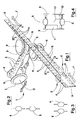
- Figure 1 schematically illustrates a cutting device 2 which cuts into half, in a longitudinal direction, a strip 3 of containers arriving from the forming station.
- the longitudinal cut separates the first, upper line of containers 4, in which the apertures are upwardly-facing, from the second, lower line of containers 5, in which the apertures are downwardly-facing.
- the first line of containers 4 proceeds, after the cut, following the advancement line normally, which brings it to the filling station, while the second line is tilted by 180° by the tiling device 1 which also aligns the second line with the first line, so that the two lines proceed parallel to one another towards the filling station, both with their apertures facing upwards in order to receive the product which is to be put into the containers.
- the tilting device 1 of the strip of containers 5 comprises three drum guides, respectively 6, 7 and 8, about which the transiting strip winds in sequence.
- Each drum guide comprises a wheel, freely rotatable about an axis thereof and laterally provided with two opposite borders 9, for laterally containing the strip.
- the strip winds about each guide with a flat side of the strip oriented parallel to the rotation axis of the guide.
- Figure 4 shows any one of the three guides, having a lateral surface which in section is conformed complementarily to the container strip.
- the lateral surface comprises at its centre a concave annular part 10, thanks to which the containers are not subject to deformation, which annular part 10 is predisposed to receive the main body of the containers; the annular part 10 may be in the shape of a continuous gullet or can be a series of recesses arranged circumferentially and equidistanced one from another at a distance which is equal to the step of the containers on the strip.
- the lateral surface of the guides further comprises two annular end surfaces 11 and 12, of unequal diameters, one of which is predisposed to receive the welded part of the strip which does not comprise a container, and the other of which is predisposed to receive the part of the strip comprising the container mouths, which terminate in the apertures.
- the mouths of the containers can be located in cavities arranged circumferentially on the annular end surface 12 of the guide at reciprocal distances equal to the step of the mouths.
- the first guide 6 is located close to the advancement line F of the strip having a winding axis perpendicular to the advancement line and arranged vertically.
- the first guide 6 causes the strip to deviate by about 90° (in the case of figure 1, towards the left) with respect to the normal line of advancement F.
- the second guide 7 which is situated by the side of and at a certain distance from the line of advancement F, exhibits a winding axis which is parallel to the line of advancement F.
- the strip in passing from the first guide 6 to the second guide 7, is twisted on itself (in the illustrated embodiment by about 90°) so that the containers pass from a vertical configuration, with the apertures facing downwards, to a horizontal configuration, with the apertures facing forwards.
- the strip exits from the second guide 7 in an opposite direction with respect to the entrance direction, after having rotated by 180° about the axis of the drum, with the containers horizontal and the apertures facing forwards.
- the third guide 8 which is located in proximity of the line of advancement F, slightly more forwards than the first guide 6, exhibits a winding axis which is perpendicular to the line of advancement.
- the third guide 8, which is very close to the first guide 6, is situated slightly higher and to the left of the first guide 6, so that the strip of containers 5 exiting from the third guide 8 comes to be side-by-side, parallel and at the same height as the other strip of containers 4 which proceeds normally along the line of advancement F, with the same orientation as before.
- the strip of containers 5 twists on itself (by about 90° in the present embodiment) so that the containers are brought from the horizontal position to a vertical configuration, with the apertures facing upwards.
- the strip of containers 5 enters the third guide 8 in a more-or-less perpendicular direction to the line of advancement F and when the strip exits from the third guide 8, after winding by about a quarter of a full turn around the vertical axis of the drum, comes to be on the line of advancement F, paired with the other strip.
- the position of the second guide 7 can be adjusted in at least one direction G transversal to the line of advancement F, so that the timing of the two paired lines of containers 4 and 5 can be adjusted on exit from the tilting device.
- the winding axes of the first guide 6 and the third guide 8 are parallel to each other and parallel to the lie (in this case vertical) of the flat part of the strip transiting along the main line of advancement F.
- the winding axis of the second guide 7 is perpendicular to the axes of the other two guides 6 and 8.
- the device 11 During operation, in a first stage, in which the device 11 is readied, the first tract of the strip of containers 5 is manually wound onto the three guides 6, 7 and 8, rotating and twisting the strip in the above-described way. Then, once the strip has been engaged on the drawing means (of known type and not illustrated), which cause the strip to advance (generally in step-motion), the device is ready to function automatically.
- the winding guides which in the illustrated embodiment comprise freely-rotatable drums or pulleys, can be constituted by fixed cylindrical elements. It is however preferable that at least the second guide 7 comprises a rotatable element 7. Further, at least one of the wheels or pulleys (preferably the second) can be a drive pulley and be provided, on its surface, with means for drawing the strip, such as for example cogs (which could be conformed similarly to the containers), or an external high-friction surface, or both solutions together.
- the change in orientation of the strip of containers 5 is made when the strip is in a transversally deviated path with respect to the main line of advancement F.
- the space occupied in a longitudinal direction (according to the main axis of advancement of the strip towards the filling station) in order to carry out the twisting operation is reduced to a minimum, indeed is practically eliminated. Even the space occupied in a transversal direction is relatively small. With this solution the forming and filling of the containers 4 and 5 occupies a relatively contained space, especially lengthwise.
- a strip of containers is tilted starting from a configuration in which the flat part of the strip is vertically arranged.
- the tilting device can however be applied in cases where the starting configuration is different, for example with the flat part horizontally arranged.
- the tilting device can also be used with strips of containers made from one film only of heat-formable plastic material (of known type).
- the containers are open trays, open on one side with the openings arranged on the flat side of the strip and turned the same way, and not, as in the previously-illustrated case, arranged on the edge of the strip and turned on opposite sides.
- the machine can comprise a heat-forming station in which, on the same strip of plastic material, two paired and symmetrical lines of containers are formed; after forming one of the two lines is tilted by 180° and superimposed on the other line. To favour tilting it is preferable first to make a longitudinal cut between the two lines.
- the tilting device and process can be applied on a machine which forms strips of containers composed of a single line of containers.
- a machine for example a forming, filling and sealing machine, can comprise one or even a plurality of tilting devices, should it be necessary to tilt the strip of containers once, twice or more times in a same machine.
Landscapes
- Engineering & Computer Science (AREA)
- Mechanical Engineering (AREA)
- Containers And Plastic Fillers For Packaging (AREA)
- Making Paper Articles (AREA)
- Auxiliary Devices For And Details Of Packaging Control (AREA)
Priority Applications (13)
| Application Number | Priority Date | Filing Date | Title |
|---|---|---|---|
| EP00830771A EP1209080A1 (de) | 2000-11-23 | 2000-11-23 | Verfahren und Vorrichtung zum Kippen einer endelosen Bahn von Behältern |
| BR0115530-0A BR0115530A (pt) | 2000-11-23 | 2001-11-07 | Processo e dispositivo para inclinar uma tira contìnua de recipientes fabricados de material conformável por aquecimento |
| US10/432,407 US20040045265A1 (en) | 2000-11-23 | 2001-11-07 | Process and device for tilting a continuous strip of containers made from heat-formable material |
| DE60134492T DE60134492D1 (de) | 2000-11-23 | 2001-11-07 | Verfahren und vorrichtung zum neigen eines kontinuierlichen behälterbands aus wärmeformbarem material |
| HK04100601.7A HK1058780B (en) | 2000-11-23 | 2001-11-07 | A process and device for tilting a continuous strip of containers made from heat-formable material |
| EP01997435A EP1341695B1 (de) | 2000-11-23 | 2001-11-07 | Verfahren und vorrichtung zum neigen eines kontinuierlichen behälterbands aus wärmeformbarem material |
| PCT/IT2001/000560 WO2002042159A1 (en) | 2000-11-23 | 2001-11-07 | A process and device for tilting a continuous strip of containers made from heat-formable material |
| CNA018193471A CN1476401A (zh) | 2000-11-23 | 2001-11-07 | 一种用来翻转连续的由热成形材料制成的容器条的方法和装置 |
| ES01997435T ES2307674T3 (es) | 2000-11-23 | 2001-11-07 | Procedimiento y dispositivo para bascular una banda continua de contenedores realizados en maerial termoconfortable. |
| JP2002544307A JP2004514603A (ja) | 2000-11-23 | 2001-11-07 | 熱成形可能な材料からなる容器を含む連続ストリップを傾けるためのプロセスおよび装置 |
| AT01997435T ATE398575T1 (de) | 2000-11-23 | 2001-11-07 | Verfahren und vorrichtung zum neigen eines kontinuierlichen behälterbands aus wärmeformbarem material |
| AU2002222510A AU2002222510A1 (en) | 2000-11-23 | 2001-11-07 | A process and device for tilting a continuous strip of containers made from heat-formable material |
| US10/973,672 US20050138902A1 (en) | 2000-11-23 | 2004-10-26 | Process and device for tilting a continuous strip of containers made from heat-formable material |
Applications Claiming Priority (1)
| Application Number | Priority Date | Filing Date | Title |
|---|---|---|---|
| EP00830771A EP1209080A1 (de) | 2000-11-23 | 2000-11-23 | Verfahren und Vorrichtung zum Kippen einer endelosen Bahn von Behältern |
Publications (1)
| Publication Number | Publication Date |
|---|---|
| EP1209080A1 true EP1209080A1 (de) | 2002-05-29 |
Family
ID=8175562
Family Applications (2)
| Application Number | Title | Priority Date | Filing Date |
|---|---|---|---|
| EP00830771A Withdrawn EP1209080A1 (de) | 2000-11-23 | 2000-11-23 | Verfahren und Vorrichtung zum Kippen einer endelosen Bahn von Behältern |
| EP01997435A Expired - Lifetime EP1341695B1 (de) | 2000-11-23 | 2001-11-07 | Verfahren und vorrichtung zum neigen eines kontinuierlichen behälterbands aus wärmeformbarem material |
Family Applications After (1)
| Application Number | Title | Priority Date | Filing Date |
|---|---|---|---|
| EP01997435A Expired - Lifetime EP1341695B1 (de) | 2000-11-23 | 2001-11-07 | Verfahren und vorrichtung zum neigen eines kontinuierlichen behälterbands aus wärmeformbarem material |
Country Status (10)
| Country | Link |
|---|---|
| US (2) | US20040045265A1 (de) |
| EP (2) | EP1209080A1 (de) |
| JP (1) | JP2004514603A (de) |
| CN (1) | CN1476401A (de) |
| AT (1) | ATE398575T1 (de) |
| AU (1) | AU2002222510A1 (de) |
| BR (1) | BR0115530A (de) |
| DE (1) | DE60134492D1 (de) |
| ES (1) | ES2307674T3 (de) |
| WO (1) | WO2002042159A1 (de) |
Families Citing this family (12)
| Publication number | Priority date | Publication date | Assignee | Title |
|---|---|---|---|---|
| US20060277555A1 (en) * | 2005-06-03 | 2006-12-07 | Damian Howard | Portable device interfacing |
| US20080147321A1 (en) * | 2006-12-18 | 2008-06-19 | Damian Howard | Integrating Navigation Systems |
| US20080215240A1 (en) * | 2006-12-18 | 2008-09-04 | Damian Howard | Integrating User Interfaces |
| US20080147308A1 (en) * | 2006-12-18 | 2008-06-19 | Damian Howard | Integrating Navigation Systems |
| US7931505B2 (en) * | 2007-11-15 | 2011-04-26 | Bose Corporation | Portable device interfacing |
| US9487348B2 (en) | 2015-03-20 | 2016-11-08 | Meltz, LLC | Systems for and methods of providing support for displaceable frozen contents in beverage and food receptacles |
| US10111554B2 (en) | 2015-03-20 | 2018-10-30 | Meltz, LLC | Systems for and methods of controlled liquid food or beverage product creation |
| US10314320B2 (en) | 2015-03-20 | 2019-06-11 | Meltz, LLC | Systems for controlled liquid food or beverage product creation |
| US9346611B1 (en) | 2015-03-20 | 2016-05-24 | Meltz, LLC | Apparatus and processes for creating a consumable liquid food or beverage product from frozen contents |
| CA3047813A1 (en) | 2017-01-04 | 2018-07-12 | Church & Dwight Co., Inc. | A system and a related method for forming a multi-chamber package |
| MX2019012834A (es) | 2017-04-27 | 2019-12-16 | Meltz Llc | Metodo para extraccion centrifuga y aparato adecuado para llevar a cabo este metodo. |
| US11724849B2 (en) | 2019-06-07 | 2023-08-15 | Cometeer, Inc. | Packaging and method for single serve beverage product |
Citations (3)
| Publication number | Priority date | Publication date | Assignee | Title |
|---|---|---|---|---|
| US2544020A (en) * | 1948-09-03 | 1951-03-06 | Roderick W Hoag | Method and machine for making and filling fluted containers |
| US3782066A (en) * | 1971-04-26 | 1974-01-01 | Ind Werke Karlsruke Augsburg A | Method of making and filling an aseptic packing container |
| US4907394A (en) * | 1988-05-27 | 1990-03-13 | Unionpack Industrielle Lohnverpackuns-Gmbh & Co. | Method for producing a foil-container, apparatus for the implementation of the said method, and a foil-container produced according to the said method |
Family Cites Families (15)
| Publication number | Priority date | Publication date | Assignee | Title |
|---|---|---|---|---|
| US3348905A (en) * | 1967-10-24 | Method for sterilization of an ointment impregnated gauze | ||
| US2918168A (en) * | 1954-10-15 | 1959-12-22 | Gen Packets Inc | Shaker dispenser packet |
| US3273300A (en) * | 1963-08-07 | 1966-09-20 | Procter & Gamble | Continuous dough cutting and packaging |
| US3309037A (en) * | 1964-10-08 | 1967-03-14 | Du Pont | Web rewinder |
| US3399884A (en) * | 1966-03-15 | 1968-09-03 | Procter & Gamble | Method and apparatus for combining webs |
| US3735767A (en) * | 1970-10-20 | 1973-05-29 | Hauni Werke Koerber & Co Kg | Method and machine for the making of cigarette packs or the like |
| BE794176A (fr) * | 1972-01-17 | 1973-05-16 | Fmc Corp | Dispositif de devers automatique pour machine de remplissage tournante |
| US4224781A (en) * | 1979-01-18 | 1980-09-30 | Sundpacma Aktiebolag | Apparatus for handling of unsealed slit boxes |
| US4375146A (en) * | 1979-06-11 | 1983-03-01 | International Automated Machinery, Inc. | Continuous rotary machine and method for forming, filling, and sealing package of laminated sheet material |
| DE3067590D1 (en) * | 1980-01-02 | 1984-05-24 | Agfa Gevaert Nv | Web controlling apparatus |
| NL8401835A (nl) * | 1984-06-08 | 1986-01-02 | Thomassen & Drijver | Werkwijze en inrichting voor het vervaardigen van een van een vulling voorzien blik, een werkwijze voor het vervaardigen van dit blik, en een volgens een werkwijze vervaardigd blik, blikdeel en/of eindwand. |
| US5092573A (en) * | 1990-09-05 | 1992-03-03 | Abreu Michael L | Auxiliary paper feeding apparatus for high speed computer printers |
| DE4313434A1 (de) * | 1993-04-27 | 1994-11-03 | Focke & Co | Verfahren und Vorrichtung zum Einführen von Zigarettten oder dergleichen in Verpackungen |
| US5765345A (en) * | 1993-09-29 | 1998-06-16 | Ivers-Lee Corporation | Deep draw package and system for making same, including apparatus and method |
| US5466321A (en) * | 1993-12-17 | 1995-11-14 | Sanki Machinery Co., Ltd. | Method of and apparatus for superposing strip members |
-
2000
- 2000-11-23 EP EP00830771A patent/EP1209080A1/de not_active Withdrawn
-
2001
- 2001-11-07 BR BR0115530-0A patent/BR0115530A/pt not_active IP Right Cessation
- 2001-11-07 CN CNA018193471A patent/CN1476401A/zh active Pending
- 2001-11-07 EP EP01997435A patent/EP1341695B1/de not_active Expired - Lifetime
- 2001-11-07 AT AT01997435T patent/ATE398575T1/de active
- 2001-11-07 JP JP2002544307A patent/JP2004514603A/ja active Pending
- 2001-11-07 AU AU2002222510A patent/AU2002222510A1/en not_active Abandoned
- 2001-11-07 DE DE60134492T patent/DE60134492D1/de not_active Expired - Lifetime
- 2001-11-07 WO PCT/IT2001/000560 patent/WO2002042159A1/en not_active Ceased
- 2001-11-07 ES ES01997435T patent/ES2307674T3/es not_active Expired - Lifetime
- 2001-11-07 US US10/432,407 patent/US20040045265A1/en not_active Abandoned
-
2004
- 2004-10-26 US US10/973,672 patent/US20050138902A1/en not_active Abandoned
Patent Citations (3)
| Publication number | Priority date | Publication date | Assignee | Title |
|---|---|---|---|---|
| US2544020A (en) * | 1948-09-03 | 1951-03-06 | Roderick W Hoag | Method and machine for making and filling fluted containers |
| US3782066A (en) * | 1971-04-26 | 1974-01-01 | Ind Werke Karlsruke Augsburg A | Method of making and filling an aseptic packing container |
| US4907394A (en) * | 1988-05-27 | 1990-03-13 | Unionpack Industrielle Lohnverpackuns-Gmbh & Co. | Method for producing a foil-container, apparatus for the implementation of the said method, and a foil-container produced according to the said method |
Also Published As
| Publication number | Publication date |
|---|---|
| HK1058780A1 (en) | 2004-06-04 |
| JP2004514603A (ja) | 2004-05-20 |
| AU2002222510A1 (en) | 2002-06-03 |
| ES2307674T3 (es) | 2008-12-01 |
| EP1341695A1 (de) | 2003-09-10 |
| US20040045265A1 (en) | 2004-03-11 |
| ATE398575T1 (de) | 2008-07-15 |
| WO2002042159A1 (en) | 2002-05-30 |
| DE60134492D1 (de) | 2008-07-31 |
| EP1341695B1 (de) | 2008-06-18 |
| US20050138902A1 (en) | 2005-06-30 |
| CN1476401A (zh) | 2004-02-18 |
| BR0115530A (pt) | 2004-07-06 |
Similar Documents
| Publication | Publication Date | Title |
|---|---|---|
| EP1341695B1 (de) | Verfahren und vorrichtung zum neigen eines kontinuierlichen behälterbands aus wärmeformbarem material | |
| US4002005A (en) | Package of nested containers and method and apparatus for producing same | |
| ITTO950211A1 (it) | Dispositivo per la termosigillatura in continuo di involucri di confe zionamento di materiale polimerico termosaldabile e macchine perfezio | |
| ITBO960574A1 (it) | Metodo ed unita' per la formazione di gruppi di prodotti | |
| CN105579346B (zh) | 用于将产品包装于由外体及内袋构成的容器中的装置及方法 | |
| CN105151360A (zh) | 四边封包装机 | |
| US20170107007A1 (en) | Tight seal system for the packaging of products | |
| KR101205235B1 (ko) | 횡형 손잡이 홀 가공이 가능한 음료용기용 횡형 자동 포장기 | |
| HK1058780B (en) | A process and device for tilting a continuous strip of containers made from heat-formable material | |
| EP2097322B1 (de) | Behälter, gerät und verfahren zur herstellung eines behälters | |
| US20040079051A1 (en) | Semi-automatic vial closing apparatus | |
| US4663916A (en) | Apparatus for forming, welding and conveying packs | |
| CN1480318B (zh) | 一种制造整套成型不损坏模型的罐体的方法和机器 | |
| US11840364B2 (en) | Packaging machine for packaging portioned products which are liquid or pasty in the processing state | |
| CN102991738A (zh) | 砖包灌装机的砖包成型装置 | |
| CN202828123U (zh) | 砖包灌装机的砖包成型装置 | |
| IT201800000927A1 (it) | Dispositivo e metodo di applicazione di uno spezzone di film di materiale ad un contenitore | |
| CN114684426B (zh) | 纸制品自动化包装装置 | |
| JPH0133441Y2 (de) | ||
| US20070137143A1 (en) | Machine for the production of groups of roll products | |
| US5210995A (en) | Machine designed for packaging objects, particularly containers | |
| CN110576640B (zh) | 用于形成具有侧部角撑板的柔性材料的包装的方法和机器 | |
| US4519282A (en) | Method for boxing bubble strips | |
| CN119503227A (zh) | 一种合并输送装置 | |
| JP2012062073A (ja) | スティック型包装袋製造用の充填包装機及びスティック型包装袋の製造方法 |
Legal Events
| Date | Code | Title | Description |
|---|---|---|---|
| PUAI | Public reference made under article 153(3) epc to a published international application that has entered the european phase |
Free format text: ORIGINAL CODE: 0009012 |
|
| AK | Designated contracting states |
Kind code of ref document: A1 Designated state(s): AT BE CH CY DE DK ES FI FR GB GR IE IT LI LU MC NL PT SE TR |
|
| AX | Request for extension of the european patent |
Free format text: AL;LT;LV;MK;RO;SI |
|
| AKX | Designation fees paid | ||
| REG | Reference to a national code |
Ref country code: DE Ref legal event code: 8566 |
|
| STAA | Information on the status of an ep patent application or granted ep patent |
Free format text: STATUS: THE APPLICATION IS DEEMED TO BE WITHDRAWN |
|
| 18D | Application deemed to be withdrawn |
Effective date: 20021130 |