EP1208732B2 - Ölsammelflasche - Google Patents
Ölsammelflasche Download PDFInfo
- Publication number
- EP1208732B2 EP1208732B2 EP01204280A EP01204280A EP1208732B2 EP 1208732 B2 EP1208732 B2 EP 1208732B2 EP 01204280 A EP01204280 A EP 01204280A EP 01204280 A EP01204280 A EP 01204280A EP 1208732 B2 EP1208732 B2 EP 1208732B2
- Authority
- EP
- European Patent Office
- Prior art keywords
- bottle
- valves
- oil
- vehicle
- valve
- Prior art date
- Legal status (The legal status is an assumption and is not a legal conclusion. Google has not performed a legal analysis and makes no representation as to the accuracy of the status listed.)
- Expired - Lifetime
Links
Images


Classifications
-
- A—HUMAN NECESSITIES
- A01—AGRICULTURE; FORESTRY; ANIMAL HUSBANDRY; HUNTING; TRAPPING; FISHING
- A01B—SOIL WORKING IN AGRICULTURE OR FORESTRY; PARTS, DETAILS, OR ACCESSORIES OF AGRICULTURAL MACHINES OR IMPLEMENTS, IN GENERAL
- A01B71/00—Construction or arrangement of setting or adjusting mechanisms, of implement or tool drive or of power take-off; Means for protecting parts against dust, or the like; Adapting machine elements to or for agricultural purposes
- A01B71/08—Means for protecting against dust or the like, or for cleaning agricultural implements
Definitions
- the present invention relates to an oil reclaim bottle for use on an agricultural vehicle to prevent oil spillage from a hydraulic valve that is provided on the vehicle for connection to external accessories.
- Agricultural vehicles such as tractors and combine harvesters, are often designed to drive accessories hydraulically and to this end they are provided with valves to which hydraulic hoses of the accessories can be connected.
- valves to which hydraulic hoses of the accessories can be connected.
- the above solution has the disadvantage that it requires several components leading to increased assembly time and moreover is prone to interference with moving parts, such as a three point hitch, especially when installed at the back of a tractor.
- an oil reclaim bottle as claimed for use on an agricultural vehicle to prevent oil spillage from a hydraulic valve that is provided on the vehicle for connection to external accessories.
- valves arranged in groups of four (or even more), each group consisting of two pairs of vertically spaced valves with the pairs spaced horizontally from one another.
- the bottle may have two horizontally spaced openings each receiving oil drips from a respective one of the pairs of valves.
- the mounting means may simply comprise a clamping bolt projecting upwards from the bottle between the two pairs of valves into a transverse yoke located above and straddling the two pairs of valves.
- the bottle may be constructed of sheet metal but it is preferred for it to be formed of a plastics material such as polyethylene or polypropylene.
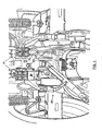
- FIG. 1 shows the rear end of a tractor having hydraulic valves for driving accessories (not shown) which are arranged in two groups 10 of four valves.
- Each group 10 comprises two pairs of valves 12, 14 for driving two accessories.
- the valves are in pairs because, at any one time, one valve will act as a supply valve to the driven accessory and the other as a return valve.
- the two valves constituting each of the pair of valves 12 or 14 connected to the same accessory are arranged one above the other and their connector housings 16 communicate with one another so that escaping oil from either valve in the pair drips out of the connector housing 16 of the lower valve.
- FIG. 1 The conventional arrangement of a reclaim bottle is shown in Figure 1 fitted to the right hand group of valves.
- Flexible tubes 18 which are connected to the lower valve connector housing 16 in each pair are joined by means of a Y-shaped coupling to a common tube 22 which leads to a bottle 24 located remotely from the valves.
- a special bracket has to be provided on the vehicle to act as a receptacle for the reclaim bottle 24.
- the bottle 30 of the preferred embodiment of the invention shown on the left hand side in Figure 1 and to an enlarged scale in Figure 2 , comprises a plastics bottle 30 that is mounted immediately below the valves 12 and 14 to receive any drip directly.
- the bottle 30 is a plastics container with a removable cap 32.
- the cap is provided to allow the contents of the bottle to be emptied when the reclaimed oil reaches its full capacity.
- the top surface 34 of the bottle 30 is formed with two openings 36 and 38 that lie beneath the valve connector housings 16 to receive oil drips.
- the bottle 30 is held in place by means of a bolt 40 that passes between the two pairs of valves 12 and 14 and through a yoke 42 fitted over the two upper valves. Tightening of an internally threaded hand wheel 44 that engages the bolt 40 clamps the bottle 30 beneath the valves and maintains the openings 36 and 38 in sealing engagement with the lower valves of the group.
- the described preferred embodiment of the invention offers the advantages of using fewer components, in that it dispenses with the flexible tubes 18 and 22, the Y-shaped coupling 20 and the bracket for receiving the bottle 24.
- the bottle is quicker to assemble as it can be offered up to the valves from beneath and then mounted in position by simply slipping the yoke 42 over the end of the bolt 40 and tightening the hand wheel 42, the entire operation requiring no tools.
- the risk of leakage is reduced because there are no tubes that can be damaged or that can come loose.
- the bottle is mounted in a readily accessible space immediately beneath the valves, it does not reduce the clearance for any of the moving components of the vehicle, in particular the pick-up hitch linkage which is designated 50 in Figure 1 .
- the single bottle 30 has been replaced by two separate bottles 46, each associated with a respective pair of vertically arranged valves.
- Each bottle 46 has a removable cap 47 provided at a lower part of the rearwardly facing side of the bottle enabling the bottle to be emptied on a timely basis without having to remove the bottle from the valve block.
- the bottle 46 could be provided with a bottom wall sloping downwardly towards the cap 47.
- Each bottle 46 is attached to its respective pair of valves by means of a single-use plastic strap 48.
- the strap 48 also could be cut and replaced by a new strap when refitting the bottle 46.
- valves are not limited for use to the design of the valves as shown in the drawings. Instead of two valves provided one above the other, also four or even more valves could be provided in a vertically arranged stack. It furthermore is not required for the valves provided in one vertical plane to be horizontally co-planer with the valves in the adjacent other vertical plane. The valves of adjacent vertical planes indeed may be staggered resulting in the lower valves of the vertical stacks being provided at different horizontal levels. This design allows the valve stacks to be fitted closer to each other thereby reducing the overall transverse dimension. The solution with the separate bottles 46 easily could be applied to the latter design as the vertical positions of the bottles 46 are independent from one another.
- the bottle should be provided with a longitudinally provided step in its upper surface such that one of the openings 36, 38 is provided at a different horizontal level than the other opening, each opening again sealingly engaging its associated valve.
- the present invention is also applicable to a single valve or a pair of valves, either arranged vertically above one another or horizontally next to each other.
Landscapes
- Life Sciences & Earth Sciences (AREA)
- Engineering & Computer Science (AREA)
- Mechanical Engineering (AREA)
- Soil Sciences (AREA)
- Environmental Sciences (AREA)
- Lubrication Details And Ventilation Of Internal Combustion Engines (AREA)
- Details Of Rigid Or Semi-Rigid Containers (AREA)
- Loading And Unloading Of Fuel Tanks Or Ships (AREA)
- Lubricants (AREA)
- Fats And Perfumes (AREA)
Claims (9)
- Ölsammelflasche zur Verwendung auf einem landwirtschaftlichen Fahrzeug zum Verhindern eines Auslaufens von Öl von einem Hydraulik-Ventil (12, 14), das auf dem Fahrzeug zur Verbindung mit externen Zusatzgeräten vorgesehen ist, und
dadurch gekennzeichnet, dass die Flasche (30/46) so geformt ist, dass sie unmittelbar unter das Hydraulik-Ventil passt und Befestigungseinrichtungen (40, 42, 44/48) aufweist, die es ermöglichen, dass die Flasche auf dem Fahrzeug unmittelbar unterhalb des Hydraulik-Ventils (12, 14) befestigt werden kann und die betreibbar sind, um die Flasche (30/46) direkt an dem Ventil (12, 14) zu befestigen, wobei die Flasche (30/46) zumindest eine Öffnung (36, 38) in ihrer oberen Oberfläche (34) aufweist, durch die hindurch Öltropfen von dem Ventil (12, 14) direkt in die Flasche (30, 46) eintreten können, und dass bei der Befestigung auf dem Fahrzeug die zumindest eine Öffnung (36, 38) in der oberen Oberfläche (34) der Flasche (30/46) durch das Ventil (12, 14) verschlossen und abgedichtet ist. - Ölsammelflasche nach Anspruch 1, dadurch gekennzeichnet, dass die Flasche (30/46) mit einer abnehmbaren Kappe (32/47) zum Entleeren der Flasche versehen ist.
- Ölsammelflasche nach einem der vorhergehenden Ansprüche, dadurch gekennzeichnet, dass die Flasche (30) zur Verwendung in einem Fahrzeug vorgesehen ist, das Ventile (12, 14) aufweist, die in Gruppen von zumindest vier Ventilen angeordnet sind, wobei jede Gruppe aus zwei Paaren von mit vertikalem Abstand angeordneten Ventilen besteht, wobei die Paare in Horizontalrichtung mit Abstand voneinander angeordnet sind, wobei die Flasche zwei mit horizontalem Abstand angeordnete Öffnungen (36, 38) aufweist, die jeweils Öltropfen von einem jeweiligen einen Ventil der Paare von Ventilen empfangen.
- Ölsammelflasche nach Anspruch 3, dadurch gekennzeichnet, dass die Befestigungseinrichtungen eine Klemmschraube (40) umfassen, die von der Flasche (30) zwischen den zwei Paaren von Ventilen (12, 14) nach oben in ein Querjoch (42) vorspringt, das sich oberhalb der zwei Paare von Ventilen befindet und diese überquert.
- Ölsammelflasche nach Anspruch 2, dadurch gekennzeichnet, dass die Flasche (46) zur Verwendung in einem Fahrzeug vorgesehen ist, das in vertikal angeordneten Stapeln angeordnete Ventile (12, 14) aufweist, wobei jeder Stapel eine daran befestigte getrennte Flasche (46) aufweist.
- Ölsammelflasche nach Anspruch 5, dadurch gekennzeichnet, dass jede Flasche (46) an ihrem zugehörigen Stapel von Ventilen mit Hilfe eines entfernbaren Binders (48) befestigt ist.
- Ölsammelflasche nach Anspruch 6, dadurch gekennzeichnet, dass der Binder (48) ein für eine einmalige Verwendung bestimmter Kunststoffbinder ist.
- Ölsammelflasche nach Anspruch 2 und einem der darauf zurückbezogenen Ansprüche, dadurch gekennzeichnet, dass die Bodenwand der Flasche (30/46) nach unten hin in Richtung auf die abnehmbare Kappe (32/47) geneigt ist.
- Ölsammelflasche nach einem der vorhergehenden Ansprüche, dadurch gekennzeichnet, dass die Flasche (30/46) aus einem geformten Kunststoffmaterial gebildet ist.
Applications Claiming Priority (2)
| Application Number | Priority Date | Filing Date | Title |
|---|---|---|---|
| GBGB0027943.0A GB0027943D0 (en) | 2000-11-16 | 2000-11-16 | Oil reclaim bottle |
| GB0027943 | 2000-11-16 |
Publications (3)
| Publication Number | Publication Date |
|---|---|
| EP1208732A1 EP1208732A1 (de) | 2002-05-29 |
| EP1208732B1 EP1208732B1 (de) | 2005-11-09 |
| EP1208732B2 true EP1208732B2 (de) | 2009-10-07 |
Family
ID=9903269
Family Applications (1)
| Application Number | Title | Priority Date | Filing Date |
|---|---|---|---|
| EP01204280A Expired - Lifetime EP1208732B2 (de) | 2000-11-16 | 2001-11-09 | Ölsammelflasche |
Country Status (4)
| Country | Link |
|---|---|
| EP (1) | EP1208732B2 (de) |
| AT (1) | ATE308873T1 (de) |
| DE (1) | DE60114749T3 (de) |
| GB (1) | GB0027943D0 (de) |
Family Cites Families (2)
| Publication number | Priority date | Publication date | Assignee | Title |
|---|---|---|---|---|
| US2797957A (en) * | 1953-12-31 | 1957-07-02 | Albert L North | Combined auxiliary platform and tool cabinet for tractors |
| DE2725058A1 (de) * | 1977-06-03 | 1978-12-14 | Kloeckner Humboldt Deutz Ag | Loesbare schlauchkupplung |
-
2000
- 2000-11-16 GB GBGB0027943.0A patent/GB0027943D0/en not_active Ceased
-
2001
- 2001-11-09 AT AT01204280T patent/ATE308873T1/de active
- 2001-11-09 EP EP01204280A patent/EP1208732B2/de not_active Expired - Lifetime
- 2001-11-09 DE DE60114749T patent/DE60114749T3/de not_active Expired - Lifetime
Non-Patent Citations (3)
| Title |
|---|
| "Extract of online component parts catalogue", CLAAS METADOC FÜR ATLES 935 RZ † |
| PHOTOSERIES ATLES 935 RZ † |
| PROSPEKT ATLES 935 RZ, 1 October 2000 (2000-10-01) † |
Also Published As
| Publication number | Publication date |
|---|---|
| DE60114749T2 (de) | 2006-06-01 |
| ATE308873T1 (de) | 2005-11-15 |
| DE60114749T3 (de) | 2010-01-07 |
| EP1208732B1 (de) | 2005-11-09 |
| EP1208732A1 (de) | 2002-05-29 |
| DE60114749D1 (de) | 2005-12-15 |
| GB0027943D0 (en) | 2001-01-03 |
Similar Documents
| Publication | Publication Date | Title |
|---|---|---|
| CA3150378A1 (en) | ALL-TERRAIN VEHICLE | |
| US20130284747A1 (en) | Fluid tank and mounting configuration | |
| EP1208732B2 (de) | Ölsammelflasche | |
| US4903469A (en) | Lawn mower | |
| JPH06191297A (ja) | 産業車両用オイルタンク及びオイルタンクの取付構造 | |
| EP0202037B1 (de) | Tank für Flüssigkeiten | |
| CN218320495U (zh) | 一种具有卸荷控制组件的卧顶 | |
| US5261700A (en) | Fuel tank assembly for a vehicle | |
| JP2001025312A (ja) | 田植機 | |
| US6401770B1 (en) | Drainage diverter for vehicle waste fluids | |
| EP0515735B1 (de) | Kraftstofftankanordnung für ein Fahrzeug | |
| CN223658106U (zh) | 一种带储物装置及加热的水箱 | |
| CA2457641C (en) | Truck tank for accommodating a bed-mounted hitch | |
| EP1420223B1 (de) | Ein Kühler für Kraftfahrzeuge mit in einem Leitungstank integrierten Rohrleitungen | |
| US6851588B2 (en) | Apparatus and methods for converting the load compartment of a vehicle into a water tank | |
| EP1714819A1 (de) | Kraftstoffbehälteranlage mit zwei nebeneinander liegenden Kraftstoffbehältern | |
| GB2272880A (en) | Fluid displacement device and standpipe for automatic fluid communication | |
| JPS621324Y2 (de) | ||
| EP3821695B1 (de) | Nutzfahrzeug | |
| JP7763644B2 (ja) | 車両前部構造 | |
| CN216584186U (zh) | 一种双仓带自吸回罐和防溢功能的油罐车油路系统 | |
| US5540327A (en) | Antifreeze/coolant replacement kit | |
| JP4617201B2 (ja) | 移動農機 | |
| JPH04140203A (ja) | 塵芥収集車における汚水回収装置 | |
| JP3471631B2 (ja) | 自動車の液体交換システム |
Legal Events
| Date | Code | Title | Description |
|---|---|---|---|
| PUAI | Public reference made under article 153(3) epc to a published international application that has entered the european phase |
Free format text: ORIGINAL CODE: 0009012 |
|
| AK | Designated contracting states |
Kind code of ref document: A1 Designated state(s): AT BE CH CY DE DK ES FI FR GB GR IE IT LI LU MC NL PT SE TR |
|
| AX | Request for extension of the european patent |
Free format text: AL;LT;LV;MK;RO;SI |
|
| RAP1 | Party data changed (applicant data changed or rights of an application transferred) |
Owner name: CNH U.K. LIMITED |
|
| 17P | Request for examination filed |
Effective date: 20021121 |
|
| AKX | Designation fees paid |
Designated state(s): AT BE CH CY DE DK ES FI FR GB GR IE IT LI LU MC NL PT SE TR |
|
| GRAP | Despatch of communication of intention to grant a patent |
Free format text: ORIGINAL CODE: EPIDOSNIGR1 |
|
| GRAS | Grant fee paid |
Free format text: ORIGINAL CODE: EPIDOSNIGR3 |
|
| GRAA | (expected) grant |
Free format text: ORIGINAL CODE: 0009210 |
|
| AK | Designated contracting states |
Kind code of ref document: B1 Designated state(s): AT BE CH CY DE DK ES FI FR GB GR IE IT LI LU MC NL PT SE TR |
|
| PG25 | Lapsed in a contracting state [announced via postgrant information from national office to epo] |
Ref country code: NL Free format text: LAPSE BECAUSE OF FAILURE TO SUBMIT A TRANSLATION OF THE DESCRIPTION OR TO PAY THE FEE WITHIN THE PRESCRIBED TIME-LIMIT Effective date: 20051109 Ref country code: CY Free format text: LAPSE BECAUSE OF FAILURE TO SUBMIT A TRANSLATION OF THE DESCRIPTION OR TO PAY THE FEE WITHIN THE PRESCRIBED TIME-LIMIT Effective date: 20051109 Ref country code: CH Free format text: LAPSE BECAUSE OF FAILURE TO SUBMIT A TRANSLATION OF THE DESCRIPTION OR TO PAY THE FEE WITHIN THE PRESCRIBED TIME-LIMIT Effective date: 20051109 Ref country code: TR Free format text: LAPSE BECAUSE OF FAILURE TO SUBMIT A TRANSLATION OF THE DESCRIPTION OR TO PAY THE FEE WITHIN THE PRESCRIBED TIME-LIMIT Effective date: 20051109 Ref country code: BE Free format text: LAPSE BECAUSE OF FAILURE TO SUBMIT A TRANSLATION OF THE DESCRIPTION OR TO PAY THE FEE WITHIN THE PRESCRIBED TIME-LIMIT Effective date: 20051109 Ref country code: LI Free format text: LAPSE BECAUSE OF FAILURE TO SUBMIT A TRANSLATION OF THE DESCRIPTION OR TO PAY THE FEE WITHIN THE PRESCRIBED TIME-LIMIT Effective date: 20051109 Ref country code: IE Free format text: LAPSE BECAUSE OF NON-PAYMENT OF DUE FEES Effective date: 20051109 |
|
| REG | Reference to a national code |
Ref country code: GB Ref legal event code: FG4D |
|
| REG | Reference to a national code |
Ref country code: CH Ref legal event code: EP |
|
| PG25 | Lapsed in a contracting state [announced via postgrant information from national office to epo] |
Ref country code: MC Free format text: LAPSE BECAUSE OF NON-PAYMENT OF DUE FEES Effective date: 20051130 |
|
| REG | Reference to a national code |
Ref country code: IE Ref legal event code: FG4D |
|
| REF | Corresponds to: |
Ref document number: 60114749 Country of ref document: DE Date of ref document: 20051215 Kind code of ref document: P |
|
| PG25 | Lapsed in a contracting state [announced via postgrant information from national office to epo] |
Ref country code: LU Free format text: LAPSE BECAUSE OF NON-PAYMENT OF DUE FEES Effective date: 20060109 |
|
| PG25 | Lapsed in a contracting state [announced via postgrant information from national office to epo] |
Ref country code: SE Free format text: LAPSE BECAUSE OF FAILURE TO SUBMIT A TRANSLATION OF THE DESCRIPTION OR TO PAY THE FEE WITHIN THE PRESCRIBED TIME-LIMIT Effective date: 20060209 Ref country code: DK Free format text: LAPSE BECAUSE OF FAILURE TO SUBMIT A TRANSLATION OF THE DESCRIPTION OR TO PAY THE FEE WITHIN THE PRESCRIBED TIME-LIMIT Effective date: 20060209 Ref country code: GR Free format text: LAPSE BECAUSE OF FAILURE TO SUBMIT A TRANSLATION OF THE DESCRIPTION OR TO PAY THE FEE WITHIN THE PRESCRIBED TIME-LIMIT Effective date: 20060209 |
|
| PG25 | Lapsed in a contracting state [announced via postgrant information from national office to epo] |
Ref country code: ES Free format text: LAPSE BECAUSE OF FAILURE TO SUBMIT A TRANSLATION OF THE DESCRIPTION OR TO PAY THE FEE WITHIN THE PRESCRIBED TIME-LIMIT Effective date: 20060220 |
|
| PG25 | Lapsed in a contracting state [announced via postgrant information from national office to epo] |
Ref country code: PT Free format text: LAPSE BECAUSE OF FAILURE TO SUBMIT A TRANSLATION OF THE DESCRIPTION OR TO PAY THE FEE WITHIN THE PRESCRIBED TIME-LIMIT Effective date: 20060410 |
|
| NLV1 | Nl: lapsed or annulled due to failure to fulfill the requirements of art. 29p and 29m of the patents act | ||
| REG | Reference to a national code |
Ref country code: CH Ref legal event code: PL |
|
| ET | Fr: translation filed | ||
| PLBI | Opposition filed |
Free format text: ORIGINAL CODE: 0009260 |
|
| REG | Reference to a national code |
Ref country code: IE Ref legal event code: MM4A |
|
| PLAX | Notice of opposition and request to file observation + time limit sent |
Free format text: ORIGINAL CODE: EPIDOSNOBS2 |
|
| 26 | Opposition filed |
Opponent name: CLAAS KGAA MBH Effective date: 20060808 |
|
| PLBB | Reply of patent proprietor to notice(s) of opposition received |
Free format text: ORIGINAL CODE: EPIDOSNOBS3 |
|
| PUAH | Patent maintained in amended form |
Free format text: ORIGINAL CODE: 0009272 |
|
| STAA | Information on the status of an ep patent application or granted ep patent |
Free format text: STATUS: PATENT MAINTAINED AS AMENDED |
|
| 27A | Patent maintained in amended form |
Effective date: 20091007 |
|
| AK | Designated contracting states |
Kind code of ref document: B2 Designated state(s): AT BE CH CY DE DK ES FI FR GB GR IE IT LI LU MC NL PT SE TR |
|
| REG | Reference to a national code |
Ref country code: ES Ref legal event code: FD2A Effective date: 20061110 |
|
| PGFP | Annual fee paid to national office [announced via postgrant information from national office to epo] |
Ref country code: AT Payment date: 20141126 Year of fee payment: 14 |
|
| REG | Reference to a national code |
Ref country code: FR Ref legal event code: PLFP Year of fee payment: 15 |
|
| REG | Reference to a national code |
Ref country code: AT Ref legal event code: MM01 Ref document number: 308873 Country of ref document: AT Kind code of ref document: T Effective date: 20151109 |
|
| PG25 | Lapsed in a contracting state [announced via postgrant information from national office to epo] |
Ref country code: AT Free format text: LAPSE BECAUSE OF NON-PAYMENT OF DUE FEES Effective date: 20151109 |
|
| REG | Reference to a national code |
Ref country code: FR Ref legal event code: PLFP Year of fee payment: 16 |
|
| REG | Reference to a national code |
Ref country code: FR Ref legal event code: PLFP Year of fee payment: 17 |
|
| PGFP | Annual fee paid to national office [announced via postgrant information from national office to epo] |
Ref country code: FI Payment date: 20171122 Year of fee payment: 17 |
|
| REG | Reference to a national code |
Ref country code: FR Ref legal event code: PLFP Year of fee payment: 18 |
|
| PG25 | Lapsed in a contracting state [announced via postgrant information from national office to epo] |
Ref country code: FI Free format text: LAPSE BECAUSE OF NON-PAYMENT OF DUE FEES Effective date: 20181109 |
|
| PGFP | Annual fee paid to national office [announced via postgrant information from national office to epo] |
Ref country code: DE Payment date: 20191128 Year of fee payment: 19 |
|
| PGFP | Annual fee paid to national office [announced via postgrant information from national office to epo] |
Ref country code: FR Payment date: 20191124 Year of fee payment: 19 |
|
| PGFP | Annual fee paid to national office [announced via postgrant information from national office to epo] |
Ref country code: GB Payment date: 20191122 Year of fee payment: 19 |
|
| PG25 | Lapsed in a contracting state [announced via postgrant information from national office to epo] |
Ref country code: IT Free format text: LAPSE BECAUSE OF NON-PAYMENT OF DUE FEES Effective date: 20191109 |
|
| REG | Reference to a national code |
Ref country code: DE Ref legal event code: R119 Ref document number: 60114749 Country of ref document: DE |
|
| REG | Reference to a national code |
Ref country code: DE Ref legal event code: R082 Ref document number: 60114749 Country of ref document: DE Representative=s name: MEISSNER BOLTE PATENTANWAELTE RECHTSANWAELTE P, DE |
|
| GBPC | Gb: european patent ceased through non-payment of renewal fee |
Effective date: 20201109 |
|
| PG25 | Lapsed in a contracting state [announced via postgrant information from national office to epo] |
Ref country code: FR Free format text: LAPSE BECAUSE OF NON-PAYMENT OF DUE FEES Effective date: 20201130 |
|
| PG25 | Lapsed in a contracting state [announced via postgrant information from national office to epo] |
Ref country code: GB Free format text: LAPSE BECAUSE OF NON-PAYMENT OF DUE FEES Effective date: 20201109 Ref country code: DE Free format text: LAPSE BECAUSE OF NON-PAYMENT OF DUE FEES Effective date: 20210601 |