EP1207598A2 - Laser à semi-conducteur à émission de surface - Google Patents
Laser à semi-conducteur à émission de surface Download PDFInfo
- Publication number
- EP1207598A2 EP1207598A2 EP01126412A EP01126412A EP1207598A2 EP 1207598 A2 EP1207598 A2 EP 1207598A2 EP 01126412 A EP01126412 A EP 01126412A EP 01126412 A EP01126412 A EP 01126412A EP 1207598 A2 EP1207598 A2 EP 1207598A2
- Authority
- EP
- European Patent Office
- Prior art keywords
- layer
- semiconductor laser
- surface emitting
- emitting semiconductor
- set forth
- Prior art date
- Legal status (The legal status is an assumption and is not a legal conclusion. Google has not performed a legal analysis and makes no representation as to the accuracy of the status listed.)
- Granted
Links
Images


Classifications
-
- B—PERFORMING OPERATIONS; TRANSPORTING
- B82—NANOTECHNOLOGY
- B82Y—SPECIFIC USES OR APPLICATIONS OF NANOSTRUCTURES; MEASUREMENT OR ANALYSIS OF NANOSTRUCTURES; MANUFACTURE OR TREATMENT OF NANOSTRUCTURES
- B82Y20/00—Nanooptics, e.g. quantum optics or photonic crystals
-
- H—ELECTRICITY
- H01—ELECTRIC ELEMENTS
- H01S—DEVICES USING THE PROCESS OF LIGHT AMPLIFICATION BY STIMULATED EMISSION OF RADIATION [LASER] TO AMPLIFY OR GENERATE LIGHT; DEVICES USING STIMULATED EMISSION OF ELECTROMAGNETIC RADIATION IN WAVE RANGES OTHER THAN OPTICAL
- H01S5/00—Semiconductor lasers
- H01S5/10—Construction or shape of the optical resonator, e.g. extended or external cavity, coupled cavities, bent-guide, varying width, thickness or composition of the active region
- H01S5/18—Surface-emitting [SE] lasers, e.g. having both horizontal and vertical cavities
- H01S5/183—Surface-emitting [SE] lasers, e.g. having both horizontal and vertical cavities having only vertical cavities, e.g. vertical cavity surface-emitting lasers [VCSEL]
- H01S5/18344—Surface-emitting [SE] lasers, e.g. having both horizontal and vertical cavities having only vertical cavities, e.g. vertical cavity surface-emitting lasers [VCSEL] characterized by the mesa, e.g. dimensions or shape of the mesa
- H01S5/1835—Non-circular mesa
-
- H—ELECTRICITY
- H01—ELECTRIC ELEMENTS
- H01S—DEVICES USING THE PROCESS OF LIGHT AMPLIFICATION BY STIMULATED EMISSION OF RADIATION [LASER] TO AMPLIFY OR GENERATE LIGHT; DEVICES USING STIMULATED EMISSION OF ELECTROMAGNETIC RADIATION IN WAVE RANGES OTHER THAN OPTICAL
- H01S5/00—Semiconductor lasers
- H01S5/10—Construction or shape of the optical resonator, e.g. extended or external cavity, coupled cavities, bent-guide, varying width, thickness or composition of the active region
- H01S5/18—Surface-emitting [SE] lasers, e.g. having both horizontal and vertical cavities
- H01S5/183—Surface-emitting [SE] lasers, e.g. having both horizontal and vertical cavities having only vertical cavities, e.g. vertical cavity surface-emitting lasers [VCSEL]
- H01S5/18386—Details of the emission surface for influencing the near- or far-field, e.g. a grating on the surface
- H01S5/18394—Apertures, e.g. defined by the shape of the upper electrode
-
- H—ELECTRICITY
- H01—ELECTRIC ELEMENTS
- H01S—DEVICES USING THE PROCESS OF LIGHT AMPLIFICATION BY STIMULATED EMISSION OF RADIATION [LASER] TO AMPLIFY OR GENERATE LIGHT; DEVICES USING STIMULATED EMISSION OF ELECTROMAGNETIC RADIATION IN WAVE RANGES OTHER THAN OPTICAL
- H01S5/00—Semiconductor lasers
- H01S5/02—Structural details or components not essential to laser action
- H01S5/0206—Substrates, e.g. growth, shape, material, removal or bonding
- H01S5/0207—Substrates having a special shape
-
- H—ELECTRICITY
- H01—ELECTRIC ELEMENTS
- H01S—DEVICES USING THE PROCESS OF LIGHT AMPLIFICATION BY STIMULATED EMISSION OF RADIATION [LASER] TO AMPLIFY OR GENERATE LIGHT; DEVICES USING STIMULATED EMISSION OF ELECTROMAGNETIC RADIATION IN WAVE RANGES OTHER THAN OPTICAL
- H01S5/00—Semiconductor lasers
- H01S5/04—Processes or apparatus for excitation, e.g. pumping, e.g. by electron beams
- H01S5/042—Electrical excitation ; Circuits therefor
- H01S5/0425—Electrodes, e.g. characterised by the structure
- H01S5/04252—Electrodes, e.g. characterised by the structure characterised by the material
- H01S5/04253—Electrodes, e.g. characterised by the structure characterised by the material having specific optical properties, e.g. transparent electrodes
-
- H—ELECTRICITY
- H01—ELECTRIC ELEMENTS
- H01S—DEVICES USING THE PROCESS OF LIGHT AMPLIFICATION BY STIMULATED EMISSION OF RADIATION [LASER] TO AMPLIFY OR GENERATE LIGHT; DEVICES USING STIMULATED EMISSION OF ELECTROMAGNETIC RADIATION IN WAVE RANGES OTHER THAN OPTICAL
- H01S5/00—Semiconductor lasers
- H01S5/10—Construction or shape of the optical resonator, e.g. extended or external cavity, coupled cavities, bent-guide, varying width, thickness or composition of the active region
- H01S5/18—Surface-emitting [SE] lasers, e.g. having both horizontal and vertical cavities
- H01S5/183—Surface-emitting [SE] lasers, e.g. having both horizontal and vertical cavities having only vertical cavities, e.g. vertical cavity surface-emitting lasers [VCSEL]
- H01S5/18305—Surface-emitting [SE] lasers, e.g. having both horizontal and vertical cavities having only vertical cavities, e.g. vertical cavity surface-emitting lasers [VCSEL] with emission through the substrate, i.e. bottom emission
-
- H—ELECTRICITY
- H01—ELECTRIC ELEMENTS
- H01S—DEVICES USING THE PROCESS OF LIGHT AMPLIFICATION BY STIMULATED EMISSION OF RADIATION [LASER] TO AMPLIFY OR GENERATE LIGHT; DEVICES USING STIMULATED EMISSION OF ELECTROMAGNETIC RADIATION IN WAVE RANGES OTHER THAN OPTICAL
- H01S5/00—Semiconductor lasers
- H01S5/10—Construction or shape of the optical resonator, e.g. extended or external cavity, coupled cavities, bent-guide, varying width, thickness or composition of the active region
- H01S5/18—Surface-emitting [SE] lasers, e.g. having both horizontal and vertical cavities
- H01S5/183—Surface-emitting [SE] lasers, e.g. having both horizontal and vertical cavities having only vertical cavities, e.g. vertical cavity surface-emitting lasers [VCSEL]
- H01S5/18308—Surface-emitting [SE] lasers, e.g. having both horizontal and vertical cavities having only vertical cavities, e.g. vertical cavity surface-emitting lasers [VCSEL] having a special structure for lateral current or light confinement
- H01S5/18311—Surface-emitting [SE] lasers, e.g. having both horizontal and vertical cavities having only vertical cavities, e.g. vertical cavity surface-emitting lasers [VCSEL] having a special structure for lateral current or light confinement using selective oxidation
- H01S5/18313—Surface-emitting [SE] lasers, e.g. having both horizontal and vertical cavities having only vertical cavities, e.g. vertical cavity surface-emitting lasers [VCSEL] having a special structure for lateral current or light confinement using selective oxidation by oxidizing at least one of the DBR layers
-
- H—ELECTRICITY
- H01—ELECTRIC ELEMENTS
- H01S—DEVICES USING THE PROCESS OF LIGHT AMPLIFICATION BY STIMULATED EMISSION OF RADIATION [LASER] TO AMPLIFY OR GENERATE LIGHT; DEVICES USING STIMULATED EMISSION OF ELECTROMAGNETIC RADIATION IN WAVE RANGES OTHER THAN OPTICAL
- H01S5/00—Semiconductor lasers
- H01S5/10—Construction or shape of the optical resonator, e.g. extended or external cavity, coupled cavities, bent-guide, varying width, thickness or composition of the active region
- H01S5/18—Surface-emitting [SE] lasers, e.g. having both horizontal and vertical cavities
- H01S5/183—Surface-emitting [SE] lasers, e.g. having both horizontal and vertical cavities having only vertical cavities, e.g. vertical cavity surface-emitting lasers [VCSEL]
- H01S5/18308—Surface-emitting [SE] lasers, e.g. having both horizontal and vertical cavities having only vertical cavities, e.g. vertical cavity surface-emitting lasers [VCSEL] having a special structure for lateral current or light confinement
- H01S5/18322—Position of the structure
- H01S5/1833—Position of the structure with more than one structure
-
- H—ELECTRICITY
- H01—ELECTRIC ELEMENTS
- H01S—DEVICES USING THE PROCESS OF LIGHT AMPLIFICATION BY STIMULATED EMISSION OF RADIATION [LASER] TO AMPLIFY OR GENERATE LIGHT; DEVICES USING STIMULATED EMISSION OF ELECTROMAGNETIC RADIATION IN WAVE RANGES OTHER THAN OPTICAL
- H01S5/00—Semiconductor lasers
- H01S5/30—Structure or shape of the active region; Materials used for the active region
- H01S5/34—Structure or shape of the active region; Materials used for the active region comprising quantum well or superlattice structures, e.g. single quantum well [SQW] lasers, multiple quantum well [MQW] lasers or graded index separate confinement heterostructure [GRINSCH] lasers
- H01S5/343—Structure or shape of the active region; Materials used for the active region comprising quantum well or superlattice structures, e.g. single quantum well [SQW] lasers, multiple quantum well [MQW] lasers or graded index separate confinement heterostructure [GRINSCH] lasers in AIIIBV compounds, e.g. AlGaAs-laser, InP-based laser
- H01S5/34326—Structure or shape of the active region; Materials used for the active region comprising quantum well or superlattice structures, e.g. single quantum well [SQW] lasers, multiple quantum well [MQW] lasers or graded index separate confinement heterostructure [GRINSCH] lasers in AIIIBV compounds, e.g. AlGaAs-laser, InP-based laser with a well layer based on InGa(Al)P, e.g. red laser
Definitions
- the present invention relates to a surface emitting semiconductor laser, and is suitably applicable particularly to an InGaAlP quantum well structure surface emitting semiconductor laser.
- a surface emitting semiconductor laser if being put into practical use in this wavelength region, will be used as a light source for a high speed plastic fiber link.
- a surface emitting semiconductor laser realizing such wavelength region there is an InGaAlP surface emitting semiconductor laser.
- In order to lower a threshold current of the InGaAlP surface emitting semiconductor laser there is a surface emitting semiconductor laser in which active layer a quantum well structure is adopted.
- Fig. 10A is a perspective view showing a configuration of an existing InGaAlP quantum well surface emitting semiconductor laser.
- a DBR (Distributed Bragg Reflector) multi-layer film 2 an n-InGaAlP clad layer 3, an MQW (Multiple Quantum Well) active layer 4, a p-InGaAlP clad layer 5, a DBR multi-layer film 6, and a p-GaAs cap layer 7.
- an n-side electrode 8 On a back surface of the n-GaAs substrate 1, there is formed an n-side electrode 8, on the p-GaAs cap layer 7 there being formed a p-side electrode 9.
- the active layer 4 is formed of In 0.5 Ga 0.5 P/In 0.5 (Ga 0.5 Al 0.5 ) 0.5 P film; the clad layer 3 being formed of an n-In 0.5 (Ga 0.3 Al 0.7 ) 0.5 P film; the clad layer 5 being formed of a p-In 0.5 (Ga 0.3 Al 0.7 ) 0.5 P film; the DBR multi-layer film 2 being formed of an n-Ga 0.5 Al 0.5 As/Ga 0.05 Al 0.95 As film; the DBR multi-layer film 6 being formed of a p-Ga 0.5 Al 0.5 As/Ga 0.05 Al 0.95 As film.
- the active layer 4 and the clad layers 3 and 5 form a resonator of the surface emitting semiconductor laser, and at the active layer 4 in the center a film thickness is designed to be an antinode of a standing wave of one wavelength.
- Fig. 10B is an enlargement of a portion of the active layer and the clad layers in Fig. 10A.
- the MQW active layer 4 which is formed by repeating to alternately stack an In 0.5 (Ga 0.5 Al 0.5 ) 0.5 P film 4a and an In 0.5 Ga 0.5 P film 4b, is sandwiched by the clad layers 3 and 5 to form a double heterostructure junction.
- Fig. 10C is an energy band diagram of a portion of the active layer 4 and the clad layers 3 and 5.
- the In 0.5 Ga 0.5 P films 4b being smaller in their band gaps in comparison with the In 0.5 (Ga 0.5 Al 0.5 ) 0.5 P films 4a, there are formed quantum wells QW at the portion of the In 0.5 Ga 0.5 P films 4b.
- quantum wells QW energy levels are quantized, and thereby energy levels of electrons injected into the active layer 4 may be localized. As a result, the laser may be efficiently oscillated, the threshold current being lowered.
- the clad layers 3 and 5 which are formed of the n-In 0.5 (Ga 0.3 Al 0.7 ) 0.5 P film, are larger in their band gaps than those of the In 0.5 Ga 0.5 P/In 0.5 (Ga 0.5 Al 0.5 ) 0.5 P films.
- electrons and holes injected through the clad layers 3 and 5 may be confined inside the active layer 4, the laser being efficiently oscillated.
- the object of the present invention is to provide a surface emitting semiconductor laser capable of improving the high temperature properties.
- a surface emitting semiconductor laser includes an active layer having an InGaAlP quantum well structure of which well width is from 4 nm to 6 nm and of which number of wells is one or two, InGaAlP clad layers formed above and below the active layer, and light reflecting layers formed, in a stacking direction of the active layer, further above and below the clad layers through the respective clad layers.
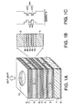
- Fig. 1A is a perspective view showing a configuration of a surface emitting semiconductor laser involving a first embodiment of the present invention
- Fig. 1B is an enlargement of a portion of the active layer and clad layers shown in Fig. 1A
- Fig. 1C is an energy band diagram of the active layer and clad layers shown in Fig. 1B.
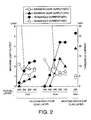
- Fig. 2 is a diagram showing simulation results of the threshold current and the maximum light output when the number of the wells and the well width of the active layer and compositions of the clad layers involving the present embodiment are varied.
- Fig. 3A is a perspective view showing a configuration of a surface emitting semiconductor laser involving a second embodiment of the present invention
- Fig. 3B is a sectional view cut along an A-B profile of Fig. 3A.
- Fig. 4A is a perspective view showing a configuration of a surface emitting semiconductor laser involving a third embodiment of the present invention
- Fig. 4B is a sectional view cut along an A-B profile of Fig. 4A.
- Fig. 5 is a perspective view showing a configuration of a surface emitting semiconductor laser involving a fourth embodiment of the present invention.
- Fig. 6A is a perspective view showing a configuration of a surface emitting semiconductor laser involving a fifth embodiment of the present invention
- Fig. 6B is a sectional view cut along an A-B profile of Fig. 6A.
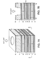
- Fig. 7A is a perspective view showing a configuration of a surface emitting semiconductor laser involving a sixth embodiment of the present invention
- Fig. 7B is a sectional view cut along an A-B profile of Fig. 7A.
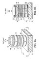
- Fig. 8A is a perspective view showing a configuration of a surface emitting semiconductor laser involving a seventh embodiment of the present invention
- Fig. 8B is a sectional view cut along an A-B profile of Fig. 8A.
- Fig. 9A is a perspective view showing a configuration of a surface emitting semiconductor laser involving an eighth embodiment of the present invention
- Fig. 9B is a sectional view cut along an A-B prolile of Fig. 9A.
- Fig. 10A is a perspective view showing a configuration of an existing surface emitting semiconductor laser
- Fig. 10B is an enlargement of a portion of the active layer and the clad layers shown in Fig. 10A
- Fig. 10C is an energy band diagram of the active layer and clad layers shown in Fig. 10B.
- the present invention while securing a gain, enables to make thinner the thickness of the active layer and to suppress heat generation from the active layer. As a result, an increase of the threshold current at the high temperature operation may be suppressed from occurring, thereby the high temperature properties being improved.
- an In 0.5 (Ga 1-x Al x ) 0.5 P film (herein, x ⁇ 0.8) may be cited.
- current confinement in the active layer may be improved, resulting in enabling to lower the threshold current, thereby an improvement of the high temperature properties being attained.
- the light reflecting layer is the DBR multi-layer film where a Ga 1-x Al x As film (herein, 0.9 ⁇ x ⁇ 0.5) and a Ga 1-y Al y As film (herein, y ⁇ 0.9) are repeatedly stacked in turn.
- a Ga 1-x Al x As film herein, 0.9 ⁇ x ⁇ 0.5
- a Ga 1-y Al y As film herein, y ⁇ 0.9
- the light reflecting film is formed continuously with the active layer and the clad layers in the same furnace. That is, the light reflecting layer may be formed without exposing to an ambient atmosphere. Accordingly, the light reflecting layer may be improved in its quality and fabricating processes thereof may be simplified.
- the light reflecting layer is the DBR multi-layer film where an In 0.5 (Ga 1-x Al x ) 0.5 P film (herein, x ⁇ 0.5) and an In 0.5 (Ga 1-y Al y ) 0.5 P film (herein, y ⁇ 0.9) are repeatedly stacked in turn.
- the light reflecting layer may be formed of the material of the same system with the active layer and the clad layers. Accordingly, the light reflecting layer of low loss may be formed with ease.
- the light exit window of laser light that is exited transmitting through one of the above and below light reflecting layers is arranged in array on the substrate. Thereby, it needs only to pattern the light exit window to integrate a plurality of semiconductor lasers on the same substrate. Accordingly, application to a multi-link and so on may be implemented with ease.
- the DBR multi-layer film includes a circular high resistance region. A current supplied to the active layer due to the circular high resistance region may be blocked and confined, thereby light emission efficiency being improved and the threshold current being lowered.
- the DBR multi-layer film includes therein an AlAs layer, the AlAs layer being circularly surrounded by an oxide region of AlAs. Due to the circular oxide region, the current supplied to the active layer may be blocked and confined, thereby light emission efficiency being improved and the threshold current being lowered.
- an electrode layer transmitting the output laser light is provided on a side, different from the aforementioned clad layer side, of one of the light reflecting layers that are the DBR multi-layer films. Thereby, the current may be smoothly supplied from the electrode layer.
- a substrate is provided, the substrate being hollowed to form the light exit window.
- a side opposite to the substrate may be made a mounting face, thereby, a distance from the mounting face to the active layer becoming shorter, resulting in an improvement of heat dissipation characteristics.
- the DBR multi-layer is circularly surrounded by a buried layer.
- the current supplied to the active layer may be blocked and confined by the circularly buried layer, thereby light emission efficiency being improved and the threshold current being lowered.
- the upper and lower DBR multi-layer films each that are the above and below light reflecting layers include therein an AlAs layer, the AlAs layer being circularly surrounded by an oxide region of AlAs.
- AlAs in place of AlAs, InAs may be used.
- the current supplied to the active layer may be blocked and confined above and below the active layer, thereby, furthermore, light emission efficiency being improved and the threshold current being lowered.
- Fig. 1A is a perspective view showing a configuration of a surface emitting semiconductor laser involving a first embodiment of the present invention.
- a DBR multi-layer film 2 on an n-GaAs substrate 1, a DBR multi-layer film 2, an n-InGaAlP clad layer 3, an MQW active layer 4, a p-InGaAlP clad layer 5, a DBR multi-layer film 6, and a p-GaAs cap layer 7 are stacked in turn.
- the active layer 4 and the clad layers 3 and 5 form a resonator of the surface emitting semiconductor laser, at the active layer 4 in the center thereof a film thickness being designed to be an antinode of a standing wave of one wavelength.
- MOCVD Metal-Organic Chemical Vapor Deposition
- MBE Molecular Beam Epitaxy
- ALE atomic layer Epitaxy
- an n-side electrode 8 is formed, and on the p-GaAs cap layer 7, the p-side electrode 9 is formed. Furthermore, there is formed a disc-like opening in the p-GaAs cap layer 7 and the p-side electrode 9 to form the light exit window 10 for taking out exit light.
- the active layer 4 is formed of for instance an In 0.5 Ga 0.5 P/In 0.5 (Ga 0.5 Al 0.5 ) 0.5 P film; the clad layer 3 being formed of for instance an n-In 0.5 (Ga 0.2 Al 0.8 ) 0.5 P film; the clad layer 5 being formed of for instance a p-In 0.5 (Ga 0.2 Al 0.8 ) 0.5 P film.
- the DBR multi-layer films 2 and 6, in which a film of high refractive index and a film of low refractive index are repeatedly stacked in turn, are preferable to be formed by repeatedly stacking a Ga 1-x Al x As film (herein, 0.9 ⁇ x ⁇ 0.5) and a Ga 1-y Al y As film (herein, y ⁇ 0.9) in turn.
- the DBR multi-layer film 2 may be formed of 54.5 pairs of n-Ga 0.5 Al 0.5 As/Ga 0.05 Al 0.95 As films, the DBR multi-layer film 6 being formed of 34 pairs of p-Ga 0.5 Al 0.5 As/Ga 0.05 Al 0.95 As films.
- Fig. 1B is an enlargement of a portion of the active layer and the clad layers in Fig. 1A.
- an In 0.5 (Ga 0.5 Al 0.5 ) 0.5 P film 4a and an In 0.5 Ga 0.5 P film 4b are repeated stacked in turn; as shown in Fig. 1C, in a portion of the In 0.5 Ga 0.5 P film 4b, a quantum well QW is formed.
- the well width Hb is set in the range of from 4 nm to 6 nm, and the number of the wells Wn being set at one or two.
- a well spacing Ha is preferably set in the range of from approximately 3 to 10 nm.
- the clad layers 3 and 5 are preferably formed of an In 0.5 (Ga 1-x Al x ) 0.5 P film (herein, x ⁇ 0.8), being formed of an n-In 0.5 (Ga 0.2 Al 0.8 ) 0.5 P film for instance.
- Fig. 2 is a diagram showing simulation results of the threshold current and the maximum light output when the number of the wells and the well width of the active layer and the composition of the clad layers involving the present embodiment are varied.
- the composition of the clad layers 3 and 5 being In 0.5 (Ga 0.3 Al 0.7 ) 0.5 P and the well width Hb of the active layer 4 being 7 nm
- the maximum light output decreases, in particular, when a temperature is elevated (from 50°C to 70°C), the maximum light output decreases.
- the threshold current while approximately constant when the number of the wells Wn is increased from one to three, increases when the number of the wells Wn is increased from three to five, in particular, when the temperature is raised (from 50°C to 70°C), this tendency becomes remarkable.
- the maximum light output decreases.
- the threshold current in the case of the number of the wells Wn being from one to three, is approximately constant, when the number of the wells Wn is increased from three to seven, the threshold current increases, in particular, when the temperature is raised (from 50°C to 70°C), this tendency becomes conspicuous.
- the well width of the active layer 4 is from 4 nm to 6 nm and the number of the wells is from one to three, especially when one or two, even under high temperature operation, while suppressing the increase of the threshold current, the maximum light output may be suppressed from lowering.
- the current confinement in the active layer 4 may be improved. Thereby, the threshold current may be lowered and the maximum light output may be increased.
- a case where the p-side electrode 9 is formed in the surroundings of the light exit window 10 is taken by way of illustration.
- a transparent electrode may be formed on the light exit window 10. Thereby, into the active layer 4 below the light exit window 10, the current may be efficiently injected to lower the threshold current.
- the current in the active layer 4 may be effectively confined.
- the clad layers 3 and 5 into a superlattice structure to form multi-quantum barrier (MQB) and thereby causing electrons tending to drain out of the active layer 4 to reflect resonantly, the band gaps of the clad layers 3 and 5 may be effectively increased. That is, the multi-quantum barrier (MQB) may be adopted.
- MQB multi-quantum barrier
- a distorted quantum well structure may be introduced. Thereby, the threshold current may be lowered.
- the active layer 4, other than the InGaP/InGaAlP system multi-layer film, may be an InGaAlP/InGaAlP system multi-layer film.
- the DBR multi-layer films 2 and 6, other than GaAlAs/GaAlAs system multi-layer film may be one formed by repeatedly stacking an In 0.5 (Ga 1-x Al x ) 0.5 film (herein, x ⁇ 0.5) and an In 0.5 (Ga 1-y Al y ) 0.5 P film (herein, y ⁇ 0.9) in turn, thereby also, the reflecting film of low loss being formed with ease.
- Fig. 3A is a perspective view showing a configuration of a surface emitting semiconductor laser involving the second embodiment of the present invention
- Fig. 3B is a sectional view cut along an A-B profile of Fig. 3A.
- the p-side ring electrode 11 is formed, by removing the p-GaAs cap layer 7 inside of the p-side ring electrode 11, the light exit window 10 being formed.
- a high resistance region 12 is formed outside of the p-side ring electrode 11, extending to the p-GaAs cap layer 7 and the DBR multi-layer film 6, a high resistance region 12 is formed outside of the p-side ring electrode 11, extending to the p-GaAs cap layer 7 and the DBR multi-layer film 6, a high resistance region 12 is formed outside of the p-side ring electrode 11, extending to the p-GaAs cap layer 7 and the DBR multi-layer film 6, a high resistance region 12 is formed outside of the p-side electrode 11, for instance.
- the disposition of the high resistance region 12 enables to block and confine the current 16 supplied from the p-side ring electrode 11 at the portion of the high resistance region 12, thereby light emission efficiency being improved and the threshold current being lowered.
- the high resistance region 12 is formed in the p-GaAs cap layer 7 and the DBR multi-layer film 6 is explained.
- the high resistance region 12 may be additionally formed inside the clad layer 5, thereby the current being further blocked.
- Fig. 4A is a perspective view showing a configuration of a surface emitting semiconductor laser involving the third embodiment of the present invention
- Fig. 4B is a sectional view cut along an A-B profile of Fig. 4A.
- the DBR multi-layer film 6 and the p-GaAs cap layer 7 are etched to be cylindrical.
- a p-side ring electrode 13 is formed, and the p-GaAs cap layer 7 inside of the p-side ring electrode 13 is removed. Thereby, the light exit window 10 is formed.
- one or a plurality of AlAs layers 14 is formed on any layers of the DBR multi-layer film 6.
- the AlAs layer 14 is exposed to an oxidizing atmosphere to oxidize a periphery portion of the AlAs layer 14. Thereby, a selectively oxidized ring-like region 15 may be formed inside the DBR multi-layer film 6.
- the current 16 supplied from the p-side ring electrode 13 may be blocked and confined by the selectively oxidized region 15, thereby light emission efficiency being improved and the threshold current being lowered.
- Fig. 5 is a perspective view showing a configuration of a surface emitting semiconductor laser involving the fourth embodiment of the present invention.
- a plurality of light exit windows 10 is formed in array, from the light exit windows 10 each, light being separately and independently taken out.
- the array-like surface emitting semiconductor laser by changing only the mask pattern, may be formed with ease. Accordingly, positioning between pellets each other and mounting processes may be eliminated when arranging the semiconductor laser in array, resulting in simplification of the fabricating process.
- optical components such as optical fiber and lenses may be three-dimensionally mounted with ease, being easily applied to the multi-link or the like.
- Fig. 6A is a perspective view showing a configuration of a surface emitting semiconductor laser involving the fifth embodiment of the present invention
- Fig. 6B is a sectional view cut along an A-B profile in Fig. 6A.
- a transparent electrode 61 is formed on the DBR multi-layer film 6.
- the transparent electrode 61 an ITO (Indium Tin Oxide) film for instance, is one high in transmittance in an wavelength from 600 nm to 700 nm for instance.
- ITO Indium Tin Oxide
- the circular high resistance region 12 is formed.
- the high resistance region 12 may be formed by selectively implanting ions such as protons or the like into the region for instance. From a region surrounded by the high resistance region 12, in an upward direction in the drawing, laser light is exited.
- the disposition of the high resistance region 12 enables to block and confine the current 16 supplied from the transparent electrode 61 at the portion of the high resistance region 12.
- the transparent electrode 61 is formed over an entire surface of the DBR multi-layer film 6, the current may be efficiently injected into the active layer 4. Thereby, the light emission efficiency may be improved and the threshold current may be lowered.
- the high resistance region 12 may be additionally disposed inside of the clad layer 5, thereby the current being further blocked and confined.
- Fig. 7A is a perspective view showing a configuration of a surface emitting semiconductor laser involving the sixth embodiment of the present invention; Fig. 7B being a sectional view cut along an A-B profile of Fig. 7A.
- the p-type electrode 9 is formed, on the back side of the substrate 1 an n-side electrode 8 being formed.
- the high resistance region 12 such as explained in the third and sixth embodiments is formed to block and confine the current injected from the p-type electrode 9.
- a disc-like opening is formed to form the light exit window for taking out emitted light.
- the current to the active layer 4 supplied from the p-type electrode 9 may be blocked due to the high resistance region 12. Thereby, the light emission efficiency may be improved, and the threshold current is lowered.
- the p-type electrode 9 side is used for mounting, a distance between the active layer 4 and the mounting face becomes shorter to be excellent in heat dissipation characteristics. Accordingly, the temperature characteristics may be improved.
- the high resistance region 12 is formed inside of the DBR multi-layer film 2.
- the high resistance region 12 may be additionally formed inside of the clad layer 5, thereby the current being further blocked and confined.
- Fig. 8A is a perspective view showing a configuration of a surface emitting semiconductor laser involving the seventh embodiment of the present invention
- Fig. 8B is a sectional view cut along an A-B profile of Fig. 8A.
- the p-side ring electrode 11 is formed, and by removing the p-GaAs cap layer 7 inside of the p-side ring electrode 11 the light exit window 10 is formed.
- n-type buried layer 81 is formed outside of the p-side ring electrode 11, extending to part of the clad layer 5 an n-type buried layer 81 is formed outside of the p-side ring electrode 11, extending to part of the clad layer 5 an n-type buried layer 81 is formed.
- the n-type buried layer 81 may be formed in the following way, for instance. That is, the outside of the p-side ring electrode 11 is selectively etched extending to the part of the clad layer 5 to form a recess, in the recess an n-semiconductor layer whose refractive index is lower than that of the clad layer 5 being regrown.
- the current 16 supplied from the p-side ring electrode 11 may be blocked and confined at the n-type buried layer 81, thereby light emission efficiency being improved, the threshold current being lowered.
- Fig. 9A is a perspective view showing a configuration of a surface emitting semiconductor laser involving the eighth embodiment of the present invention
- Fig. 9B is a sectional view cut along an A-B profile of Fig. 9A.
- the p-GaAs cap layer 7, the DBR multi-layer film 6, the clad layer 5, the active layer 4, the clad layer 3, and almost all of the DBR multi-layer film 2 are cylindrically etched to form.
- the p-side ring electrode 13 is formed and, by removing the p-GaAs cap layer 7 inside of the p-side ring electrode 13 the light exit window 10 is formed.
- the p-side ring electrode 13 may be formed in rectangle and prismatic etching may be implemented.
- AlAs layers 14 and 92 are formed, respectively.
- the AlAs layers 14 and 92 are exposed to an oxidizing atmosphere to oxidize the periphery thereof 14 and 92, thereby forming selectively oxidized ring regions 15 and 91 inside of the DBR multi-layer films 6 and 2.
- the current 16 supplied from the p-side ring electrode 13 may be blocked and confined by the selectively oxidized region 15, and the current flowing from the active layer 4 to the n-type electrode 8 may be blocked and confined by the selectively oxidized region 91. Thereby, the light emission efficiency may be further improved, and the threshold current may be further lowered.
- the AlAs layers 14 and 92 may be an InAs layer.
- the DBR multi-layer 6 is formed of compound semiconductors for illustration purpose.
- the DBR multi-layer film of the similar function may be formed.
- dielectrics of high refractive index and low refractive index are alternately stacked.
- SiO 2 , SiN x , amorphous Si, alumina and so on may be used.
- the surface emitting semiconductor lasers with the n-GaAs substrate 1 are explained.
- the conduction type may be an opposite one.
Applications Claiming Priority (2)
| Application Number | Priority Date | Filing Date | Title |
|---|---|---|---|
| JP2000353113A JP4024471B2 (ja) | 2000-11-20 | 2000-11-20 | 面発光型半導体レーザ |
| JP2000353113 | 2000-11-20 |
Publications (3)
| Publication Number | Publication Date |
|---|---|
| EP1207598A2 true EP1207598A2 (fr) | 2002-05-22 |
| EP1207598A3 EP1207598A3 (fr) | 2002-10-23 |
| EP1207598B1 EP1207598B1 (fr) | 2004-01-28 |
Family
ID=18825921
Family Applications (1)
| Application Number | Title | Priority Date | Filing Date |
|---|---|---|---|
| EP01126412A Expired - Lifetime EP1207598B1 (fr) | 2000-11-20 | 2001-11-07 | Laser à semi-conducteur à émission de surface |
Country Status (4)
| Country | Link |
|---|---|
| US (1) | US6687276B2 (fr) |
| EP (1) | EP1207598B1 (fr) |
| JP (1) | JP4024471B2 (fr) |
| DE (1) | DE60101887T2 (fr) |
Cited By (3)
| Publication number | Priority date | Publication date | Assignee | Title |
|---|---|---|---|---|
| CN109038217A (zh) * | 2018-10-31 | 2018-12-18 | 厦门乾照半导体科技有限公司 | 延长使用寿命的vcsel芯片及制作方法和电子器件 |
| CN112490851A (zh) * | 2020-11-30 | 2021-03-12 | 长春理工大学 | 上下电极旋错布置的垂直腔面发射半导体激光器 |
| CN109038217B (zh) * | 2018-10-31 | 2024-04-26 | 厦门乾照半导体科技有限公司 | 延长使用寿命的vcsel芯片及制作方法和电子器件 |
Families Citing this family (7)
| Publication number | Priority date | Publication date | Assignee | Title |
|---|---|---|---|---|
| TW586246B (en) * | 2002-10-28 | 2004-05-01 | Super Nova Optoelectronics Cor | Manufacturing method of white light LED and the light-emitting device thereof |
| JP4896440B2 (ja) * | 2005-06-21 | 2012-03-14 | 株式会社リコー | 二次元面発光レーザーアレイおよび光走査装置および画像形成装置 |
| JP5224155B2 (ja) * | 2006-02-03 | 2013-07-03 | 株式会社リコー | 面発光レーザ素子、それを備えた面発光レーザアレイ、面発光レーザアレイを備えた画像形成装置、面発光レーザ素子または面発光レーザアレイを備えた光ピックアップ装置、面発光レーザ素子または面発光レーザアレイを備えた光送信モジュール、面発光レーザ素子または面発光レーザアレイを備えた光送受信モジュールおよび面発光レーザ素子または面発光レーザアレイを備えた光通信システム。 |
| US7693204B2 (en) | 2006-02-03 | 2010-04-06 | Ricoh Company, Ltd. | Surface-emitting laser device and surface-emitting laser array including same |
| CN101322291B (zh) * | 2006-02-03 | 2012-05-09 | 株式会社理光 | 表面发射激光器装置及包含其的表面发射激光器阵列 |
| US7809040B2 (en) | 2007-02-14 | 2010-10-05 | Canon Kabushiki Kaisha | Red surface emitting laser element, image forming device, and image display apparatus |
| US10396241B1 (en) | 2016-08-04 | 2019-08-27 | Apple Inc. | Diffusion revealed blocking junction |
Citations (2)
| Publication number | Priority date | Publication date | Assignee | Title |
|---|---|---|---|---|
| US6008067A (en) * | 1996-12-27 | 1999-12-28 | Motorola, Inc. | Fabrication of visible wavelength vertical cavity surface emitting laser |
| EP1045457A2 (fr) * | 1999-04-15 | 2000-10-18 | Daido Tokushuko Kabushiki Kaisha | Diode émettrice de lumière à puits quantique |
Family Cites Families (11)
| Publication number | Priority date | Publication date | Assignee | Title |
|---|---|---|---|---|
| JPH0590702A (ja) | 1991-09-30 | 1993-04-09 | Toshiba Corp | 半導体レ−ザ装置 |
| EP0544357B1 (fr) * | 1991-11-26 | 1996-09-04 | Koninklijke Philips Electronics N.V. | Diode semiconductrice émettrice de rayonnement |
| JPH0697586A (ja) | 1992-09-17 | 1994-04-08 | Toshiba Corp | 多重量子井戸半導体レーザ装置 |
| JPH06237041A (ja) * | 1993-02-10 | 1994-08-23 | Olympus Optical Co Ltd | 高出力半導体レーザ |
| US5585957A (en) * | 1993-03-25 | 1996-12-17 | Nippon Telegraph And Telephone Corporation | Method for producing various semiconductor optical devices of differing optical characteristics |
| US5351256A (en) * | 1993-04-28 | 1994-09-27 | The United States Of America As Represented By The United States Department Of Energy | Electrically injected visible vertical cavity surface emitting laser diodes |
| US6015980A (en) | 1996-03-08 | 2000-01-18 | The Regents Of The University Of California | Metal layered semiconductor laser |
| US5825796A (en) * | 1996-09-25 | 1998-10-20 | Picolight Incorporated | Extended wavelength strained layer lasers having strain compensated layers |
| US5877038A (en) | 1996-11-27 | 1999-03-02 | The Regents Of The University Of California | Method of making a vertical cavity laser |
| US5923696A (en) * | 1996-12-27 | 1999-07-13 | Motorola, Inc. | Visible light emitting vertical cavity surface emitting laser with gallium phosphide contact layer and method of fabrication |
| JPH10335742A (ja) * | 1997-06-04 | 1998-12-18 | Toshiba Corp | 半導体レーザ装置 |
-
2000
- 2000-11-20 JP JP2000353113A patent/JP4024471B2/ja not_active Expired - Fee Related
-
2001
- 2001-11-05 US US09/992,990 patent/US6687276B2/en not_active Expired - Lifetime
- 2001-11-07 DE DE2001601887 patent/DE60101887T2/de not_active Expired - Lifetime
- 2001-11-07 EP EP01126412A patent/EP1207598B1/fr not_active Expired - Lifetime
Patent Citations (2)
| Publication number | Priority date | Publication date | Assignee | Title |
|---|---|---|---|---|
| US6008067A (en) * | 1996-12-27 | 1999-12-28 | Motorola, Inc. | Fabrication of visible wavelength vertical cavity surface emitting laser |
| EP1045457A2 (fr) * | 1999-04-15 | 2000-10-18 | Daido Tokushuko Kabushiki Kaisha | Diode émettrice de lumière à puits quantique |
Non-Patent Citations (4)
| Title |
|---|
| GAUGGEL H-P ET AL: "Fabrication and operation of first-order GaInP/AlGaInP DFB lasers at room temperature" ELECTRONICS LETTERS, IEE STEVENAGE, GB, vol. 31, no. 5, 2 March 1995 (1995-03-02), pages 367-368, XP006002517 ISSN: 0013-5194 * |
| JALONEN M ET AL: "Oxide-confined resonant cavity red light-emitting diode grown by solid source molecular beam epitaxy" ELECTRONICS LETTERS, IEE STEVENAGE, GB, vol. 33, no. 23, 6 November 1997 (1997-11-06), pages 1989-1990, XP006008149 ISSN: 0013-5194 * |
| SCHNEIDER R P ET AL: "MOVPE GROWTH OF INALGAP-BASED VISIBLE VERTICAL-CAVITY SURFACE- EMITTING LASERS" JOURNAL OF CRYSTAL GROWTH, NORTH-HOLLAND PUBLISHING CO. AMSTERDAM, NL, vol. 124, no. 1/4, 1 November 1992 (1992-11-01), pages 763-771, XP000411855 ISSN: 0022-0248 * |
| SMOWTON P M ET AL: "INVITED PAPER ROLE OF SUBLINEAR GAIN-CURRENT RELATIONSHIP IN COMPRESSIVE AND TENSILE STRAINED 630 NM GAINP LASERS" INTERNATIONAL JOURNAL OF OPTOELECTRONICS (INCL.OPTICAL COMPUTING & PROCESSING), TAYLOR & FRANCIS, LONDON, GB, vol. 10, no. 5, 1 September 1995 (1995-09-01), pages 383-391, XP000635946 ISSN: 0952-5432 * |
Cited By (4)
| Publication number | Priority date | Publication date | Assignee | Title |
|---|---|---|---|---|
| CN109038217A (zh) * | 2018-10-31 | 2018-12-18 | 厦门乾照半导体科技有限公司 | 延长使用寿命的vcsel芯片及制作方法和电子器件 |
| CN109038217B (zh) * | 2018-10-31 | 2024-04-26 | 厦门乾照半导体科技有限公司 | 延长使用寿命的vcsel芯片及制作方法和电子器件 |
| CN112490851A (zh) * | 2020-11-30 | 2021-03-12 | 长春理工大学 | 上下电极旋错布置的垂直腔面发射半导体激光器 |
| CN112490851B (zh) * | 2020-11-30 | 2022-07-12 | 长春理工大学 | 上下电极旋错布置的垂直腔面发射半导体激光器 |
Also Published As
| Publication number | Publication date |
|---|---|
| JP2002158406A (ja) | 2002-05-31 |
| DE60101887D1 (de) | 2004-03-04 |
| US6687276B2 (en) | 2004-02-03 |
| US20020061043A1 (en) | 2002-05-23 |
| DE60101887T2 (de) | 2004-11-18 |
| JP4024471B2 (ja) | 2007-12-19 |
| EP1207598B1 (fr) | 2004-01-28 |
| EP1207598A3 (fr) | 2002-10-23 |
Similar Documents
| Publication | Publication Date | Title |
|---|---|---|
| US6803597B2 (en) | Semiconductor light-emitting device using graded multi quantum barrier | |
| JP4265875B2 (ja) | 面発光半導体レーザの製造方法 | |
| JP4728656B2 (ja) | 面発光レーザ素子 | |
| KR100374796B1 (ko) | P형 전극과 활성층 사이에 효과적인 정공 확산을 위한 스페이서를 구비하는 GaN 면 발광 레이저 다이오드 및그 제조 방법 | |
| CN211929898U (zh) | 垂直腔面发射激光器件 | |
| JPH10233557A (ja) | 半導体発光素子 | |
| JPH05275798A (ja) | レーザダイオード | |
| US7816163B2 (en) | Radiation-emitting semiconductor body for a vertically emitting laser and method for producing same | |
| US20070153856A1 (en) | Semiconductor laser device | |
| EP1207598B1 (fr) | Laser à semi-conducteur à émission de surface | |
| US7459719B2 (en) | Superlattice optical semiconductor device where each barrier layer has high content of group III elements in center portion and low content near well layer | |
| US6728283B2 (en) | Semiconductor laser and photo module using the same | |
| JP2003347670A (ja) | 面発光半導体レーザ素子及びレーザアレイ | |
| JP4045639B2 (ja) | 半導体レーザおよび半導体発光素子 | |
| JP2004253802A (ja) | 改善された温度特性を有するGaAsSb/GaAs素子 | |
| JP2007087994A (ja) | 面発光半導体レーザ素子 | |
| JP2006332623A (ja) | 半導体レーザ装置 | |
| EP1109231A2 (fr) | Dispositif semi-conducteur émetteur de lumière et méthode de fabrication | |
| US20080198887A1 (en) | Semiconductor laser device and method of fabricating the same | |
| Zou et al. | Very-low-threshold, strained In/sub y/Ga/sub 1-y/As-GaAs quantum-well lasers defined by impurity-induced disordering | |
| JP2006019470A (ja) | 面発光半導体レーザおよび光モジュール | |
| JP2002033553A (ja) | 半導体レーザ装置及びその製造方法 | |
| JPH077219A (ja) | 半導体レーザ素子 | |
| KR100372479B1 (ko) | 반도체 레이저장치 및 그 제조방법 | |
| JPH05226765A (ja) | 半導体レーザアレイ装置 |
Legal Events
| Date | Code | Title | Description |
|---|---|---|---|
| PUAI | Public reference made under article 153(3) epc to a published international application that has entered the european phase |
Free format text: ORIGINAL CODE: 0009012 |
|
| 17P | Request for examination filed |
Effective date: 20011107 |
|
| AX | Request for extension of the european patent |
Free format text: AL;LT;LV;MK;RO;SI |
|
| PUAL | Search report despatched |
Free format text: ORIGINAL CODE: 0009013 |
|
| AK | Designated contracting states |
Kind code of ref document: A3 Designated state(s): AT BE CH CY DE DK ES FI FR GB GR IE IT LI LU MC NL PT SE TR |
|
| AX | Request for extension of the european patent |
Free format text: AL;LT;LV;MK;RO;SI |
|
| AKX | Designation fees paid |
Designated state(s): DE FR GB |
|
| GRAP | Despatch of communication of intention to grant a patent |
Free format text: ORIGINAL CODE: EPIDOSNIGR1 |
|
| GRAS | Grant fee paid |
Free format text: ORIGINAL CODE: EPIDOSNIGR3 |
|
| GRAA | (expected) grant |
Free format text: ORIGINAL CODE: 0009210 |
|
| AK | Designated contracting states |
Kind code of ref document: B1 Designated state(s): DE FR GB |
|
| REG | Reference to a national code |
Ref country code: GB Ref legal event code: FG4D |
|
| REG | Reference to a national code |
Ref country code: IE Ref legal event code: FG4D |
|
| REF | Corresponds to: |
Ref document number: 60101887 Country of ref document: DE Date of ref document: 20040304 Kind code of ref document: P |
|
| ET | Fr: translation filed | ||
| PLBE | No opposition filed within time limit |
Free format text: ORIGINAL CODE: 0009261 |
|
| STAA | Information on the status of an ep patent application or granted ep patent |
Free format text: STATUS: NO OPPOSITION FILED WITHIN TIME LIMIT |
|
| 26N | No opposition filed |
Effective date: 20041029 |
|
| REG | Reference to a national code |
Ref country code: FR Ref legal event code: ST Effective date: 20080930 |
|
| PG25 | Lapsed in a contracting state [announced via postgrant information from national office to epo] |
Ref country code: FR Free format text: LAPSE BECAUSE OF NON-PAYMENT OF DUE FEES Effective date: 20071130 |
|
| PGFP | Annual fee paid to national office [announced via postgrant information from national office to epo] |
Ref country code: GB Payment date: 20101103 Year of fee payment: 10 |
|
| REG | Reference to a national code |
Ref country code: FR Ref legal event code: D3 Effective date: 20121106 |
|
| PGFP | Annual fee paid to national office [announced via postgrant information from national office to epo] |
Ref country code: FR Payment date: 20120918 Year of fee payment: 11 |
|
| PGRI | Patent reinstated in contracting state [announced from national office to epo] |
Ref country code: FR Effective date: 20121106 |
|
| GBPC | Gb: european patent ceased through non-payment of renewal fee |
Effective date: 20121107 |
|
| REG | Reference to a national code |
Ref country code: FR Ref legal event code: ST Effective date: 20130731 |
|
| PG25 | Lapsed in a contracting state [announced via postgrant information from national office to epo] |
Ref country code: GB Free format text: LAPSE BECAUSE OF NON-PAYMENT OF DUE FEES Effective date: 20121107 Ref country code: FR Free format text: LAPSE BECAUSE OF NON-PAYMENT OF DUE FEES Effective date: 20121130 |
|
| PGFP | Annual fee paid to national office [announced via postgrant information from national office to epo] |
Ref country code: DE Payment date: 20161101 Year of fee payment: 16 |
|
| REG | Reference to a national code |
Ref country code: DE Ref legal event code: R119 Ref document number: 60101887 Country of ref document: DE |
|
| PG25 | Lapsed in a contracting state [announced via postgrant information from national office to epo] |
Ref country code: DE Free format text: LAPSE BECAUSE OF NON-PAYMENT OF DUE FEES Effective date: 20180602 |