EP1207068B1 - Toit de véhicule avec au moins deux panneaus installés l'un derrière l'autre - Google Patents
Toit de véhicule avec au moins deux panneaus installés l'un derrière l'autre Download PDFInfo
- Publication number
- EP1207068B1 EP1207068B1 EP20010126170 EP01126170A EP1207068B1 EP 1207068 B1 EP1207068 B1 EP 1207068B1 EP 20010126170 EP20010126170 EP 20010126170 EP 01126170 A EP01126170 A EP 01126170A EP 1207068 B1 EP1207068 B1 EP 1207068B1
- Authority
- EP
- European Patent Office
- Prior art keywords
- panel
- vehicle roof
- openable vehicle
- roof
- cover
- Prior art date
- Legal status (The legal status is an assumption and is not a legal conclusion. Google has not performed a legal analysis and makes no representation as to the accuracy of the status listed.)
- Expired - Lifetime
Links
Images


Classifications
-
- B—PERFORMING OPERATIONS; TRANSPORTING
- B60—VEHICLES IN GENERAL
- B60J—WINDOWS, WINDSCREENS, NON-FIXED ROOFS, DOORS, OR SIMILAR DEVICES FOR VEHICLES; REMOVABLE EXTERNAL PROTECTIVE COVERINGS SPECIALLY ADAPTED FOR VEHICLES
- B60J7/00—Non-fixed roofs; Roofs with movable panels, e.g. rotary sunroofs
- B60J7/02—Non-fixed roofs; Roofs with movable panels, e.g. rotary sunroofs of sliding type, e.g. comprising guide shoes
- B60J7/04—Non-fixed roofs; Roofs with movable panels, e.g. rotary sunroofs of sliding type, e.g. comprising guide shoes with rigid plate-like element or elements, e.g. open roofs with harmonica-type folding rigid panels
- B60J7/047—Non-fixed roofs; Roofs with movable panels, e.g. rotary sunroofs of sliding type, e.g. comprising guide shoes with rigid plate-like element or elements, e.g. open roofs with harmonica-type folding rigid panels movable to overlapping or nested relationship
Definitions
- the invention relates to a vehicle roof with at least two lids arranged one behind the other, which together seal a roof opening, and of which at least one cover for releasing a part of the roof opening is displaceable under the other cover, according to the preamble of patent claim 1.
- Such a vehicle roof is known from US-A-4 498 701.
- a rear lid under which a solid plate is arranged, can be raised and a front, opposite the rear cover a little narrower and trapezoidal lid is movable in the space between the rear cover and the plate.
- the rear part of the roof opening is rectangular. The roof opening can only be exposed in the area of the front cover for ventilation purposes.
- Another vehicle roof is known from DE 42 27 400 C2.
- the lids there also have a rectangular shape and therefore adapt poorly to dynamically widening rear wedge-shaped body shapes.
- the lowered lid also affects the headroom of the occupants.
- DE 43 06 451 C1 a folding roof has become known, which adapts itself by means of transversely guided at the ends guided bow to a forwardly expanding roof opening.
- a roof with a lid is known which optionally closes a rearwardly tapered roof opening or releases by displacement along non-parallel guides.
- the object of the invention is to provide a vehicle roof, in which two successively arranged, adaptable to the roof contour cover with a simple mechanism can be actuated. This object is solved by the features of patent claim 1.
- the guide rails of the sliding cover extend transversely to the vehicle longitudinal axis preferably within the guiding and / or Ausstellstoff of the other lid.
- the roof opening has the shape of a trapezoid.
- the shape of the roof opening can be perfectly adapted to the shape of the entire roof contour even with a wedge-shaped rearwardly widening vehicle.
- a narrower lid is arranged in front in the direction of travel. This is preferably movable under the underlying wider lid.
- the wider lid can be raised from its closed position by means of a simple lifting mechanism, while the narrower lid can be moved with a simple sliding mechanism under the raised wider lid.
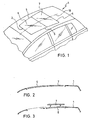
- a first embodiment shown in FIGS. 1 to 6 is characterized in that in a vehicle roof 1, a roof opening 2 by two successively arranged cover 6 or 7 closable or at least partially releasable, wherein the roof opening 2, starting from its front edge 3 to its trailing edge 4 has a widening shape, in which the side edges 5 are straight, so that the overall shape of a trapezoid, or, according to the alternative drawn in Figures 9 and 10, the side edges 5 assume the contour of a curved path 17.
- Both covers 6 and 7 are arranged directly one behind the other and preferably in the closed position flush with each other.
- the front edge 6V of the front cover 6 directly adjoins the front edge 3 of the roof opening 2.
- the trailing edge 6H of the front lid 6 directly adjoins the leading edge 7V of the rear lid 7.
- the trailing edge 7H of the rear lid 7 directly adjoins the trailing edge 4 of the roof opening 2.
- the trapezoidal or even of a lateral curved path 17 limited contour of the roof opening 2 and the corresponding cover 6 and 7 is preferably symmetrical starting from a roof center 18. However, asymmetrical shapes are also feasible.
- the laterally resulting due to the expansion of the roof opening in the rear area resulting extended range of Roof opening 2 is designated by the reference numeral 10 in FIGS. 8 to 10.
- the guide rails 9 are arranged for the rear cover 7.
- the actuating mechanism shown in FIG. 11 is suitable.
- the vehicle roof can first be opened in a first opening step according to FIG. 6B such that the rear cover 7 with its rear edge 7H rises above the fixed vehicle roof 1 is raised.
- the front cover 6 remains closed.
- the rear lid 7 is additionally raised with its front edge 7V, so that it is then located approximately parallel to the fixed vehicle roof 1 above its level and around a ventilation gap relative to the roof opening 2 releases.
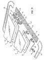
- the front cover 6 is composed of a cover plate 21, preferably made of a transparent material such as glass or plastic, and a cover frame 22 stiffening the cover plate 21 from below, are integrally formed on the side tabs for a connection with sliding shoes 16 are designed.
- the sliding shoes 16 are connected via a drive cable 20 with an electric motor 19, which is arranged in the region of a front frame part 25. By displacement of the drive cable 20, the sliding blocks 16 in the guide rail 8 are longitudinally displaceable.
- the rear cover 7 is composed of a likewise preferably made of transparent material such as glass or plastic cover plate 23 and a stiffening from below the lid frame 24 together.
- On the cover frame 24 are in turn laterally formed tabs on which a cover gate 15 is mounted.
- the cover gate 15 has guide pins which are in engagement with a front slot slot 12 and a rear slot slot 13 of a Ausstellkulisse 11, which in turn is provided with sliding blocks 14 and is slidably guided in the guide rail 9 with these.
- a drive cable 27 is provided, which is in drive connection with an electric motor, not shown, which is arranged on a rear frame part 26.
- the rear frame part 26 and the front frame part 25 are connected to the preferably formed as a single profile guide rails 8 and 9 on both sides and thereby form a closed frame on which the openable vehicle roof with the two covers 6 and 7 pre-assembled as a unit to the vehicle manufacturer can be transported.
- the drive cables 20 and 27 can also be actuated by hand cranks or the like.
- the guide pins (not shown) on the cover scenes 15 are in the closed state of the rear cover 7 at the front ends of the guide slots 12 and 13 at.
- the Ausstellkulisse 11 is moved by means of the drive cable 27 by an amount to the front, wherein the rear guide pin on the Ramp of the rear link slot 13 is raised.
- the front guide pin still remains in the horizontal front portion of the front link slot.
- the rear guide pin passes through the upper horizontal portion of the rear slot slot 13 and thus does not change the height length of the lid 7. So that the cover gate 15 is not co-displaced by friction forces during the displacement of the Ausstellkulisse 11, either the cover gate 15 or the guide pins, not shown additionally guided in fixed guides, which allow only a vertical but no horizontal movement.
- the front cover 6 is displaceable by means of a simple displacement mechanism, which consists only of the sliding blocks 16 arranged on the cover frame 22, of which at least one is connected to the drive cable 20 for longitudinal displacement in the guide rail 8.
- a simple displacement mechanism which consists only of the sliding blocks 16 arranged on the cover frame 22, of which at least one is connected to the drive cable 20 for longitudinal displacement in the guide rail 8.
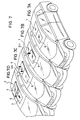
- the front cover 6 is likewise provided with a lifting mechanism, so that starting from the closed position shown in FIG. 7A, the cover 6 with its trailing edge 6H in FIG a fan position can be issued.
- the lid 7 can be raised completely by means of the lifting mechanism described above or can also be raised as an intermediate step with its trailing edge, in which case two separate ventilation gaps are released at both trailing edges 6H and 7H.
- the fan position shown in FIG. 7C a large ventilation gap emerges from the trailing edge 7H of the rear lid to the side area of the front lid 6 exposed.
- the vehicle roof according to the invention has the advantage that it allows different opening variants of a two-decker roof with a very simple mechanism and that it can be adapted due to the expanding roof opening as a design and style element on a vehicle according to its roof contour. The fact that none of the lid must be lowered down, the headroom for the occupants is not affected in any phase.
Landscapes
- Engineering & Computer Science (AREA)
- Mechanical Engineering (AREA)
- Body Structure For Vehicles (AREA)
- Vehicle Step Arrangements And Article Storage (AREA)
Claims (10)
- Toit ouvrant de véhicule- avec au moins deux panneaux (6, 7) disposés l'un à la suite de l'autre,- dont l'un est un panneau plus étroit (6),- et l'autre un panneau plus large (7),- l'un ou l'autre des deux panneaux pouvant être coulissé au-dessus ou en dessous de l'autre panneau afin de dégager une partie d'une ouverture de toit (2),- les panneaux (6, 7) fermant conjointement l'ouverture de toit (2),caractérisé en ce que- l'ouverture de toit (2) présente un bord avant plus étroit (3) et un bord arrière plus large (4), avec une forme allant en s'élargissant du bord avant (3) au bord arrière (4),- sachant qu'on obtient dans la région arrière de la forme allant en s'élargissant une région (10) s'élargissant latéralement,- sachant que des moyens (9, 11, 15) de guidage et/ou de relevage pour le panneau plus large (7) sont disposés sur la région extérieure, considéré transversalement à l'axe longitudinal (18) du véhicule, du panneau plus large (7) ainsi que dans la région élargie (10) de l'ouverture de toit (2).
- Toit ouvrant de véhicule selon la revendication 1, caractérisé en ce que des rails de guidage (8) du panneau coulissant (6) s'étendent, considéré transversalement à l'axe longitudinal du véhicule, à l'intérieur des moyens (9, 11) de guidage et/ou de relevage de l'autre panneau (7).
- Toit ouvrant de véhicule selon l'une des revendications précédentes, caractérisé en ce que l'ouverture de toit (2) présente la forme d'un trapèze.
- Toit ouvrant de véhicule selon la revendication 1 ou 2, caractérisé en ce que les bords latéraux (5) de l'ouverture de toit suivent une trajectoire courbe (17).
- Toit ouvrant de véhicule selon l'une des revendications précédentes, caractérisé en ce que le panneau étroit (6) est disposé à l'avant dans la direction de marche.
- Toit ouvrant de véhicule selon l'une des revendications précédentes, caractérisé en ce que le panneau plus étroit (6) peut être déplacé sous le panneau plus large (7).
- Toit ouvrant de véhicule selon l'une des revendications précédentes, caractérisé en ce que le panneau plus large (7) peut être soulevé à partir de sa position fermée.
- Toit ouvrant de véhicule selon la revendication 7, caractérisé en ce que le panneau plus large (7) peut être relevé par son bord arrière (7H) dans une position de ventilation.
- Toit ouvrant de véhicule selon l'une des revendications précédentes, caractérisé en ce que le panneau plus étroit (6) peut être relevé par son bord arrière (6H) dans une position de ventilation.
- Toit ouvrant de véhicule selon l'une des revendications précédentes, caractérisé en ce que les deux panneaux (6, 7) sont disposés à fleur l'un de l'autre en position fermée.
Applications Claiming Priority (2)
| Application Number | Priority Date | Filing Date | Title |
|---|---|---|---|
| DE10057167 | 2000-11-16 | ||
| DE2000157167 DE10057167C2 (de) | 2000-11-16 | 2000-11-16 | Fahrzeugdach mit wenigstens zwei hintereinander angeordneten Deckeln |
Publications (3)
| Publication Number | Publication Date |
|---|---|
| EP1207068A2 EP1207068A2 (fr) | 2002-05-22 |
| EP1207068A3 EP1207068A3 (fr) | 2002-10-16 |
| EP1207068B1 true EP1207068B1 (fr) | 2007-04-11 |
Family
ID=7663728
Family Applications (1)
| Application Number | Title | Priority Date | Filing Date |
|---|---|---|---|
| EP20010126170 Expired - Lifetime EP1207068B1 (fr) | 2000-11-16 | 2001-11-03 | Toit de véhicule avec au moins deux panneaus installés l'un derrière l'autre |
Country Status (2)
| Country | Link |
|---|---|
| EP (1) | EP1207068B1 (fr) |
| DE (2) | DE10057167C2 (fr) |
Families Citing this family (6)
| Publication number | Priority date | Publication date | Assignee | Title |
|---|---|---|---|---|
| DE10238064A1 (de) | 2002-08-20 | 2004-03-04 | Arvinmeritor Gmbh | Dachmodul mit verschiebbarem Deckel und starrer Dichtleiste |
| DE10330786B4 (de) * | 2003-07-07 | 2006-04-06 | Webasto Ag | Öffnungsfähiges Panoramadach für ein Fahrzeug |
| DE10353009B4 (de) * | 2003-11-13 | 2011-05-26 | Bayerische Motoren Werke Aktiengesellschaft | Schiebehebedach mit wenigstens zwei Deckeln für Fahrzeuge |
| US7229126B2 (en) * | 2003-12-10 | 2007-06-12 | Webasto Ag | Motor vehicle roof with two openable covers |
| EP1834820A1 (fr) * | 2006-03-13 | 2007-09-19 | ArvinMeritor GmbH | Toit panoramique |
| CN113954608A (zh) * | 2021-11-30 | 2022-01-21 | 上汽通用汽车有限公司 | 一种天窗总成及汽车 |
Family Cites Families (10)
| Publication number | Priority date | Publication date | Assignee | Title |
|---|---|---|---|---|
| FR2527256A2 (fr) * | 1982-03-01 | 1983-11-25 | Heuliez Dea | Dispositif d'ouverture a surface decouvrable, notamment toit ouvrant pour vehicule automobile |
| JPH0692206B2 (ja) * | 1986-04-15 | 1994-11-16 | ダイキヨ−・ベバスト株式会社 | 乗物屋根のサンル−フ装置 |
| JPH0517298Y2 (fr) * | 1987-01-28 | 1993-05-10 | ||
| DE68906087T2 (de) * | 1988-06-18 | 1993-07-29 | Britax Ltd | Schiebedach fuer kraftfahrzeuge. |
| US5197779A (en) * | 1989-06-27 | 1993-03-30 | Mazda Motor Corporation | Power sliding sunroof |
| DE4008145A1 (de) * | 1990-03-14 | 1991-09-19 | Bayerische Motoren Werke Ag | Schiebehebedach mit zwei deckeln fuer fahrzeuge |
| DE4227400C2 (de) * | 1992-08-19 | 1997-07-17 | Webasto Karosseriesysteme | Schiebedach |
| DE4306451C1 (de) * | 1993-03-02 | 1994-03-31 | Webasto Karosseriesysteme | Faltdach eines Fahrzeuges |
| NL1009743C2 (nl) * | 1998-07-27 | 2000-01-28 | Inalfa Ind Bv | Open-dakconstructie voor een voertuig, alsmede een met een dergelijke open-dakconstructie uitgevoerd voertuig. |
| DE10002457C2 (de) * | 2000-01-21 | 2001-03-08 | Audi Ag | Schiebedach |
-
2000
- 2000-11-16 DE DE2000157167 patent/DE10057167C2/de not_active Expired - Fee Related
-
2001
- 2001-11-03 EP EP20010126170 patent/EP1207068B1/fr not_active Expired - Lifetime
- 2001-11-03 DE DE50112319T patent/DE50112319D1/de not_active Expired - Fee Related
Also Published As
| Publication number | Publication date |
|---|---|
| EP1207068A3 (fr) | 2002-10-16 |
| EP1207068A2 (fr) | 2002-05-22 |
| DE10057167C2 (de) | 2002-11-14 |
| DE50112319D1 (de) | 2007-05-24 |
| DE10057167A1 (de) | 2002-06-06 |
Similar Documents
| Publication | Publication Date | Title |
|---|---|---|
| DE3202646C2 (de) | Ausstell-Schiebedach für Kraftfahrzeuge | |
| DE19520348C1 (de) | Windabweiser | |
| DE3442599C2 (de) | Schiebehebedach für Fahrzeuge | |
| DE3444593A1 (de) | Absenkvorrichtung fuer die heckscheibe von fahrzeugen | |
| DE3347962C2 (fr) | ||
| DE4112246C2 (fr) | ||
| DE4005789A1 (de) | Sonnendach fuer kraftfahrzeuge | |
| EP2285608B1 (fr) | Toit de véhicule équipé d un toit ouvrant coulissant vers l extérieur | |
| EP0720927B1 (fr) | Toit de véhicule pourvu d'une ouverture pivotante du panneau de toit | |
| WO2013170993A1 (fr) | Toit de véhicule comprenant deux éléments de panneau | |
| DE10329536B4 (de) | Fahrzeugdach | |
| EP1338455B1 (fr) | Déflecteur de vent pour toit ouvrant de véhicule | |
| EP0218020B1 (fr) | Toit ouvrant pour véhicules automobiles | |
| DE3635924A1 (de) | Fahrzeugtuer oder karosserieabschnitt, insbesondere fuer einen personenkraftwagen | |
| EP1207068B1 (fr) | Toit de véhicule avec au moins deux panneaus installés l'un derrière l'autre | |
| DE4111931C1 (en) | Slide canopy for car sun roof - in two parts, one telescopically insertable, at least partly, into second part | |
| DE10158174A1 (de) | Schiebehebedach für Fahrzeuge | |
| DE3438360C2 (fr) | ||
| DE4041908C1 (en) | Sliding roof for motor vehicle - has CAM surfaces on cross-member to guide leading canopy over rear canopy | |
| EP0826538B1 (fr) | Toit de véhicule | |
| DE10062156B4 (de) | Fahrzeugdach mit zwei hintereinander angeordneten, verschiebbaren Dachelementen | |
| DE10106432B4 (de) | Fahrzeug | |
| DE19940519C1 (de) | Fahrzeugdach mit Schiebedeckel und Schiebehimmel | |
| DE10215966A1 (de) | Öffnungsfähiges Fahrzeugdach | |
| EP0836958B1 (fr) | Toit coulissant pour véhicule |
Legal Events
| Date | Code | Title | Description |
|---|---|---|---|
| PUAI | Public reference made under article 153(3) epc to a published international application that has entered the european phase |
Free format text: ORIGINAL CODE: 0009012 |
|
| AX | Request for extension of the european patent |
Free format text: AL;LT;LV;MK;RO;SI |
|
| PUAL | Search report despatched |
Free format text: ORIGINAL CODE: 0009013 |
|
| AK | Designated contracting states |
Kind code of ref document: A3 Designated state(s): AT BE CH CY DE DK ES FI FR GB GR IE IT LI LU MC NL PT SE TR |
|
| AX | Request for extension of the european patent |
Free format text: AL;LT;LV;MK;RO;SI |
|
| RIC1 | Information provided on ipc code assigned before grant |
Free format text: 7B 60J 7/047 A, 7B 60J 7/043 B |
|
| 17P | Request for examination filed |
Effective date: 20030320 |
|
| AKX | Designation fees paid |
Designated state(s): DE FR GB NL |
|
| GRAP | Despatch of communication of intention to grant a patent |
Free format text: ORIGINAL CODE: EPIDOSNIGR1 |
|
| GRAS | Grant fee paid |
Free format text: ORIGINAL CODE: EPIDOSNIGR3 |
|
| GRAA | (expected) grant |
Free format text: ORIGINAL CODE: 0009210 |
|
| AK | Designated contracting states |
Kind code of ref document: B1 Designated state(s): DE FR GB NL |
|
| REG | Reference to a national code |
Ref country code: GB Ref legal event code: FG4D Free format text: NOT ENGLISH |
|
| GBT | Gb: translation of ep patent filed (gb section 77(6)(a)/1977) |
Effective date: 20070418 |
|
| REF | Corresponds to: |
Ref document number: 50112319 Country of ref document: DE Date of ref document: 20070524 Kind code of ref document: P |
|
| ET | Fr: translation filed | ||
| PGFP | Annual fee paid to national office [announced via postgrant information from national office to epo] |
Ref country code: NL Payment date: 20071104 Year of fee payment: 7 Ref country code: DE Payment date: 20071101 Year of fee payment: 7 |
|
| PLBE | No opposition filed within time limit |
Free format text: ORIGINAL CODE: 0009261 |
|
| STAA | Information on the status of an ep patent application or granted ep patent |
Free format text: STATUS: NO OPPOSITION FILED WITHIN TIME LIMIT |
|
| 26N | No opposition filed |
Effective date: 20080114 |
|
| PGFP | Annual fee paid to national office [announced via postgrant information from national office to epo] |
Ref country code: GB Payment date: 20071031 Year of fee payment: 7 Ref country code: FR Payment date: 20071108 Year of fee payment: 7 |
|
| GBPC | Gb: european patent ceased through non-payment of renewal fee |
Effective date: 20081103 |
|
| PG25 | Lapsed in a contracting state [announced via postgrant information from national office to epo] |
Ref country code: NL Free format text: LAPSE BECAUSE OF NON-PAYMENT OF DUE FEES Effective date: 20090601 |
|
| NLV4 | Nl: lapsed or anulled due to non-payment of the annual fee |
Effective date: 20090601 |
|
| REG | Reference to a national code |
Ref country code: FR Ref legal event code: ST Effective date: 20090731 |
|
| PG25 | Lapsed in a contracting state [announced via postgrant information from national office to epo] |
Ref country code: DE Free format text: LAPSE BECAUSE OF NON-PAYMENT OF DUE FEES Effective date: 20090603 |
|
| PG25 | Lapsed in a contracting state [announced via postgrant information from national office to epo] |
Ref country code: GB Free format text: LAPSE BECAUSE OF NON-PAYMENT OF DUE FEES Effective date: 20081103 |
|
| PG25 | Lapsed in a contracting state [announced via postgrant information from national office to epo] |
Ref country code: FR Free format text: LAPSE BECAUSE OF NON-PAYMENT OF DUE FEES Effective date: 20081130 |