EP1207013A1 - Procédé pour augmenter la durée de vie des attaches d'aubes sur un rotor - Google Patents
Procédé pour augmenter la durée de vie des attaches d'aubes sur un rotor Download PDFInfo
- Publication number
- EP1207013A1 EP1207013A1 EP01402916A EP01402916A EP1207013A1 EP 1207013 A1 EP1207013 A1 EP 1207013A1 EP 01402916 A EP01402916 A EP 01402916A EP 01402916 A EP01402916 A EP 01402916A EP 1207013 A1 EP1207013 A1 EP 1207013A1
- Authority
- EP
- European Patent Office
- Prior art keywords
- sonotrode
- balls
- rim
- groove
- mouth
- Prior art date
- Legal status (The legal status is an assumption and is not a legal conclusion. Google has not performed a legal analysis and makes no representation as to the accuracy of the status listed.)
- Granted
Links
- 238000000034 method Methods 0.000 title claims description 26
- 238000005422 blasting Methods 0.000 claims abstract description 41
- 230000006835 compression Effects 0.000 claims abstract description 12
- 238000007906 compression Methods 0.000 claims abstract description 12
- 239000003595 mist Substances 0.000 claims abstract description 5
- 238000009527 percussion Methods 0.000 claims abstract description 5
- 238000005480 shot peening Methods 0.000 claims description 25
- 210000005069 ears Anatomy 0.000 claims description 18
- 230000000295 complement effect Effects 0.000 claims description 7
- 230000036316 preload Effects 0.000 claims description 7
- PXHVJJICTQNCMI-UHFFFAOYSA-N Nickel Chemical compound [Ni] PXHVJJICTQNCMI-UHFFFAOYSA-N 0.000 claims description 6
- 239000011324 bead Substances 0.000 claims description 6
- 239000000463 material Substances 0.000 claims description 6
- 238000007789 sealing Methods 0.000 claims description 6
- 229910000601 superalloy Inorganic materials 0.000 claims description 5
- 229910000831 Steel Inorganic materials 0.000 claims description 4
- 239000010959 steel Substances 0.000 claims description 4
- VYZAMTAEIAYCRO-UHFFFAOYSA-N Chromium Chemical compound [Cr] VYZAMTAEIAYCRO-UHFFFAOYSA-N 0.000 claims description 3
- 229910001069 Ti alloy Inorganic materials 0.000 claims description 3
- 229910052804 chromium Inorganic materials 0.000 claims description 3
- 239000011651 chromium Substances 0.000 claims description 3
- 238000001816 cooling Methods 0.000 claims description 3
- 229910052759 nickel Inorganic materials 0.000 claims description 3
- 102220548131 Cell division cycle-associated 7-like protein_F17A_mutation Human genes 0.000 description 9
- 230000000694 effects Effects 0.000 description 4
- 238000009304 pastoral farming Methods 0.000 description 4
- 238000011084 recovery Methods 0.000 description 4
- 239000011248 coating agent Substances 0.000 description 3
- 238000000576 coating method Methods 0.000 description 3
- 238000002604 ultrasonography Methods 0.000 description 3
- 230000003247 decreasing effect Effects 0.000 description 2
- 230000003116 impacting effect Effects 0.000 description 2
- 230000002093 peripheral effect Effects 0.000 description 2
- 230000035939 shock Effects 0.000 description 2
- 102220520885 DCN1-like protein 1_F15A_mutation Human genes 0.000 description 1
- 229910018487 Ni—Cr Inorganic materials 0.000 description 1
- RTAQQCXQSZGOHL-UHFFFAOYSA-N Titanium Chemical compound [Ti] RTAQQCXQSZGOHL-UHFFFAOYSA-N 0.000 description 1
- 229910045601 alloy Inorganic materials 0.000 description 1
- 239000000956 alloy Substances 0.000 description 1
- XAGFODPZIPBFFR-UHFFFAOYSA-N aluminium Chemical compound [Al] XAGFODPZIPBFFR-UHFFFAOYSA-N 0.000 description 1
- 229910052782 aluminium Inorganic materials 0.000 description 1
- 238000013459 approach Methods 0.000 description 1
- 239000000919 ceramic Substances 0.000 description 1
- VNNRSPGTAMTISX-UHFFFAOYSA-N chromium nickel Chemical compound [Cr].[Ni] VNNRSPGTAMTISX-UHFFFAOYSA-N 0.000 description 1
- 230000000052 comparative effect Effects 0.000 description 1
- 229920001971 elastomer Polymers 0.000 description 1
- 239000000806 elastomer Substances 0.000 description 1
- 238000010438 heat treatment Methods 0.000 description 1
- 238000004519 manufacturing process Methods 0.000 description 1
- 238000003801 milling Methods 0.000 description 1
- 239000011253 protective coating Substances 0.000 description 1
- 238000005096 rolling process Methods 0.000 description 1
- 239000007779 soft material Substances 0.000 description 1
- 238000005507 spraying Methods 0.000 description 1
- 238000005482 strain hardening Methods 0.000 description 1
- 239000010936 titanium Substances 0.000 description 1
- 238000009827 uniform distribution Methods 0.000 description 1
Images


Classifications
-
- B—PERFORMING OPERATIONS; TRANSPORTING
- B24—GRINDING; POLISHING
- B24C—ABRASIVE OR RELATED BLASTING WITH PARTICULATE MATERIAL
- B24C5/00—Devices or accessories for generating abrasive blasts
- B24C5/005—Vibratory devices, e.g. for generating abrasive blasts by ultrasonic vibrations
-
- B—PERFORMING OPERATIONS; TRANSPORTING
- B24—GRINDING; POLISHING
- B24B—MACHINES, DEVICES, OR PROCESSES FOR GRINDING OR POLISHING; DRESSING OR CONDITIONING OF ABRADING SURFACES; FEEDING OF GRINDING, POLISHING, OR LAPPING AGENTS
- B24B1/00—Processes of grinding or polishing; Use of auxiliary equipment in connection with such processes
- B24B1/04—Processes of grinding or polishing; Use of auxiliary equipment in connection with such processes subjecting the grinding or polishing tools, the abrading or polishing medium or work to vibration, e.g. grinding with ultrasonic frequency
-
- B—PERFORMING OPERATIONS; TRANSPORTING
- B24—GRINDING; POLISHING
- B24B—MACHINES, DEVICES, OR PROCESSES FOR GRINDING OR POLISHING; DRESSING OR CONDITIONING OF ABRADING SURFACES; FEEDING OF GRINDING, POLISHING, OR LAPPING AGENTS
- B24B39/00—Burnishing machines or devices, i.e. requiring pressure members for compacting the surface zone; Accessories therefor
-
- B—PERFORMING OPERATIONS; TRANSPORTING
- B24—GRINDING; POLISHING
- B24B—MACHINES, DEVICES, OR PROCESSES FOR GRINDING OR POLISHING; DRESSING OR CONDITIONING OF ABRADING SURFACES; FEEDING OF GRINDING, POLISHING, OR LAPPING AGENTS
- B24B39/00—Burnishing machines or devices, i.e. requiring pressure members for compacting the surface zone; Accessories therefor
- B24B39/02—Burnishing machines or devices, i.e. requiring pressure members for compacting the surface zone; Accessories therefor designed for working internal surfaces of revolution
- B24B39/026—Impact burnishing
-
- B—PERFORMING OPERATIONS; TRANSPORTING
- B24—GRINDING; POLISHING
- B24C—ABRASIVE OR RELATED BLASTING WITH PARTICULATE MATERIAL
- B24C1/00—Methods for use of abrasive blasting for producing particular effects; Use of auxiliary equipment in connection with such methods
- B24C1/10—Methods for use of abrasive blasting for producing particular effects; Use of auxiliary equipment in connection with such methods for compacting surfaces, e.g. shot-peening
-
- C—CHEMISTRY; METALLURGY
- C21—METALLURGY OF IRON
- C21D—MODIFYING THE PHYSICAL STRUCTURE OF FERROUS METALS; GENERAL DEVICES FOR HEAT TREATMENT OF FERROUS OR NON-FERROUS METALS OR ALLOYS; MAKING METAL MALLEABLE, e.g. BY DECARBURISATION OR TEMPERING
- C21D7/00—Modifying the physical properties of iron or steel by deformation
- C21D7/02—Modifying the physical properties of iron or steel by deformation by cold working
- C21D7/04—Modifying the physical properties of iron or steel by deformation by cold working of the surface
- C21D7/06—Modifying the physical properties of iron or steel by deformation by cold working of the surface by shot-peening or the like
-
- F—MECHANICAL ENGINEERING; LIGHTING; HEATING; WEAPONS; BLASTING
- F01—MACHINES OR ENGINES IN GENERAL; ENGINE PLANTS IN GENERAL; STEAM ENGINES
- F01D—NON-POSITIVE DISPLACEMENT MACHINES OR ENGINES, e.g. STEAM TURBINES
- F01D5/00—Blades; Blade-carrying members; Heating, heat-insulating, cooling or antivibration means on the blades or the members
- F01D5/12—Blades
- F01D5/28—Selecting particular materials; Particular measures relating thereto; Measures against erosion or corrosion
- F01D5/286—Particular treatment of blades, e.g. to increase durability or resistance against corrosion or erosion
-
- F—MECHANICAL ENGINEERING; LIGHTING; HEATING; WEAPONS; BLASTING
- F05—INDEXING SCHEMES RELATING TO ENGINES OR PUMPS IN VARIOUS SUBCLASSES OF CLASSES F01-F04
- F05D—INDEXING SCHEME FOR ASPECTS RELATING TO NON-POSITIVE-DISPLACEMENT MACHINES OR ENGINES, GAS-TURBINES OR JET-PROPULSION PLANTS
- F05D2200/00—Mathematical features
- F05D2200/20—Special functions
- F05D2200/24—Special functions exponential
-
- Y—GENERAL TAGGING OF NEW TECHNOLOGICAL DEVELOPMENTS; GENERAL TAGGING OF CROSS-SECTIONAL TECHNOLOGIES SPANNING OVER SEVERAL SECTIONS OF THE IPC; TECHNICAL SUBJECTS COVERED BY FORMER USPC CROSS-REFERENCE ART COLLECTIONS [XRACs] AND DIGESTS
- Y10—TECHNICAL SUBJECTS COVERED BY FORMER USPC
- Y10T—TECHNICAL SUBJECTS COVERED BY FORMER US CLASSIFICATION
- Y10T29/00—Metal working
- Y10T29/47—Burnishing
- Y10T29/479—Burnishing by shot peening or blasting
-
- Y—GENERAL TAGGING OF NEW TECHNOLOGICAL DEVELOPMENTS; GENERAL TAGGING OF CROSS-SECTIONAL TECHNOLOGIES SPANNING OVER SEVERAL SECTIONS OF THE IPC; TECHNICAL SUBJECTS COVERED BY FORMER USPC CROSS-REFERENCE ART COLLECTIONS [XRACs] AND DIGESTS
- Y10—TECHNICAL SUBJECTS COVERED BY FORMER USPC
- Y10T—TECHNICAL SUBJECTS COVERED BY FORMER US CLASSIFICATION
- Y10T29/00—Metal working
- Y10T29/49—Method of mechanical manufacture
- Y10T29/49316—Impeller making
- Y10T29/49318—Repairing or disassembling
-
- Y—GENERAL TAGGING OF NEW TECHNOLOGICAL DEVELOPMENTS; GENERAL TAGGING OF CROSS-SECTIONAL TECHNOLOGIES SPANNING OVER SEVERAL SECTIONS OF THE IPC; TECHNICAL SUBJECTS COVERED BY FORMER USPC CROSS-REFERENCE ART COLLECTIONS [XRACs] AND DIGESTS
- Y10—TECHNICAL SUBJECTS COVERED BY FORMER USPC
- Y10T—TECHNICAL SUBJECTS COVERED BY FORMER US CLASSIFICATION
- Y10T29/00—Metal working
- Y10T29/49—Method of mechanical manufacture
- Y10T29/49316—Impeller making
- Y10T29/4932—Turbomachine making
-
- Y—GENERAL TAGGING OF NEW TECHNOLOGICAL DEVELOPMENTS; GENERAL TAGGING OF CROSS-SECTIONAL TECHNOLOGIES SPANNING OVER SEVERAL SECTIONS OF THE IPC; TECHNICAL SUBJECTS COVERED BY FORMER USPC CROSS-REFERENCE ART COLLECTIONS [XRACs] AND DIGESTS
- Y10—TECHNICAL SUBJECTS COVERED BY FORMER USPC
- Y10T—TECHNICAL SUBJECTS COVERED BY FORMER US CLASSIFICATION
- Y10T29/00—Metal working
- Y10T29/49—Method of mechanical manufacture
- Y10T29/49316—Impeller making
- Y10T29/4932—Turbomachine making
- Y10T29/49321—Assembling individual fluid flow interacting members, e.g., blades, vanes, buckets, on rotary support member
-
- Y—GENERAL TAGGING OF NEW TECHNOLOGICAL DEVELOPMENTS; GENERAL TAGGING OF CROSS-SECTIONAL TECHNOLOGIES SPANNING OVER SEVERAL SECTIONS OF THE IPC; TECHNICAL SUBJECTS COVERED BY FORMER USPC CROSS-REFERENCE ART COLLECTIONS [XRACs] AND DIGESTS
- Y10—TECHNICAL SUBJECTS COVERED BY FORMER USPC
- Y10T—TECHNICAL SUBJECTS COVERED BY FORMER US CLASSIFICATION
- Y10T29/00—Metal working
- Y10T29/49—Method of mechanical manufacture
- Y10T29/49316—Impeller making
- Y10T29/4932—Turbomachine making
- Y10T29/49323—Assembling fluid flow directing devices, e.g., stators, diaphragms, nozzles
Definitions
- the invention relates to the blade attachments on a rotor and more particularly to a process for increasing its lifespan, this process using a form particular of the shot blasting technique called "ultrasonic".
- the rotor blades are traditionally made a rim at the periphery of which are mounted a plurality of removable blades.
- the mounting device is called in this patent application "blade attachment".
- This device comprises a dovetail groove machined in the rim and a foot also in dovetail machined at the base of the blade, the assembly being carried out by the nesting of the foot in the groove.
- the dovetail has several" bulbs “of decreasing size, typically three bulbs, each bulb performing the tail function separately dove. In what follows, these two forms of attachment will be said interchangeably “in dovetail ".
- Turbojet rotors are usually made of steel, titanium alloy or a superalloy based on nickel or chromium.
- the rotors are the subject of a shot peening by projection of small balls in hard material using one or more compressed air nozzles.
- This shot peening has for effect of creating a compression preload on the surface of the rotor over a depth by a few tenths of a millimeter, this prestress delaying the appearance of cracks resulting from high loads and thus increasing the life of the rotor.
- the shot blasting is preceded by a heat treatment of the part to be treated to release the residual stresses remaining in this room.
- a material such as an elastomer
- shot peening greatly increases the roughness of the treated surfaces and thus reduces the resistance to wear by vibratory friction of the surfaces of the grooves and feet blades in mutual contact.
- the problem to be solved is to simultaneously increase the fatigue strength and the resistance to vibration friction of the rotors at the blade attachments, this increase should not result in a significant increase in the time and cost of manufacture of rotors.
- Shot-peening shot blasting is currently experiencing a new form of setting in so-called "ultrasonic" work in which the balls are no longer projected by a nozzle with compressed air but by percussion on these balls from the surface of a sonotrode vibrating at frequencies of the order of 20 to 60 KHertz, the balls being kept at the inside of an enclosure, the part to be shot blasted being, according to its dimensions, immersed in inside the enclosure or presented in front of an opening of this enclosure.
- the invention provides a method for increasing the life of the blade attachments on a rotor, the rotor comprising a rim at the periphery of which are attached a plurality of removable blades, the blade attachments comprising two components, the one of the components being a dovetail groove disposed at the periphery on the rotor, the other component being a foot disposed on the blade, the foot being of a shape complementary to the groove, the foot being capable of being fitted into the groove in order to make the attachment of the blade to the rotor, at least one component being shot blasted by projection of balls in order to create a compression preload on its surface.
- Such a process is remarkable in that the shot peening is carried out by the so-called “ultrasonic” process, the balls being projected by the percussion of a vibrating sonotrode, the balls being contained in an enclosure and forming a fog at inside the enclosure, the shot blasting component being brought into contact with the ball mist, and in that the shot blasting is carried out at an Almen index at least equal to F8A.
- the inventors have observed that a strong blasting by ultrasound increases only slightly roughness of the treated part, unlike conventional shot blasting using a compressed air jet nozzle.
- the invention thus takes advantage of this unexpected property to increase the fatigue strength of blade attachments while while maintaining good resistance to wear by vibration friction.
- An advantage of the invention is also to increase the resistance to wear by vibratory friction of the blade attachments, because the prestressing of high compression of the surfaces of the blade attachment components causes the hardening by work hardening.
- balls having a diameter at least equal to 0.8 mm will be used in order to to improve the efficiency of shot peening and to stabilize or even reduce the roughness of parts processed.
- the compression preload will be at least equal to 500 MPa.
- the invention proposes the application to the so-called "axial" grooves on the rims of the vane rotors.
- the invention proposes application to the so-called "annular" grooves on the rims of the vane rotors.
- the invention proposes application at the feet of the blades.
- FIG. 1 illustrates the deformation of the material under the effect of the impacts of the balls in movement.
- Figure 2 illustrates the rim of a rotor and shows the so-called "axial" grooves at its periphery.
- FIG. 3 illustrates the mounting of a blade on a rim with axial grooves.
- Figures 4 and 5 illustrate by a front view and a side view the method of ultrasonic shot blasting of the axial grooves, Figure 4 being a sectional view along B in FIG. 5, this FIG. 5 itself being a sectional view along A in FIG. 4.
- FIG. 6 illustrates the rim of a rotor with “annular” grooves.
- FIG. 7 illustrates the mounting of a blade on a rim with annular grooves.
- Figures 8 and 9 illustrate by a front view and a side view the method of ultrasonic shot blasting of the annular grooves.
- Figure 8 is a section on D in Figure 9, this figure 9 itself being a view in section along C in FIG. 8 ..
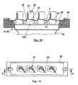
- Figures 10 and 11 illustrate by a front view and a top view the method of ultrasonic peening of the blade roots, FIG. 10 being a sectional view along E in Figure 11.
- a strong shot peening does not significantly increase the roughness of the shot blasted surface 3 must be able to combine on the treated surface impacts of balls 1a with angles of incidence ⁇ close to the perpendicular to this surface 3 and impacts of balls 1b grazing this surface.
- angles of incidence ⁇ close to the perpendicular we mean an angle ⁇ at least equal to 45 °, the effectiveness of the impact being all the better as this angle ⁇ approaches 90 °.
- an angle of incidence ⁇ grazing means an angle ⁇ less than 45 ° and preferably between 15 ° and 30 °.
- the strong shot peening according to the invention also implies a rate called “of recovery” ranging from 120% to 300%, that is to say that the blasting is carried out for a duration T equal to 120% to 300% of the duration T1 necessary to obtain a 98% normal recovery rate, the normal recovery rate being the ratio between the impacted surface and the total surface exposed to shot blasting.
- the balls strike the surface shot blasted with an angle of incidence and a preferred direction, this angle of incidence should be sufficient to pre-stress the blasted surface. Therefore, the bulges forming around the craters are not leveled and tend, on the contrary, to gather in waves clearly visible under the microscope with a magnification x50 to x100, the craters tending to gather more or less in furrows perpendicular to the waves.
- the vane rotor has a rim 10 having a general form of revolution around a geometric axis 11, this rim 10 being bounded radially outwards by a peripheral surface 12 and laterally by two sidewalls 13.
- the rim 10 has at its periphery 12 a plurality of grooves 14 substantially rectilinear called “axial" each comprising a mouth 15 laterally extended by two lateral openings 16, the mouth 15 opening on the periphery 12, the lateral openings 16 opening onto the sides 13.
- the grooves 14 have a substantially trapezoidal profile called "dovetail" with a mouth 15 narrower.
- These grooves 14 may be parallel to the geometric axis 11 or oblique. They can be straight or in an arc.
- a blade 20 successively comprises top to bottom in this figure a thin blade 21, a platform 22 extending laterally on each side of the blade 20 and a foot 23 of substantially shaped trapezoidal and complementary to that of the groove 14.
- the blade 20 is fitted by its foot 23 in the groove 14 with limited play, the foot 23 then being immobilized in the groove 14 by various locking means not shown. Foot 23 arrives at contact of the groove 14 along two contact lines 24 located at the rear of the mouth 15 and set back from this mouth 15.
- the attachment 26 of the blade 20 has the groove 14 and the foot 23.
- the blade rotor has in this second example a rim 10 having a general shape of revolution around an axis geometric 11, this rim 10 being limited radially outward by a surface peripheral 12 annular.
- the rim 10 comprises in this example at the periphery 12 three grooves 14 annular whose descriptions are identical: Each groove annular 14 has a mouth 15 also annular and opening onto the periphery 12. Each groove also has a local opening 18 opening also on the periphery 12, this so-called "local” opening 18.
- Each groove annular 14 has a substantially trapezoidal profile called "dovetail" with a mouth 15 narrower.
- a blade 20 successively comprises top to bottom in this figure a thin blade 21, a platform 22 extending laterally on each side of the blade 20 and a foot 23 of substantially shaped trapezoidal and complementary to that of the groove 14, the foot 23 being in this example arranged transversely to the blade 21.
- This figure also shows for information section 21a of the blade 21.
- the blade 20 is fitted by its foot 23 in the annular groove 14 with limited play and blocked by non-locking means represented.
- Each annular groove 14 thus receives a plurality of blades 20, the foot 23 is introduced through the local opening, referenced 18 in FIG. 6, and brought into position by sliding in the annular groove 14.
- the foot 23 comes into contact with the annular groove 14 along two contact lines 24 also annular and located at the back of the mouth 15.
- attachments 26 of the blades 20 is meant also the annular groove 14 and the feet 23.
- the sonotrode 30 comprises a vibrating surface 31 capable of being introduced into the mouth 15 of the groove 14.
- the sonotrode 30 slides in a sheath 32 with a clearance E less than the diameter balls 1.
- the sealing of the sonotrode 30 balls relative to the mouth 15 may be secured by the scabbard or by any other means. In a preferred mode of However, this sealing is more simply ensured by giving the sonotrode 30 a rectangular section with a width equal to that of the mouth 15 subtracted from a clearance E less than the diameter of the balls 1.
- the sheath 32 supports two ears 33 on either side of the sonotrode 30, these ears being capable of slide in the annular groove 14 with a clearance E less than the diameter of the balls 1. It is understood that the sonotrode 30 and the ears 33 cooperate to contain the balls 1 to inside a portion of the annular groove 14 and against the walls of this groove 14.
- An advantage of the process is to avoid coating with a protective coating of parts of the blade that are not to be shot blasted, i.e. platform 22 and blade 21, this protection provided by the cover, the platform 22 and the blade 21 remaining behind the cover 45 outside the enclosure 40.
- the feet 23 are positioned above the vibrating surface 31 of the sonotrode 30 in order to ensure a homogeneous peening of all the feet 23.
- the vanes 20 comprising a cooling cavity emerging at the base 23a of the foot 23, this base 23a is positioned at a distance of the sonotrode 30 smaller than the diameter of the balls 1 in order to prevent the balls 1 from enter the cooling cavity.
Landscapes
- Engineering & Computer Science (AREA)
- Mechanical Engineering (AREA)
- Chemical & Material Sciences (AREA)
- Materials Engineering (AREA)
- Organic Chemistry (AREA)
- Metallurgy (AREA)
- Crystallography & Structural Chemistry (AREA)
- General Engineering & Computer Science (AREA)
- Turbine Rotor Nozzle Sealing (AREA)
- Grinding And Polishing Of Tertiary Curved Surfaces And Surfaces With Complex Shapes (AREA)
- Laser Beam Processing (AREA)
- Finish Polishing, Edge Sharpening, And Grinding By Specific Grinding Devices (AREA)
- Structures Of Non-Positive Displacement Pumps (AREA)
Abstract
Description
- Brevet EP 0 922 532 paragraphe [0005] colonne 1 lignes 33 à 38. L'une des solutions préconisée est de réduire l'intensité et le taux de recouvrement du grenaillage paragraphe [0006] lignes 39-40. Ce même brevet indique ligne 41 qu'il peut en résulter une réduction de la durée de vie de la pièce.
- Dans le magazine "Souder" n°5 de septembre 1998, l'étude "Le principe du choc laser et ses applications au traitement des matériaux" effectue une comparaison du grenaillage dit "par choc laser" avec le grenaillage conventionnel et indique page 13 avant dernier paragraphe que le grenaillage conventionnel crée des microcratères résultant des impacts des billes et augmentant la rugosité. Selon les exemples donnés par le premier tableau page 14, la rugosité (Ra) d'une surface usinée peut augmenter de 2,3 µm à 5,5 µm après un grenaillage fort.
Un tel procédé est remarquable en ce que le grenaillage est effectué par le procédé dit "par ultrasons", les billes étant projetées par la percussion d'une sonotrode mise en vibration, les billes étant contenues dans une enceinte et formant un brouillard à l'intérieur de enceinte, le constituant à grenailler étant amenée au contact du brouillard de billes,
et en ce que le grenaillage est effectué à un indice Almen au moins égal à F8A.
- le première ligne indique les rugosités (Ra) mesurées avant le grenaillage,
- la seconde ligne indique les rugosités (Ra) mesurées sur ces mêmes surfaces après un grenaillage conventionnel fort d'indice Almen égal à F17A et une mise en précontrainte sous la surface grenaillée atteignant 1000 MPa,
- la troisième ligne indique les rugosités (Ra) mesurées sur ces mêmes surfaces après
un grenaillage par ultrasons équivalent au précédent d'indice Almen égal à F17A avec
une mise en précontrainte sous la surfaces atteignant 1000 MPa,
Surface n°1 (fraisée) Surface n°2 (tournée) Rugosité (Ra) avant le grenaillage 0,27 µm 0,90 µm Rugosité (Ra) après un grenaillage conventionnel, indice Almen = F17A, billes = 0,315 mm. 1,53 µm 1,94 µm Rugosité après un grenaillage US, indice Almen = F17A, billes = 1,5mm 0,47 µm 0,93 µm
- Les billes 1a impactant la surface à grenailler avec un angle α proche de la perpendiculaire à cette surface seront efficaces pour créer aux points d'impacts une précontrainte de compression importante, ces billes laissant cependant sur la surface 3 impactée des cratères 4 entourés de bourrelets 5 formant aspérités.
- A l'inverse, les billes 1b impactant la surface 3 avec un angle β faible, c'est à dire rasant plutôt la surface 3, tendront à niveler les bourrelets 5 et à résorber au moins partiellement les cratères 4, ces billes 1b étant bien évidemment peu ou pas du tout efficaces pour créer une mise en précontrainte de compression suffisante. Ce rôle des billes rasantes est confirmé par le tableau précédent. En effet, la surface n°2 reçoit préférentiellement des billes rasantes car elle est grenaillée par ultrasons dans une position perpendiculaire à la sonotrode, ce qui explique que la rugosité n'augmente sensiblement pas.
- ces billes sont parfaitement sphériques et donnent donc un meilleur état de surface,
- ces billes très dures ne se cassent pas et ne produisent donc pas d'arrêtes vives susceptibles d'altérer l'état de surface de la pièce grenaillée.
Avec un tel dispositif, le procédé de grenaillage par ultrasons des rainures axiales 14 comporte les opérations suivantes :
- disposer la jante 10 au dessus de la sonotrode 30 dans une position appropriée pour amener chaque rainure 14 au dessus de la sonotrode 30 par rotation de la jante 10 selon son axe géométrique 11,
- disposer une dose de billes 1 sur la sonotrode 30, la sonotrode étant de préférence rentrée dans le fourreau 32 afin de constituer au dessus de sa surface vibrante 31 un récipient susceptible de contenir les billes 1,
- faire tourner la jante 10 pour amener successivement chaque rainure 14 au dessus de la sonotrode 30, chaque rainure 14 faisant alors l'objet des opérations suivantes :
- recouvrir les ouvertures 16 avec les oreilles 33 et amener la sonotrode 30 dans l'embouchure 15 de la rainure 14, cette opération se faisant de préférence en remontant simultanément la sonotrode 30 et le fourreau 32 jusqu'à ce que les oreilles 33 recouvrent les ouvertures 16, la sonotrode 30 étant ensuite remontée seule dans l'embouchure 15, ce qui a pour effet simultanément d'amener les billes 1 dans la rainure 14 et de mettre la sonotrode 30 en position de travail,
- effectuer le grenaillage de la rainure 14 par la mise en vibration de la sonotrode 30,
- retirer la sonotrode 30.
- d'améliorer l'homogénéité et l'isotropie du brouillard de bille 1 produit à l'intérieur de la rainure 14, afin de mieux combiner une forte mise en précontrainte et une faible rugosité notamment sur les lignes de contact 24 à l'arrière et en retrait de l'embouchure 15,
- de protéger du grenaillage l'embouchure 15 elle-même, cette embouchure 15 formant aspérités et étant de ce fait susceptible d'être écrasée par les impacts des billes 1.
- disposer la jante 10 au dessus de la sonotrode 30 dans une position appropriée pour faire défiler la rainure annulaire 14 au dessus de la sonotrode 30 par rotation de la jante 10 selon son axe géométrique 11,
- disposer une dose de billes 1 sur la sonotrode 30, la sonotrode étant de préférence rentrée dans le fourreau 32 afin de constituer au dessus de sa surface vibrante 31 un récipient susceptible de contenir les billes 1,
- présenter l'ouverture locale 18 au dessus de la sonotrode 30,
- amener la sonotrode 30 et les deux oreilles 33 dans l'ouverture locale 18, la sonotrode 30 étant au niveau de l'embouchure 15 et dans l'alignement de cette embouchure 15, les deux oreilles 33 étant de part et d'autre de la sonotrode 30 et dans l'alignement de la rainure 14,
- faire tourner la jante 10 et mettre la sonotrode 30 en vibration quand les deux oreilles 33 et la sonotrode 30 sont dans la rainure annulaire 14,
- arrêter la sonotrode 30 dès qu'une oreille 33 ressort dans l'ouverture locale 18,
- arrêter la rotation de la jante 10 quand les deux oreilles 33 et la sonotrode 30 sont dans l'ouverture locale 18.
Avec un tel dispositif, le procédé de grenaillage par ultrasons des pieds 23 des aubes 20 comporte les opérations suivantes :
- introduire une dose de billes 1 dans l'enceinte 40,
- introduire les pieds 23 dans les ouvertures 46 du couvercle 45 et immobiliser les aubes 20 sur le couvercle 45,
- mettre la sonotrode 30 en vibration pour effectuer le grenaillage.
Claims (8)
- Procédé pour augmenter la durée de vie des attaches d'aubes sur un rotor, le rotor comportant une jante (10) à la périphérie (12) de laquelle sont attachées une pluralité d'aubes (20) amovibles, les attaches d'aube étant référencées (26) et comportant deux composants (14,23), l'un des composants (14) étant une rainure en queue d'aronde disposée à la périphérie (12) sur la jante (10), l'autre composant (23) étant un pied disposé sur l'aube (20), le pied (23) étant de forme complémentaire à la rainure (14), le pied (23) étant susceptible d'être emboíté dans la rainure (14) afin de réaliser l'attache de l'aube (26) sur la jante (10), au moins un composant (14,23) étant grenaillée par projection de billes (1) afin de créer à sa surface une précontrainte de compression,
caractérisé en ce que :a) le grenaillage est effectué par le procédé dit "par ultrasons", les billes (1) étant projetées par la percussion d'une sonotrode (30) mise en vibration, les billes (1) étant contenues dans une enceinte (40) et formant un brouillard à l'intérieur de enceinte (40), le constituant (14,23) à grenailler étant amenée au contact du brouillard de billes (1),b) le grenaillage est effectué à un indice Almen au moins égal à F8A. - Procédé selon la revendication 1, caractérisé en ce que les billes (1) ont un diamètre au moins égal à 0,8 mm.
- Procédé selon la revendication 1 ou 2, la pièce étant en matériau du groupe acier, alliage de titane, superalliage base chrome, superalliage base nickel, caractérisé en ce que la mise en précontrainte est au moins de 500 MPa.
- Procédé selon l'une quelconque des revendications 1 à 3 appliqué au grenaillage des rainures (14) axiales, ces rainure axiales (14) étant sensiblement rectilignes et ouvertes à chaque extrémité, les ouvertures latérales ainsi constituées étant référencées (16),
caractérisé en ce qu'on emploie une sonotrode susceptible d'être introduite dans l'embouchure (15) des rainures (14) avec des moyens pour étancher la sonotrode (30) avec l'embouchure (15), ainsi que deux oreilles (33) susceptibles de recouvrir les ouvertures latérales (16) et de les occulter avec un jeu E inférieur au diamètre des billes (1),
et en ce qu'il comporte les opérations suivantes :disposer la jante (10) au dessus de la sonotrode (30) dans une position appropriée pour amener chaque rainure axiale (14) au dessus de la sonotrode (30) par rotation de la jante (10) selon son axe géométrique (11),disposer une dose de billes (1) sur la sonotrode (30),faire tourner la jante (10) pour amener successivement chaque rainure axiale (14) au dessus de la sonotrode (30), chaque rainure axiale (14) faisant alors l'objet des opérations suivantes :recouvrir les ouvertures latérales (16) avec les oreilles (33) et amener la sonotrode (30) dans l'embouchure (15) de la rainure axiale (14),effectuer le grenaillage de la rainure axiale (14) par la mise en vibration de la sonotrode (30),retirer la sonotrode (30). - Procédé selon l'une quelconque des revendications 1 à 3 appliqué au grenaillage d'une rainures (14) annulaire, cette rainure annulaire (14) comportant une ouverture locale (18) permettant de faire passer les pieds (23) des aubes (20),
caractérisé en ce qu'on emploie une sonotrode (30) susceptible d'être introduite dans l'embouchure (15) des rainures annulaires (14) avec des moyens pour étancher la sonotrode (30) avec l'embouchure (15), ainsi que deux oreilles (33) susceptibles de passer dans la rainure annulaire (14) avec un jeu E inférieur au diamètre des billes (1),
et en ce qu'il comporte les opérations suivantes :disposer la jante (10) au dessus de la sonotrode (30) dans une position appropriée pour faire défiler la rainure annulaire (14) au dessus de la sonotrode (30) par rotation de la jante (10) selon son axe géométrique (11),disposer une dose de billes (1) sur la sonotrode (30),présenter l'ouverture locale (18) au dessus de la sonotrode (30),amener la sonotrode (30) et les deux oreilles (33) dans l'ouverture locale (18), la sonotrode (30) étant au niveau de l'embouchure (15) et dans l'alignement de cette embouchure (15), les deux oreilles (33) étant de part et d'autre de la sonotrode (30) et dans l'alignement de la rainure annulaire (14),faire tourner la jante (10) et mettre la sonotrode (30) en vibration quand les deux oreilles (33) et la sonotrode (30) sont dans la rainure annulaire (14),arrêter la sonotrode (30) dès qu'une oreille (33) ressort dans l'ouverture locale (18),arrêter la rotation quand les deux oreilles (33) et la sonotrode (30) sont dans l'ouverture locale 18). - Procédé selon l'une quelconque des revendications 1 à 3 appliqué au grenaillage des pieds d'aubes,
caractérisé en ce qu'on emploie une enceinte (40) dont le fond (41) comporte une ouverture (42) par laquelle passe une sonotrode (30) avec un jeu E inférieur au diamètre des billes (1), l'enceinte (40) étant recouverte par un couvercle (45) mince, le couvercle (45) comportant une pluralité d'ouvertures (46) de forme complémentaire aux pieds (23), la distance entre le couvercle (45) et la sonotrode (30) étant au moins égal à la hauteur des pieds (23),
et en ce que le procédé comporte les opérations suivantes :introduire une dose de billes (1) dans l'enceinte (40),introduire les pieds (23) dans les ouvertures (46) du couvercle (45) et immobiliser les aubes (1),mettre la sonotrode (30) en vibration pour effectuer le grenaillage. - Procédé selon la revendication 7 caractérisé en ce que toutes les aubes (20) sont positionnées au dessus de la surface vibrante (31) de la sonotrode (30).
- Procédé selon la revendication 7, les aubes (20) comportant une cavité de refroidissement débouchant à la base (23a) du pied (23), caractérisé en ce que la base (23a) est positionné à une distance de la sonotrode (30) inférieure au diamètre des billes (1).
Applications Claiming Priority (2)
| Application Number | Priority Date | Filing Date | Title |
|---|---|---|---|
| FR0014767A FR2816538B1 (fr) | 2000-11-16 | 2000-11-16 | Procede pour augmenter la duree de vie des attaches d'aubes sur un rotor |
| FR0014767 | 2000-11-16 |
Publications (2)
| Publication Number | Publication Date |
|---|---|
| EP1207013A1 true EP1207013A1 (fr) | 2002-05-22 |
| EP1207013B1 EP1207013B1 (fr) | 2012-01-11 |
Family
ID=8856529
Family Applications (1)
| Application Number | Title | Priority Date | Filing Date |
|---|---|---|---|
| EP01402916A Expired - Lifetime EP1207013B1 (fr) | 2000-11-16 | 2001-11-14 | Procédé pour augmenter la durée de vie des attaches d'aubes sur un rotor |
Country Status (6)
| Country | Link |
|---|---|
| US (1) | US6536109B2 (fr) |
| EP (1) | EP1207013B1 (fr) |
| JP (1) | JP3974385B2 (fr) |
| CA (1) | CA2363306C (fr) |
| FR (1) | FR2816538B1 (fr) |
| SG (1) | SG114512A1 (fr) |
Cited By (3)
| Publication number | Priority date | Publication date | Assignee | Title |
|---|---|---|---|---|
| WO2007137902A1 (fr) * | 2006-05-26 | 2007-12-06 | Siemens Aktiengesellschaft | Dispositif de projection |
| CN107283119A (zh) * | 2017-05-19 | 2017-10-24 | 航天材料及工艺研究所 | 一种复合材料变截面燕尾盲槽加工方法 |
| US20200055165A1 (en) * | 2016-04-12 | 2020-02-20 | General Electric Company | Apparatus and method for peening of machine components |
Families Citing this family (36)
| Publication number | Priority date | Publication date | Assignee | Title |
|---|---|---|---|---|
| US7028378B2 (en) * | 2000-10-12 | 2006-04-18 | Sonats-Societe Des Nouvelles Applications Des Techniques De Surfaces | Method of shot blasting and a machine for implementing such a method |
| JP3951905B2 (ja) * | 2002-04-25 | 2007-08-01 | 日産自動車株式会社 | 回転子コア用の電磁鋼板形成体、これを用いた永久磁石内蔵型回転電機用回転子、永久磁石内蔵型回転電機、および回転子コア用の電磁鋼板形成体の製造方法 |
| JP4189201B2 (ja) * | 2002-10-30 | 2008-12-03 | 新日本製鐵株式会社 | 鋼材の溶接継手における熱影響部の靭性向上方法 |
| US7399371B2 (en) * | 2004-04-16 | 2008-07-15 | Nippon Steel Corporation | Treatment method for improving fatigue life and long-life metal material treated by using same treatment |
| DE102004029546A1 (de) * | 2004-06-19 | 2006-01-05 | Mtu Aero Engines Gmbh | Verfahren und Vorrichtung zum Oberflächenstrahlen von Gasturbinenschaufeln im Bereich ihrer Schaufelfüße |
| US20060021410A1 (en) * | 2004-07-30 | 2006-02-02 | Sonats-Societe Des Nouvelles Applications Des Techniques De Surfaces | Shot, devices, and installations for ultrasonic peening, and parts treated thereby |
| FR2873609B1 (fr) * | 2004-07-30 | 2008-02-22 | Sonats Soc Des Nouvelles Appli | Projectiles, dispositifs et installations de grenaillage par ultrasons et pieces ainsi traitees |
| DE102004037954A1 (de) | 2004-08-05 | 2006-03-16 | Mtu Aero Engines Gmbh | Vorrichtung zum Oberflächenstrahlen von Bauteilen |
| DE102004059592B4 (de) | 2004-12-10 | 2014-09-04 | MTU Aero Engines AG | Verfahren zum Oberflächenstrahlen von Hohlräumen, insbesondere von Hohlräumen an Gasturbinen |
| US8814861B2 (en) | 2005-05-12 | 2014-08-26 | Innovatech, Llc | Electrosurgical electrode and method of manufacturing same |
| US7147634B2 (en) | 2005-05-12 | 2006-12-12 | Orion Industries, Ltd. | Electrosurgical electrode and method of manufacturing same |
| WO2006124616A2 (fr) * | 2005-05-12 | 2006-11-23 | General Electric Company | Traitement par ecrouissage aux ultrasons de composants assembles |
| FR2889669B1 (fr) * | 2005-08-12 | 2007-11-02 | Snecma | Piece metallique traitee par mise en compression de sous couches. procede pour obtenir une telle piece. |
| DE102005054866A1 (de) * | 2005-11-17 | 2007-05-31 | Mtu Aero Engines Gmbh | Verfahren zum Herstellen von metallischen Bauteilen, insbesondere für Turbomaschinen, mit kleinen Kantenradien |
| US7516547B2 (en) * | 2005-12-21 | 2009-04-14 | General Electric Company | Dovetail surface enhancement for durability |
| DE102006016949A1 (de) * | 2006-04-11 | 2007-10-25 | Mtu Aero Engines Gmbh | Verfahren zum Herstellen eines Bauteils |
| DE102007009470A1 (de) * | 2007-02-27 | 2008-08-28 | Daimler Ag | Verfahren und Vorrichtung zum Oberflächenstrahlen |
| FR2930184B1 (fr) * | 2008-04-18 | 2010-12-31 | Snecma | Procede de grenaillage par ultrason de pieces de turbomachines. |
| JP5218228B2 (ja) * | 2008-04-23 | 2013-06-26 | 新東工業株式会社 | 搬送装置及びブラスト加工装置 |
| US8240042B2 (en) * | 2008-05-12 | 2012-08-14 | Wood Group Heavy Industrial Turbines Ag | Methods of maintaining turbine discs to avert critical bucket attachment dovetail cracks |
| EP2364116B1 (fr) * | 2008-10-23 | 2015-12-23 | Spinewelding AG | Dispositif d'augmentation permettant l'ancrage d'objets dans un tissu dur |
| DE102009021582A1 (de) * | 2009-05-15 | 2010-12-02 | Rolls-Royce Deutschland Ltd & Co Kg | Verfahren zur Oberflächenverfestigung und -glättung von metallischen Bauteilen |
| DE102009040324B4 (de) * | 2009-09-05 | 2016-11-17 | MTU Aero Engines AG | Verfahren zur Wärmebehandlung von Gasturbinenschaufeln |
| US8794925B2 (en) * | 2010-08-24 | 2014-08-05 | United Technologies Corporation | Root region of a blade for a gas turbine engine |
| US20130183157A1 (en) * | 2012-01-17 | 2013-07-18 | Venkatarama K. Seetharaman | Method of surface treatment for dovetail in gas turbine engine fan blade |
| US8959738B2 (en) * | 2012-03-21 | 2015-02-24 | General Electric Company | Process of repairing a component, a repair tool for a component, and a component |
| US10633985B2 (en) * | 2012-06-25 | 2020-04-28 | General Electric Company | System having blade segment with curved mounting geometry |
| US9200521B2 (en) * | 2012-10-30 | 2015-12-01 | General Electric Company | Components with micro cooled coating layer and methods of manufacture |
| US20140255620A1 (en) * | 2013-03-06 | 2014-09-11 | Rolls-Royce Corporation | Sonic grain refinement of laser deposits |
| US10018047B2 (en) * | 2013-12-12 | 2018-07-10 | United Technologies Corporation | Methods of roughing and finishing engine hardware |
| DE102016100663A1 (de) * | 2016-01-15 | 2017-07-20 | Rolls-Royce Deutschland Ltd & Co Kg | Vorrichtung und Verfahren zum Strahlverfestigen von Oberflächenbereichen, insbesondere von Tannenbaumprofilen |
| JP7015468B2 (ja) * | 2018-01-12 | 2022-02-03 | 富士電機株式会社 | 蒸気タービン翼及びその製造方法 |
| DE102018203777A1 (de) * | 2018-03-13 | 2019-09-19 | MTU Aero Engines AG | Nachbehandlungsverfahren für Schaufeln einer Strömungsmaschine |
| CN111843634A (zh) * | 2020-07-28 | 2020-10-30 | 大连理工大学 | 一种石英半球谐振子加工工装及方法 |
| CN117400150B (zh) * | 2020-12-10 | 2026-03-27 | 苏州圣美特压铸科技有限公司 | 工件研磨抛光设备 |
| CN114134300B (zh) * | 2021-12-13 | 2023-12-05 | 中船重工龙江广瀚燃气轮机有限公司 | 一种叶片进排气边喷丸保护装置 |
Citations (6)
| Publication number | Priority date | Publication date | Assignee | Title |
|---|---|---|---|---|
| US4426867A (en) * | 1981-09-10 | 1984-01-24 | United Technologies Corporation | Method of peening airfoils and thin edged workpieces |
| US4888863A (en) | 1988-03-21 | 1989-12-26 | Westinghouse Electric Corp. | Method and apparatus for producing turbine blade roots |
| FR2689431A1 (fr) | 1992-04-06 | 1993-10-08 | Teknoson | Procédé et dispositif notamment de durcissement par ultrasons de pièces métalliques. |
| FR2714629A1 (fr) * | 1993-12-30 | 1995-07-07 | Teknoson Sa | Procédé et dispositif d'ébavurage de pièces mécaniques. |
| FR2743742A1 (fr) | 1996-01-24 | 1997-07-25 | Seb Sa | Procede de traitement d'une surface metallique et de fabrication d'un article culinaire |
| EP1101827A1 (fr) * | 1999-11-18 | 2001-05-23 | Snecma Moteurs | Procédé de grenaillage par ultraons de surfaces annulaires de grandes dimensions sur des pièces minces |
Family Cites Families (12)
| Publication number | Priority date | Publication date | Assignee | Title |
|---|---|---|---|---|
| US3482423A (en) * | 1968-02-26 | 1969-12-09 | Metal Improvement Co | Blade peening masking apparatus |
| US3668913A (en) * | 1970-10-05 | 1972-06-13 | Metal Improvement Co | Apparatus for shot-peening turbine blades |
| US4419875A (en) * | 1981-09-10 | 1983-12-13 | Progressive Blasting Systems, Inc. | Article manipulator mechanism for accelerated shot treating apparatus |
| FR2713974B1 (fr) * | 1993-12-22 | 1996-01-19 | Snecma | Dispositif de grenaillage de surfaces non accessibles par une canalisation droite. |
| FR2715884B1 (fr) * | 1994-02-04 | 1996-04-12 | Gec Alsthom Electromec | Procédé et dispositif pour le traitement de surface et la mise en précontrainte de la paroi intérieure d'une cavité. |
| US5620307A (en) * | 1995-03-06 | 1997-04-15 | General Electric Company | Laser shock peened gas turbine engine blade tip |
| US5735044A (en) * | 1995-12-12 | 1998-04-07 | General Electric Company | Laser shock peening for gas turbine engine weld repair |
| US5813265A (en) | 1997-12-12 | 1998-09-29 | General Electric Company | Balanced electromagnetic peening |
| US5950470A (en) * | 1998-09-09 | 1999-09-14 | United Technologies Corporation | Method and apparatus for peening the internal surface of a non-ferromagnetic hollow part |
| US6170308B1 (en) * | 1999-07-20 | 2001-01-09 | United Technologies Corporation | Method for peening the internal surface of a hollow part |
| FR2801236B1 (fr) | 1999-11-18 | 2001-12-21 | Snecma | Procede et machine de grenaillage par ultrasons de pieces sur une roue |
| US6340500B1 (en) * | 2000-05-11 | 2002-01-22 | General Electric Company | Thermal barrier coating system with improved aluminide bond coat and method therefor |
-
2000
- 2000-11-16 FR FR0014767A patent/FR2816538B1/fr not_active Expired - Lifetime
-
2001
- 2001-11-13 CA CA002363306A patent/CA2363306C/fr not_active Expired - Lifetime
- 2001-11-14 EP EP01402916A patent/EP1207013B1/fr not_active Expired - Lifetime
- 2001-11-15 JP JP2001350517A patent/JP3974385B2/ja not_active Expired - Lifetime
- 2001-11-16 SG SG200107171A patent/SG114512A1/en unknown
- 2001-11-16 US US09/987,860 patent/US6536109B2/en not_active Expired - Lifetime
Patent Citations (6)
| Publication number | Priority date | Publication date | Assignee | Title |
|---|---|---|---|---|
| US4426867A (en) * | 1981-09-10 | 1984-01-24 | United Technologies Corporation | Method of peening airfoils and thin edged workpieces |
| US4888863A (en) | 1988-03-21 | 1989-12-26 | Westinghouse Electric Corp. | Method and apparatus for producing turbine blade roots |
| FR2689431A1 (fr) | 1992-04-06 | 1993-10-08 | Teknoson | Procédé et dispositif notamment de durcissement par ultrasons de pièces métalliques. |
| FR2714629A1 (fr) * | 1993-12-30 | 1995-07-07 | Teknoson Sa | Procédé et dispositif d'ébavurage de pièces mécaniques. |
| FR2743742A1 (fr) | 1996-01-24 | 1997-07-25 | Seb Sa | Procede de traitement d'une surface metallique et de fabrication d'un article culinaire |
| EP1101827A1 (fr) * | 1999-11-18 | 2001-05-23 | Snecma Moteurs | Procédé de grenaillage par ultraons de surfaces annulaires de grandes dimensions sur des pièces minces |
Cited By (6)
| Publication number | Priority date | Publication date | Assignee | Title |
|---|---|---|---|---|
| WO2007137902A1 (fr) * | 2006-05-26 | 2007-12-06 | Siemens Aktiengesellschaft | Dispositif de projection |
| US8578745B2 (en) | 2006-05-26 | 2013-11-12 | Siemens Aktiengesellschaft | Peening device |
| US20200055165A1 (en) * | 2016-04-12 | 2020-02-20 | General Electric Company | Apparatus and method for peening of machine components |
| US11524387B2 (en) * | 2016-04-12 | 2022-12-13 | General Electric Company | Apparatus and method for peening of machine components |
| CN107283119A (zh) * | 2017-05-19 | 2017-10-24 | 航天材料及工艺研究所 | 一种复合材料变截面燕尾盲槽加工方法 |
| CN107283119B (zh) * | 2017-05-19 | 2019-10-22 | 航天材料及工艺研究所 | 一种复合材料变截面燕尾盲槽加工方法 |
Also Published As
| Publication number | Publication date |
|---|---|
| FR2816538B1 (fr) | 2003-01-17 |
| JP3974385B2 (ja) | 2007-09-12 |
| US20020124402A1 (en) | 2002-09-12 |
| CA2363306A1 (fr) | 2002-05-16 |
| JP2002200562A (ja) | 2002-07-16 |
| CA2363306C (fr) | 2008-04-01 |
| EP1207013B1 (fr) | 2012-01-11 |
| FR2816538A1 (fr) | 2002-05-17 |
| SG114512A1 (en) | 2005-09-28 |
| US6536109B2 (en) | 2003-03-25 |
Similar Documents
| Publication | Publication Date | Title |
|---|---|---|
| CA2363306C (fr) | Procede pour augmenter la duree de vie des attaches d'aubes sur un rotor | |
| CA2555113C (fr) | Piece metallique traitee par mise en compression de sous couches, procede pour obtenir une telle piece | |
| CA2392138C (fr) | Grenaillage transversal par ultrasons des aubes sur un rotor | |
| CA2325898C (fr) | Procede et machine de grenaillage par ultrasons de pieces sur une roue | |
| CA2363276C (fr) | Procede et installation de grenaillage par ultrasons des alveoles annulaires d'attache d'aubes sur un rotor | |
| EP1911549B1 (fr) | Masque de protection pour le traitement en surface d'aubes de turbomachines | |
| EP1208942B1 (fr) | Grenaillage des sommets des aubes refroidies | |
| FR2801322A1 (fr) | Procede de grenaillage par ultrasons de surfaces annulaires de grandes dimensions sur des pieces minces | |
| EP2288473B1 (fr) | Procede de grenaillage par ultrasons de pieces de turbomachines | |
| CA2363313C (fr) | Procede et dispositif de grenaillage par ultrasons des alveoles "axiales" d'attache des aubes sur un rotor | |
| EP2255926B1 (fr) | Procédé et dispositif de grenaillage par ultrasons | |
| FR2714629A1 (fr) | Procédé et dispositif d'ébavurage de pièces mécaniques. | |
| WO2008029039A2 (fr) | Dispositif de traitement pour le grenaillage de la surface interieure d'une piece tubulaire | |
| FR2908678A1 (fr) | Procede de grenaillage d'un percage | |
| FR2815281A1 (fr) | Procede de grenaillage et machine pour la mise en oeuvre d'un tel procede | |
| FR3136691A1 (fr) | Outillage de support pour le traitement de surface d’une pièce aéronautique par médias abrasifs |
Legal Events
| Date | Code | Title | Description |
|---|---|---|---|
| PUAI | Public reference made under article 153(3) epc to a published international application that has entered the european phase |
Free format text: ORIGINAL CODE: 0009012 |
|
| 17P | Request for examination filed |
Effective date: 20011123 |
|
| AX | Request for extension of the european patent |
Free format text: AL;LT;LV;MK;RO;SI |
|
| AKX | Designation fees paid |
Designated state(s): DE FR GB IE IT NL |
|
| RAP1 | Party data changed (applicant data changed or rights of an application transferred) |
Owner name: SNECMA SERVICES Owner name: SNECMA |
|
| 111L | Licence recorded |
Free format text: 0101 SONATS Effective date: 20081122 |
|
| 17Q | First examination report despatched |
Effective date: 20090219 |
|
| RAP1 | Party data changed (applicant data changed or rights of an application transferred) |
Owner name: SNECMA |
|
| GRAP | Despatch of communication of intention to grant a patent |
Free format text: ORIGINAL CODE: EPIDOSNIGR1 |
|
| RIN1 | Information on inventor provided before grant (corrected) |
Inventor name: KERNEIS, STEPHANE MICHEL Inventor name: SIMON GUILLAUME, FRANCOIS ROGER Inventor name: FRADIN, WILLY LIONEL Inventor name: NTSAMA-ETOUNDI, MARIE-CHRISTINE MARCELLE Inventor name: HOFFMANN, HAKIM Inventor name: BERTHELET, BENOIT JEAN HENRI Inventor name: CHAREYRE, FRANCIS LUCIEN GUY |
|
| GRAS | Grant fee paid |
Free format text: ORIGINAL CODE: EPIDOSNIGR3 |
|
| RIN1 | Information on inventor provided before grant (corrected) |
Inventor name: NTSAMA-ETOUNDI, MARIE-CHRISTINE MARCELLE Inventor name: FRADIN, WILLY LIONEL Inventor name: CHAREYRE, FRANCIS LUCIEN GUY Inventor name: SIMON, GUILLAUME FRANCOIS ROGER Inventor name: BERTHELET, BENOIT JEAN HENRI Inventor name: HOFFMANN, HAKIM Inventor name: KERNEIS, STEPHANE MICHEL |
|
| GRAA | (expected) grant |
Free format text: ORIGINAL CODE: 0009210 |
|
| AK | Designated contracting states |
Kind code of ref document: B1 Designated state(s): DE FR GB IE IT NL |
|
| REG | Reference to a national code |
Ref country code: GB Ref legal event code: FG4D Free format text: NOT ENGLISH |
|
| REG | Reference to a national code |
Ref country code: IE Ref legal event code: FG4D |
|
| REG | Reference to a national code |
Ref country code: DE Ref legal event code: R096 Ref document number: 60145933 Country of ref document: DE Effective date: 20120308 |
|
| REG | Reference to a national code |
Ref country code: NL Ref legal event code: VDEP Effective date: 20120111 |
|
| PG25 | Lapsed in a contracting state [announced via postgrant information from national office to epo] |
Ref country code: NL Free format text: LAPSE BECAUSE OF FAILURE TO SUBMIT A TRANSLATION OF THE DESCRIPTION OR TO PAY THE FEE WITHIN THE PRESCRIBED TIME-LIMIT Effective date: 20120111 |
|
| REG | Reference to a national code |
Ref country code: IE Ref legal event code: FD4D |
|
| PG25 | Lapsed in a contracting state [announced via postgrant information from national office to epo] |
Ref country code: IE Free format text: LAPSE BECAUSE OF FAILURE TO SUBMIT A TRANSLATION OF THE DESCRIPTION OR TO PAY THE FEE WITHIN THE PRESCRIBED TIME-LIMIT Effective date: 20120111 |
|
| PLBE | No opposition filed within time limit |
Free format text: ORIGINAL CODE: 0009261 |
|
| STAA | Information on the status of an ep patent application or granted ep patent |
Free format text: STATUS: NO OPPOSITION FILED WITHIN TIME LIMIT |
|
| 26N | No opposition filed |
Effective date: 20121012 |
|
| REG | Reference to a national code |
Ref country code: DE Ref legal event code: R097 Ref document number: 60145933 Country of ref document: DE Effective date: 20121012 |
|
| REG | Reference to a national code |
Ref country code: FR Ref legal event code: PLFP Year of fee payment: 15 |
|
| REG | Reference to a national code |
Ref country code: FR Ref legal event code: PLFP Year of fee payment: 16 |
|
| REG | Reference to a national code |
Ref country code: FR Ref legal event code: PLFP Year of fee payment: 17 |
|
| REG | Reference to a national code |
Ref country code: FR Ref legal event code: CD Owner name: SAFRAN AIRCRAFT ENGINES, FR Effective date: 20170717 |
|
| REG | Reference to a national code |
Ref country code: FR Ref legal event code: PLFP Year of fee payment: 18 |
|
| PGFP | Annual fee paid to national office [announced via postgrant information from national office to epo] |
Ref country code: DE Payment date: 20201020 Year of fee payment: 20 Ref country code: IT Payment date: 20201021 Year of fee payment: 20 Ref country code: FR Payment date: 20201021 Year of fee payment: 20 Ref country code: GB Payment date: 20201021 Year of fee payment: 20 |
|
| REG | Reference to a national code |
Ref country code: DE Ref legal event code: R071 Ref document number: 60145933 Country of ref document: DE |
|
| REG | Reference to a national code |
Ref country code: GB Ref legal event code: PE20 Expiry date: 20211113 |
|
| PG25 | Lapsed in a contracting state [announced via postgrant information from national office to epo] |
Ref country code: GB Free format text: LAPSE BECAUSE OF EXPIRATION OF PROTECTION Effective date: 20211113 |