EP2364116B1 - Dispositif d'augmentation permettant l'ancrage d'objets dans un tissu dur - Google Patents
Dispositif d'augmentation permettant l'ancrage d'objets dans un tissu dur Download PDFInfo
- Publication number
- EP2364116B1 EP2364116B1 EP09744313.9A EP09744313A EP2364116B1 EP 2364116 B1 EP2364116 B1 EP 2364116B1 EP 09744313 A EP09744313 A EP 09744313A EP 2364116 B1 EP2364116 B1 EP 2364116B1
- Authority
- EP
- European Patent Office
- Prior art keywords
- augmentation
- tool
- hard tissue
- opening
- contact surface
- Prior art date
- Legal status (The legal status is an assumption and is not a legal conclusion. Google has not performed a legal analysis and makes no representation as to the accuracy of the status listed.)
- Active
Links
- 230000003416 augmentation Effects 0.000 title claims description 188
- 238000004873 anchoring Methods 0.000 title claims description 19
- 239000000463 material Substances 0.000 claims description 107
- 230000010355 oscillation Effects 0.000 claims description 71
- 239000007943 implant Substances 0.000 claims description 45
- 239000012815 thermoplastic material Substances 0.000 claims description 27
- 230000010358 mechanical oscillation Effects 0.000 claims description 16
- 230000003190 augmentative effect Effects 0.000 claims description 13
- 229920001169 thermoplastic Polymers 0.000 claims description 11
- 239000004416 thermosoftening plastic Substances 0.000 claims description 11
- 230000000694 effects Effects 0.000 claims description 8
- 238000002513 implantation Methods 0.000 claims description 6
- 230000014759 maintenance of location Effects 0.000 claims description 4
- 238000003825 pressing Methods 0.000 claims description 3
- 210000001519 tissue Anatomy 0.000 description 55
- 238000000034 method Methods 0.000 description 41
- 210000000988 bone and bone Anatomy 0.000 description 38
- 229920000642 polymer Polymers 0.000 description 8
- 239000000945 filler Substances 0.000 description 7
- 238000002844 melting Methods 0.000 description 7
- 230000008018 melting Effects 0.000 description 7
- 238000003780 insertion Methods 0.000 description 5
- 230000037431 insertion Effects 0.000 description 5
- -1 spongy Substances 0.000 description 5
- 229920000747 poly(lactic acid) Polymers 0.000 description 4
- 229920006324 polyoxymethylene Polymers 0.000 description 4
- 239000011148 porous material Substances 0.000 description 4
- 238000013459 approach Methods 0.000 description 3
- 239000000316 bone substitute Substances 0.000 description 3
- 150000001875 compounds Chemical class 0.000 description 3
- 230000008878 coupling Effects 0.000 description 3
- 238000010168 coupling process Methods 0.000 description 3
- 238000005859 coupling reaction Methods 0.000 description 3
- 238000005520 cutting process Methods 0.000 description 3
- 229920006237 degradable polymer Polymers 0.000 description 3
- 229910052588 hydroxylapatite Inorganic materials 0.000 description 3
- 230000001009 osteoporotic effect Effects 0.000 description 3
- XYJRXVWERLGGKC-UHFFFAOYSA-D pentacalcium;hydroxide;triphosphate Chemical compound [OH-].[Ca+2].[Ca+2].[Ca+2].[Ca+2].[Ca+2].[O-]P([O-])([O-])=O.[O-]P([O-])([O-])=O.[O-]P([O-])([O-])=O XYJRXVWERLGGKC-UHFFFAOYSA-D 0.000 description 3
- 229920002463 poly(p-dioxanone) polymer Polymers 0.000 description 3
- 229920002492 poly(sulfone) Polymers 0.000 description 3
- 229920001610 polycaprolactone Polymers 0.000 description 3
- 229920000515 polycarbonate Polymers 0.000 description 3
- 239000004417 polycarbonate Substances 0.000 description 3
- 239000000622 polydioxanone Substances 0.000 description 3
- 230000005855 radiation Effects 0.000 description 3
- QORWJWZARLRLPR-UHFFFAOYSA-H tricalcium bis(phosphate) Chemical compound [Ca+2].[Ca+2].[Ca+2].[O-]P([O-])([O-])=O.[O-]P([O-])([O-])=O QORWJWZARLRLPR-UHFFFAOYSA-H 0.000 description 3
- 238000003466 welding Methods 0.000 description 3
- VTYYLEPIZMXCLO-UHFFFAOYSA-L Calcium carbonate Chemical compound [Ca+2].[O-]C([O-])=O VTYYLEPIZMXCLO-UHFFFAOYSA-L 0.000 description 2
- AEMRFAOFKBGASW-UHFFFAOYSA-N Glycolic acid Chemical compound OCC(O)=O AEMRFAOFKBGASW-UHFFFAOYSA-N 0.000 description 2
- JVTAAEKCZFNVCJ-REOHCLBHSA-N L-lactic acid Chemical compound C[C@H](O)C(O)=O JVTAAEKCZFNVCJ-REOHCLBHSA-N 0.000 description 2
- 229920002292 Nylon 6 Polymers 0.000 description 2
- 229920002302 Nylon 6,6 Polymers 0.000 description 2
- 239000004696 Poly ether ether ketone Substances 0.000 description 2
- 229920000954 Polyglycolide Polymers 0.000 description 2
- 239000004743 Polypropylene Substances 0.000 description 2
- 230000002411 adverse Effects 0.000 description 2
- JUPQTSLXMOCDHR-UHFFFAOYSA-N benzene-1,4-diol;bis(4-fluorophenyl)methanone Chemical compound OC1=CC=C(O)C=C1.C1=CC(F)=CC=C1C(=O)C1=CC=C(F)C=C1 JUPQTSLXMOCDHR-UHFFFAOYSA-N 0.000 description 2
- 239000005312 bioglass Substances 0.000 description 2
- 239000012620 biological material Substances 0.000 description 2
- 239000002131 composite material Substances 0.000 description 2
- 229920001577 copolymer Polymers 0.000 description 2
- 230000001054 cortical effect Effects 0.000 description 2
- 239000006260 foam Substances 0.000 description 2
- 150000004676 glycans Chemical class 0.000 description 2
- 238000010438 heat treatment Methods 0.000 description 2
- 239000011396 hydraulic cement Substances 0.000 description 2
- 238000011065 in-situ storage Methods 0.000 description 2
- JVTAAEKCZFNVCJ-UHFFFAOYSA-N lactic acid Chemical compound CC(O)C(O)=O JVTAAEKCZFNVCJ-UHFFFAOYSA-N 0.000 description 2
- 238000004519 manufacturing process Methods 0.000 description 2
- 229920001432 poly(L-lactide) Polymers 0.000 description 2
- 239000005014 poly(hydroxyalkanoate) Substances 0.000 description 2
- 229920003229 poly(methyl methacrylate) Polymers 0.000 description 2
- 229920000728 polyester Polymers 0.000 description 2
- 229920002530 polyetherether ketone Polymers 0.000 description 2
- 229920000903 polyhydroxyalkanoate Polymers 0.000 description 2
- 239000004926 polymethyl methacrylate Substances 0.000 description 2
- 229920001155 polypropylene Polymers 0.000 description 2
- 229920001282 polysaccharide Polymers 0.000 description 2
- 239000005017 polysaccharide Substances 0.000 description 2
- 239000004814 polyurethane Substances 0.000 description 2
- 239000001488 sodium phosphate Substances 0.000 description 2
- 235000011008 sodium phosphates Nutrition 0.000 description 2
- GUVRBAGPIYLISA-UHFFFAOYSA-N tantalum atom Chemical compound [Ta] GUVRBAGPIYLISA-UHFFFAOYSA-N 0.000 description 2
- 238000012360 testing method Methods 0.000 description 2
- 230000001225 therapeutic effect Effects 0.000 description 2
- 150000003568 thioethers Chemical class 0.000 description 2
- 238000013519 translation Methods 0.000 description 2
- 230000014616 translation Effects 0.000 description 2
- 235000019731 tricalcium phosphate Nutrition 0.000 description 2
- RYFMWSXOAZQYPI-UHFFFAOYSA-K trisodium phosphate Chemical class [Na+].[Na+].[Na+].[O-]P([O-])([O-])=O RYFMWSXOAZQYPI-UHFFFAOYSA-K 0.000 description 2
- NSMXQKNUPPXBRG-SECBINFHSA-N (R)-lisofylline Chemical compound O=C1N(CCCC[C@H](O)C)C(=O)N(C)C2=C1N(C)C=N2 NSMXQKNUPPXBRG-SECBINFHSA-N 0.000 description 1
- 229920004943 Delrin® Polymers 0.000 description 1
- 206010061218 Inflammation Diseases 0.000 description 1
- 239000004977 Liquid-crystal polymers (LCPs) Substances 0.000 description 1
- 229920000571 Nylon 11 Polymers 0.000 description 1
- 229920000299 Nylon 12 Polymers 0.000 description 1
- 229930040373 Paraformaldehyde Natural products 0.000 description 1
- 229930182556 Polyacetal Natural products 0.000 description 1
- 239000004952 Polyamide Substances 0.000 description 1
- 229920002732 Polyanhydride Polymers 0.000 description 1
- 239000004697 Polyetherimide Substances 0.000 description 1
- 239000004642 Polyimide Substances 0.000 description 1
- 229920000265 Polyparaphenylene Polymers 0.000 description 1
- RTAQQCXQSZGOHL-UHFFFAOYSA-N Titanium Chemical compound [Ti] RTAQQCXQSZGOHL-UHFFFAOYSA-N 0.000 description 1
- 230000002378 acidificating effect Effects 0.000 description 1
- 239000000853 adhesive Substances 0.000 description 1
- 230000001070 adhesive effect Effects 0.000 description 1
- 239000003242 anti bacterial agent Substances 0.000 description 1
- 229940088710 antibiotic agent Drugs 0.000 description 1
- 230000004323 axial length Effects 0.000 description 1
- 230000000975 bioactive effect Effects 0.000 description 1
- 239000000872 buffer Substances 0.000 description 1
- 229910000019 calcium carbonate Inorganic materials 0.000 description 1
- 239000004568 cement Substances 0.000 description 1
- 239000000919 ceramic Substances 0.000 description 1
- 229910010293 ceramic material Inorganic materials 0.000 description 1
- 230000003750 conditioning effect Effects 0.000 description 1
- 238000007796 conventional method Methods 0.000 description 1
- 238000013016 damping Methods 0.000 description 1
- 238000000354 decomposition reaction Methods 0.000 description 1
- 230000007423 decrease Effects 0.000 description 1
- 230000003111 delayed effect Effects 0.000 description 1
- 230000001687 destabilization Effects 0.000 description 1
- OEBRKCOSUFCWJD-UHFFFAOYSA-N dichlorvos Chemical compound COP(=O)(OC)OC=C(Cl)Cl OEBRKCOSUFCWJD-UHFFFAOYSA-N 0.000 description 1
- 238000005553 drilling Methods 0.000 description 1
- 230000005670 electromagnetic radiation Effects 0.000 description 1
- 239000003102 growth factor Substances 0.000 description 1
- 230000035876 healing Effects 0.000 description 1
- 239000000017 hydrogel Substances 0.000 description 1
- 230000004054 inflammatory process Effects 0.000 description 1
- 239000003112 inhibitor Substances 0.000 description 1
- 150000002576 ketones Chemical class 0.000 description 1
- 239000004310 lactic acid Substances 0.000 description 1
- 235000014655 lactic acid Nutrition 0.000 description 1
- JJTUDXZGHPGLLC-UHFFFAOYSA-N lactide Chemical compound CC1OC(=O)C(C)OC1=O JJTUDXZGHPGLLC-UHFFFAOYSA-N 0.000 description 1
- 238000003754 machining Methods 0.000 description 1
- 239000000155 melt Substances 0.000 description 1
- 239000006262 metallic foam Substances 0.000 description 1
- 239000000203 mixture Substances 0.000 description 1
- 238000010883 osseointegration Methods 0.000 description 1
- 230000002093 peripheral effect Effects 0.000 description 1
- 229920003023 plastic Polymers 0.000 description 1
- 239000004033 plastic Substances 0.000 description 1
- 229920001643 poly(ether ketone) Polymers 0.000 description 1
- 229920001606 poly(lactic acid-co-glycolic acid) Polymers 0.000 description 1
- 229920000058 polyacrylate Polymers 0.000 description 1
- 229920002647 polyamide Polymers 0.000 description 1
- 229920000570 polyether Polymers 0.000 description 1
- 229920001601 polyetherimide Polymers 0.000 description 1
- 229920001721 polyimide Polymers 0.000 description 1
- 239000002861 polymer material Substances 0.000 description 1
- 229920000098 polyolefin Polymers 0.000 description 1
- 229920001184 polypeptide Polymers 0.000 description 1
- 229920006389 polyphenyl polymer Polymers 0.000 description 1
- 239000004810 polytetrafluoroethylene Substances 0.000 description 1
- 229920001343 polytetrafluoroethylene Polymers 0.000 description 1
- 229920002635 polyurethane Polymers 0.000 description 1
- 238000001556 precipitation Methods 0.000 description 1
- 102000004196 processed proteins & peptides Human genes 0.000 description 1
- 108090000765 processed proteins & peptides Proteins 0.000 description 1
- 238000012545 processing Methods 0.000 description 1
- 230000008929 regeneration Effects 0.000 description 1
- 238000011069 regeneration method Methods 0.000 description 1
- 230000000717 retained effect Effects 0.000 description 1
- 235000019592 roughness Nutrition 0.000 description 1
- 229910000162 sodium phosphate Inorganic materials 0.000 description 1
- 230000006641 stabilisation Effects 0.000 description 1
- 238000011105 stabilization Methods 0.000 description 1
- 229910001220 stainless steel Inorganic materials 0.000 description 1
- 239000010935 stainless steel Substances 0.000 description 1
- 230000004936 stimulating effect Effects 0.000 description 1
- 239000000126 substance Substances 0.000 description 1
- 229910052715 tantalum Inorganic materials 0.000 description 1
- 239000010936 titanium Substances 0.000 description 1
- 229910052719 titanium Inorganic materials 0.000 description 1
- 238000012546 transfer Methods 0.000 description 1
- 238000002604 ultrasonography Methods 0.000 description 1
Images
Classifications
-
- A—HUMAN NECESSITIES
- A61—MEDICAL OR VETERINARY SCIENCE; HYGIENE
- A61B—DIAGNOSIS; SURGERY; IDENTIFICATION
- A61B17/00—Surgical instruments, devices or methods, e.g. tourniquets
- A61B17/56—Surgical instruments or methods for treatment of bones or joints; Devices specially adapted therefor
- A61B17/58—Surgical instruments or methods for treatment of bones or joints; Devices specially adapted therefor for osteosynthesis, e.g. bone plates, screws, setting implements or the like
- A61B17/68—Internal fixation devices, including fasteners and spinal fixators, even if a part thereof projects from the skin
- A61B17/686—Plugs, i.e. elements forming interface between bone hole and implant or fastener, e.g. screw
-
- A—HUMAN NECESSITIES
- A61—MEDICAL OR VETERINARY SCIENCE; HYGIENE
- A61B—DIAGNOSIS; SURGERY; IDENTIFICATION
- A61B17/00—Surgical instruments, devices or methods, e.g. tourniquets
- A61B17/56—Surgical instruments or methods for treatment of bones or joints; Devices specially adapted therefor
- A61B17/58—Surgical instruments or methods for treatment of bones or joints; Devices specially adapted therefor for osteosynthesis, e.g. bone plates, screws, setting implements or the like
- A61B17/88—Osteosynthesis instruments; Methods or means for implanting or extracting internal or external fixation devices
- A61B17/8802—Equipment for handling bone cement or other fluid fillers
- A61B17/8805—Equipment for handling bone cement or other fluid fillers for introducing fluid filler into bone or extracting it
- A61B17/8822—Equipment for handling bone cement or other fluid fillers for introducing fluid filler into bone or extracting it characterised by means facilitating expulsion of fluid from the introducer, e.g. a screw pump plunger, hydraulic force transmissions, application of vibrations or a vacuum
-
- A—HUMAN NECESSITIES
- A61—MEDICAL OR VETERINARY SCIENCE; HYGIENE
- A61B—DIAGNOSIS; SURGERY; IDENTIFICATION
- A61B17/00—Surgical instruments, devices or methods, e.g. tourniquets
- A61B2017/00004—(bio)absorbable, (bio)resorbable or resorptive
-
- A—HUMAN NECESSITIES
- A61—MEDICAL OR VETERINARY SCIENCE; HYGIENE
- A61B—DIAGNOSIS; SURGERY; IDENTIFICATION
- A61B17/00—Surgical instruments, devices or methods, e.g. tourniquets
- A61B2017/00831—Material properties
- A61B2017/00955—Material properties thermoplastic
-
- A—HUMAN NECESSITIES
- A61—MEDICAL OR VETERINARY SCIENCE; HYGIENE
- A61F—FILTERS IMPLANTABLE INTO BLOOD VESSELS; PROSTHESES; DEVICES PROVIDING PATENCY TO, OR PREVENTING COLLAPSING OF, TUBULAR STRUCTURES OF THE BODY, e.g. STENTS; ORTHOPAEDIC, NURSING OR CONTRACEPTIVE DEVICES; FOMENTATION; TREATMENT OR PROTECTION OF EYES OR EARS; BANDAGES, DRESSINGS OR ABSORBENT PADS; FIRST-AID KITS
- A61F2/00—Filters implantable into blood vessels; Prostheses, i.e. artificial substitutes or replacements for parts of the body; Appliances for connecting them with the body; Devices providing patency to, or preventing collapsing of, tubular structures of the body, e.g. stents
- A61F2/02—Prostheses implantable into the body
- A61F2/28—Bones
- A61F2002/2835—Bone graft implants for filling a bony defect or an endoprosthesis cavity, e.g. by synthetic material or biological material
- A61F2002/2839—Bone plugs or bone graft dowels
-
- A—HUMAN NECESSITIES
- A61—MEDICAL OR VETERINARY SCIENCE; HYGIENE
- A61F—FILTERS IMPLANTABLE INTO BLOOD VESSELS; PROSTHESES; DEVICES PROVIDING PATENCY TO, OR PREVENTING COLLAPSING OF, TUBULAR STRUCTURES OF THE BODY, e.g. STENTS; ORTHOPAEDIC, NURSING OR CONTRACEPTIVE DEVICES; FOMENTATION; TREATMENT OR PROTECTION OF EYES OR EARS; BANDAGES, DRESSINGS OR ABSORBENT PADS; FIRST-AID KITS
- A61F2/00—Filters implantable into blood vessels; Prostheses, i.e. artificial substitutes or replacements for parts of the body; Appliances for connecting them with the body; Devices providing patency to, or preventing collapsing of, tubular structures of the body, e.g. stents
- A61F2/02—Prostheses implantable into the body
- A61F2/30—Joints
- A61F2002/30001—Additional features of subject-matter classified in A61F2/28, A61F2/30 and subgroups thereof
- A61F2002/30003—Material related properties of the prosthesis or of a coating on the prosthesis
- A61F2002/3006—Properties of materials and coating materials
- A61F2002/30065—Properties of materials and coating materials thermoplastic, i.e. softening or fusing when heated, and hardening and becoming rigid again when cooled
-
- A—HUMAN NECESSITIES
- A61—MEDICAL OR VETERINARY SCIENCE; HYGIENE
- A61F—FILTERS IMPLANTABLE INTO BLOOD VESSELS; PROSTHESES; DEVICES PROVIDING PATENCY TO, OR PREVENTING COLLAPSING OF, TUBULAR STRUCTURES OF THE BODY, e.g. STENTS; ORTHOPAEDIC, NURSING OR CONTRACEPTIVE DEVICES; FOMENTATION; TREATMENT OR PROTECTION OF EYES OR EARS; BANDAGES, DRESSINGS OR ABSORBENT PADS; FIRST-AID KITS
- A61F2210/00—Particular material properties of prostheses classified in groups A61F2/00 - A61F2/26 or A61F2/82 or A61F9/00 or A61F11/00 or subgroups thereof
- A61F2210/0071—Particular material properties of prostheses classified in groups A61F2/00 - A61F2/26 or A61F2/82 or A61F9/00 or A61F11/00 or subgroups thereof thermoplastic
Definitions
- the invention is in the field of anchoring objects in hard tissue and/or hard tissue replacement material, such as bone. Especially, it is suited for anchoring objects in weak or brittle hard tissue, such as osteoporotic bone.
- any load acting on the screw is passed over to only few trabeculae, with adverse consequences both for the load bearing capability of the screw-bone connection and for its long-time stability. This is especially severe in osteoporotic or otherwise weakened bone tissue.
- WO 2008/034277 discloses implants suitable for being anchored with the aid of mechanical vibration in an opening in bone tissue.
- the claimed device is suitable for a method of anchoring an implant in hard tissue and/or hard tissue replacement material, the method comprising the steps of providing an initial opening in the hard tissue and/or hard tissue replacement material, of providing a thermoplastic augmentation element, a tool and a counter element, of compressing the augmentation element between the tool and the counter element while energy is coupled into the tool and/or the augmentation element and while a periphery of a liquefaction interface of the oscillation tool and the augmentation element and/or of a liquefaction interface of the augmentation element and the counter element is in the opening, thereby liquefying material of the augmentation element at the liquefaction interface(s) to yield liquefied material, causing portions of the liquefied material to penetrate into structures of the hard tissue and/or hard tissue replacement material or connected thereto, allowing the liquefied material to harden and to thereby become augmentation material, removing the oscillation tool and the counter element, and anchoring the implant in the opening comprising at least some of the augmentation
- the tool is an oscillation tool
- the step of coupling energy into the tool and/or the augmentation element comprises coupling mechanical oscillations into the oscillation tool.
- the material is caused to liquefy at the interface due to external and/or internal friction.
- the structures may be structures of a circumferential wall of the opening if the opening is a bore-like structure.
- the structures may include the structures of trabeculae with spaces between them.
- the structures may include structures of the cortical bone.
- the structures may also be an opening with a circumferential wall that does not surround the interface without any interruption, but that for example is a gap of a joint.
- the structures may be structures of a device connected to the hard tissue and/or hard tissue replacement material.
- pedicle screws for spine stabilization devices have become known, which pedicle screws comprise a radially expandable segment or element.
- the expandable segment or element expands within the cancellous bone during the surgical implantation and creates a channel with a porous wall that allows interdigitation for example by cement.
- the approach described herein allows to fill the channel and the porous wall of the element/segment by thermoplastic material from within the device.
- the interface between the tool and the augmentation element (and/or, as the case may be, between tool and counter element) where liquefying takes place defines a liquefaction interface (or, if liquefaction takes place at the two interfaces, define two liquefaction interfaces).
- the interface between the tool and the augmentation element is the liquefaction interface.
- the system may as an alternative be designed so that the liquefaction interface is the interface between the counter element and the augmentation element (solely or in addition to the interface between the tool and the augmentation element).
- the augmentation element comprises special shape - for example it may be substantially thinner at the interface to the counter element, so that the oscillations may be transmitted through the augmentation element towards the counter element, and also the interface between the counter element and the augmentation element may be the liquefaction interface.
- the steps of allowing the liquefied material to harden and of removing the tool and the counter element may be carried out one after the other in arbitrary sequence, or may be carried out simultaneously.
- the augmentation material is caused to augment an extended part of the circumferential surface, i.e. has a substantial axial extension.
- the augmentation process includes moving the liquefaction interface(s) or at least one liquefaction interface in an axial direction while the energy impinges (i.e. for example while the oscillations act). In such a situation, the hardening in one region may have taken place while in an other region, at an axial distance from the one region, the liquefaction may still take place.
- the augmentation process can be repeated several times, so that over the length of the opening several desired spots are augmented.
- an augmentation may be carried out distally within the vertebral body, medially in the region of the pedicle, and maybe even proximally for the enforcement of the proximal lamina.
- the liquefied material flows usually radially outward into the structures of the hard tissue and/or hard tissue replacement material (or, as the case may be, of the device connected thereto).
- a periphery of the liquefaction interface forms a part of the peripheral interface of the tool - augmentation-element - counter-element assembly.
- the structures of the hard tissue and/or hard tissue replacement material may be a porous structure made up of spaces between trabeculae or similar. They may also be artificially added or naturally occurring roughnesses or the like. Almost any structure that deviates from an even surface is suitable, however, structures with 'undercut' like features are preferable.
- a first special class of hard tissue/hard tissue replacement material suitable to be augmented by the method of using the device according to the invention is trabecular bone, for example osteopenic or osteoporotic bone.
- a second special class of hard tissue/hard tissue replacement material where the invention is especially useful is spongy bone substitute material such as autograft or allograft bone tissue (including cadaver bone material), trabecular metal (especially titanium foam or tantalum foam), or hydraulic cement such as used for vertebroplasty.
- the approach according to the invention thus allows to use, as hard tissue replacement material, spongy, porous material that is highly suitable for ingrowth of real bone material, and to nevertheless soundly anchor the implant in it.
- the opening in the hard tissue and/or hard tissue replacement material may be a blind hole, a gap (of a joint or the like) or a through opening
- the removal of both, the tool and the counter element in many embodiments has to take place to one and the same side, namely to the proximal side.
- the cross sectional area of the final opening will thus at least be equal to the cross sectional area of the most distal portion of the oscillation tool or the counter element, respectively.
- This distal portion is the portion that serves for compressing the augmentation element during the liquefaction of the thermoplastic material.
- the whole augmentation element (or at least a whole axial section of it) has to be completely displaced outwardly from its initial position.
- the augmentation element is tube shaped or has the shape of a plurality of connected or unconnected tube sectors, an inner diameter of the final opening will thus be greater than an average diameter of the augmentation element before the augmentation process.
- the augmentation material during the augmentation process is displaced from an initial, inner position to a final, outer position, by at least a radial distance that corresponds to half a wall thickness of the tube wall of the augmentation element.
- an inner diameter of the augmentation material remaining anchored in the hard tissue and/or hard tissue replacement material after the augmentation process may even be larger than an outer diameter of the augmentation element prior to the augmentation process.
- an entire cross section of the augmentation element is liquefied.
- the liquefaction interface to this purpose covers, in a projection along a movement axis that may also be an opening axis, an entire cross section of the augmentation element.
- the liquefaction step therefore includes continuously melting away, at the liquefaction interface an entire cross section of the augmentation element and displacing it outwardly into and onto the structures of the opening, while the liquefaction interface moves with respect to the counter element (and/or to the tool) and to the body of the remaining augmentation element to continuously 'eat away' the remaining augmentation element.
- the process may, according to a preferably variant, be continued until the tool contact surface and the counter element contact surface contact each other, so that the augmentation element is fully displaced ('used up'). However, it is also possible to stop the process and to remove remaining augmentation element portions together with and between the tool and the counter element.
- the liquefaction interface is the interface between the tool and the augmentation element
- not only the liquefaction interface is subject to an axial movement, but also the interface between the augmentation element and the counter element. Then, an overall length of the augmentation material is shorter than an initial length of the augmentation element.
- the tool contact surface is at a distal end of the augmentation element, and the force for compressing the augmentation element is coupled into the tool as a tensile force - the tool is pulled.
- the tool may comprise a shaft portion and a distal broadening, a rearward (i.e. towards the proximal side) facing surface forming the tool contact surface.
- the counter element then is a "pusher" that may be moved forward (towards the distal side) during the liquefaction step, or that may be held still, depending on how much augmentation material per axial length unit is to be disposed.
- the counter element may for example be of a rigid material with a tube shaped end forming the counter element contact surface. It is in any case preferred if the counter element can optionally be pushed forward and into the opening during the process. If, however, the counter element is not to be moved forward, it may also have the shape of a plate to be held against the hard tissue and/or hard tissue replacement material surface, or similar.
- This "retro" configuration features the advantage of providing maximum flexibility while keeping the contact surfaces between the tool and the sensitive tissue surface at a minimum.
- the tool contact surface is at a proximal end of the augmentation element, and the force for compressing the augmentation element is coupled into the tool as a pressing force - the tool is pushed.
- the counter element that reaches to the distal side and may comprise a shaft portion and a distal broadening with a rearward facing surface forming the counter element contact surface.
- the tool may in addition to the augmentation process serve a different purpose.
- the tool may also be used for creating or expanding the opening in the hard tissue/hard tissue replacement material by means of a cutter and/or chisel like function by having, on a distal side, appropriate shapes.
- Such cutter and/or chisel like functions are as such known from ultrasound processing/machining of bone and tooth material.
- the augmentation element may comprise an axially throughgoing, for example central, opening for the tool (for the retro configuration) or for the counter element (for the forward configuration).
- the axis of the central opening which is preferably parallel to the movement axis and to the opening axis.
- the augmentation element may for example be essentially tube shaped or comprise one or a plurality of sections (sectors) covering different angle ranges (the sectors, by their arrangement defining the central opening). It may, however, also be configured differently and for example comprise helical structures or the like.
- the implant may be a fastening device for fastening other objects to the tissue or for fastening tissue parts to each other.
- the implant as an alternative may also serve as any kind of prosthesis.
- anchoring structures of the implant are brought in intimate contact with the thermoplastic augmentation material.
- the intimate contact may be such as to cause a mechanical anchoring, such as a positive-fit anchoring, and/or such as to cause an anchoring by bonding.
- the implant to be anchored in the opening may therefore, according to a first embodiment of the invention comprise fastening and/or retention structures for a mechanical connection (mechanical anchoring), for example by a positive fit connection.
- fastening and/or retention structures are a thread, a barbed structure, rivet-kind structures etc.
- These structures are preferably such as to engage into the augmented hard tissue and/or hard tissue replacement material, i.e. with reference to a hole axis of the initial hole, they reach further out than the hole radius.
- the implant to be implanted may comprise surface material portions that may be bonded (positively bonded, substance-to-substance bonded; adhesive bonded) to the augmentation material, for example by welding.
- the implant may comprise a threaded section and act as screw.
- the thread of the screw then engages into the hard tissue and/or hard tissue replacement material augmented by the augmentation material.
- the screw diameter in this situation is chosen so that an outer diameter of the threaded section is greater than a diameter of the initial opening.
- the augmented hard tissue and/or hard tissue replacement material may produce a substantial resistance against introduction of the threaded section.
- the tool (and/or potentially the counter element) may comprise structures for conditioning the augmentation material to ease introduction of a thread.
- the tool may comprise radially protruding blades confining the flow of the liquefied thermoplastic material to certain azimuthal angles. Thereby the augmentation material obtains a slitted structure that offers less resistance to radial expansion by an element introduced into the opening.
- the tool may comprise a rotatably mounted thread cutting section to directly cut a thread during the augmentation process.
- the implant may be formed as for example described in WO 02/069 817 , WO 2004/017 857 , WO 2005/079 696 , WO 2008/034 277 , or US provisional patent application 60/983,791 . All these references teach to liquefy thermoplastic material by mechanical oscillations and to cause liquefied thermoplastic material to penetrate into porous structures of the tissue they are to be anchored in. When used in combination with the approach according to the invention, however, the thermoplastic material of the implant will at least partially be welded together with the augmentation material, instead of or in addition to forming a positive-fit connection.
- thermoplastic material is melted only locally at surface portions, for example at the places of energy directors.
- the overall heat impact is substantially lower, and the use of thermoplastic materials with melting temperatures substantially above 37°C is readily possible.
- the invention does not exclude the welding by other means, such as by thermal heating, especially if the implant is very small, at places where the heat impact does not produce extensive damages and/or if the melting temperature of the thermoplastic augmentation materials and/or the thermoplastic implant material is not far above 37°C.
- the thermoplastic material of the augmentation element may be homogeneous or made up of different components (such as of an inner and an outer layer of different hardness).
- the thermoplastic material may be non-resorbable or may be at least partly resorbable. If the primary stability provided by the augmentation material is to be retained, the thermoplastic material is not resorbable or only partly resorbable.
- Suitable Resorbable polymers are e.g. based on lactic acid and/or glycolic acid (PLA, PLLA, PGA, PLGA etc.) or polyhydroxyalkanoates (PHA), polycaprolactones (PCL), polysaccharides, polydioxanones (PD), polyanhydrides, polypeptides or corresponding copolymers or blended polymers or composite materials containing the mentioned polymers as components are suitable as resorbable liquefiable materials.
- PLA lactic acid and/or glycolic acid
- PHA polyhydroxyalkanoates
- PCL polycaprolactones
- PD polysaccharides
- PD polydioxanones
- polyanhydrides polypeptides or corresponding copolymers or blended polymers or composite materials containing the mentioned polymers as components are suitable as resorbable liquefiable materials.
- Thermoplastics such as for example polyolefins, polyacrylates, polymetacrylates, polycarbonates, polyamides, polyesters, polyurethanes, polysulphones, polyaryl ketones, polyimides, polyphenyl sulphides or liquid crystal polymers (LCPS), polyacetals, halogenated polymers, in particular halogenated polyoelefins, polyphenylene sulphides, polysulphones, polyethers, polypropylene (PP), or corresponding copolymers or blended polymers or composite materials containing the mentioned polymers as components are suitable as non-resorbable polymers.
- LCPS liquid crystal polymers
- halogenated polymers in particular halogenated polyoelefins, polyphenylene sulphides, polysulphones, polyethers, polypropylene (PP), or corresponding copolymers or blended polymers or composite materials containing the mentioned polymers as components are suitable as non-resorbable polymers.
- degradable materials are Polylactides like LR706 PLDLLA 70/30, R208 PLDLA 50/50, L210S, and PLLA 100% L, all of Bschreibinger.
- a list of suitable degradable polymer materials can also be found in: Erich Wintermantel und Suk-Woo Haa, "Medizinaltechnik mit biokompatiblen réelle und Maschinen", 3. Auflage, Springer, Berlin 2002 (in the following referred to as "Wintermantel"), page 200; for information on PGA and PLA see pages 202 ff., on PCL see page 207, on PHB/PHV copolymers page 206; on polydioxanone PDS page 209. Discussion of a further bioresorbable material can for example be found in CA Bailey et al., J Hand Surg [Br] 2006 Apr;31(2):208-12 .
- non-degradable materials are: Polyetherketone (PEEK Optima, Grades 450 and 150, Invibio Ltd), Polyetherimide, Polyamide 12, Polyamide 11, Polyamide 6, Polyamide 66, Polycarbonate, Polymethylmethacrylate, Polyoxymethylene.
- PEEK Optima Grades 450 and 150, Invibio Ltd
- Polyetherimide Polyamide 12, Polyamide 11, Polyamide 6, Polyamide 66, Polycarbonate, Polymethylmethacrylate, Polyoxymethylene.
- An overview table of polymers and applications is listed in Wintermantel, page 150; specific examples can be found in Wintermantel page 161 ff. (PE, Hostalen Gur 812, absolute AG), pages 164 ff. (PET) 169ff. (PA, namely PA 6 and PA 66), 171 ff. (PTFE), 173 ff. (PMMA), 180 (PUR, see table), 186 ff. (PEEK), 189 ff. (PSU), 191 f
- thermoplastic material examples include polylactides such as any one of the products LR708 (amorphous Poly-L-DL lactide 70/30), L209 or L210S by Bschreibinger Ingelheim or polycarbonates.
- the liquefiable material having thermoplastic properties may contain foreign phases or compounds serving further functions.
- the thermoplastic material may be strengthened by admixed fillers, for example particulate fillers that may have a therapeutic or other desired effect.
- the thermoplastic material may also contain components which expand or dissolve (create pores) in situ (e.g. polyesters, polysaccharides, hydrogels, sodium phosphates) or compounds to be released in situ and having a therapeutic effect, e.g. promotion of healing and regeneration (e.g. growth factors, antibiotics, inflammation inhibitors or buffers such as sodium phosphate or calcium carbonate against adverse effects of acidic decomposition). If the thermoplastic material is resorbable, release of such compounds is delayed.
- Fillers used may include degradable, osseostimulative fillers to be used in degradable polymers, including: ⁇ -Tricalciumphosphate (TCP), Hydroxyapatite (HA, ⁇ 90% crystallinity; or mixtures of TCP, HA, DHCP, Bioglasses (see Wintermantel).
- Osseo-integration stimulating fillers that are only partially or hardly degradable, for non degradable polymers include: Bioglasses, Hydroxyapatite (>90% cristallinity), HAPEX®, see SM Rea et al., J Mater Sci Mater Med. 2004 Sept;15(9):997-1005 ; for hydroxyapatite see also L.
- Particulate filler types include: coarse type: 5-20 ⁇ m (contents, preferentially 10-25% by volume), sub-micron (nanofillers as from precipitation, preferentially plate like aspect ratio > 10, 10-50 nm, contents 0.5 to 5% by volume).
- More generally liquefaction is achieved by using materials with thermoplastic properties having a melting temperature of up to about 350°C.
- the energy is a mechanical oscillation energy and the tool is an oscillation tool if the liquefaction interface or one of the liquefaction interfaces is between the augmentation element and the counter element
- the modulus of elasticity should be at least 0.5 GPa so that the thermoplastic material transmits the mechanical oscillation with such little damping that inner liquefaction and thus destabilization of the augmentation element does not occur, i.e. liquefaction occurs only where the liquefiable material is at the liquefaction interface.
- the material may in principle also have a lower modulus of elasticity. However, due to the load bearing function the material has, also in this situation a modulus of elasticity should of at least 0.5 GPa is preferred.
- the mechanical oscillations applied have of a frequency preferably in the rage of between 2 and 200 kHz (preferably ultrasonic vibration).
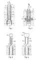
- the device shown in Figure 1 is illustrated partly inserted in an opening in bone tissue 1.
- the opening preferably is translation symmetrical with respect to translations parallel to an axis 2 but may have any cross section perpendicular to that axis.
- the opening has the shape of a circular cylinder, i.e. the cross section is circular.
- the opening 1.1 may have been added to the bone tissue by a conventional method, such as by drilling.
- the device parts as far as to be inserted in the opening 1.1, have are rotational symmetric if the opening is circular in cross section. They comprise an oscillation tool 3, an augmentation element 4, and a counter element 5.
- the augmentation element 4 is formed as a tube of a suitable thermoplastic material.
- the oscillation tool 3 may be metallic and comprises a tool shaft 3.1 reaching through the augmentation element 4 from a proximal side to a distal side.
- the oscillation tool comprises means (not illustrated) for the tool to be coupled to an oscillation generator, such as an ultrasonic device.
- the means are such that a tensile force may be coupled into the oscillation tool.
- the tool comprises a distal broadening 3.2 joined to the shaft 3.1.
- the distal broadening has the shape of a wedge tapering from the distal to the proximal side where it is attached to the shaft.
- the backward-facing surface 3.3 (i.e. the tapering surface facing towards the proximal side) of the distal broadening 3.2 serves as oscillation tool contact surface and oscillation tool coupling-out surface when in contact with a distal first contact surface 4.1 of the augmentation element. Together, the oscillation tool contact surface 3.3 and the augmentation element first contact surface 4.1 form the liquefaction interface.
- the proximal end surface of the augmentation element forms the second augmentation element contact surface 4.2 against which the counter element contact surface 5.1 can be pressed during augmentation.
- the counter element 5 is tube shaped with a wall thickness preferably equal to or greater than the wall shape of the augmentation element.
- the counter element may be metallic or of a suitable plastic or ceramic material.
- thermoplastic material melts at the liquefaction interface. While liquefaction progressively continues at the liquefaction interface, the oscillation tool is pulled towards the proximal side, and/or the counter element is pushed towards the distal side, so that the length of the remaining, not yet molten augmentation element portion gradually decreases.
- the melted augmentation material is pushed sideways into the structures such as openings, and/or pores of the bone material around the circumferential wall of the opening 1.1.
- the augmentation material forms an augmentation zone 6 in the bone tissue around the opening where the bone material is interpenetrated by the again hardened thermoplastic augmentation material.
- the cross section of the remaining final opening may, depending on the cross section of the distal broadening of the oscillation tool, be approximately equal to the cross section of the initial opening, or slightly less than that.
- the length (measured along the axis 2) of the augmentation zone 6 may be approximately equal as the initial length of the augmentation element 4, or it may be less than that, depending on whether the counter element 5 is held still during the augmentation process (then the length will be equal) or whether the counter element is pushed forward during the augmentation process (then the length will be smaller, and the material in the augmentation zone 6 per length unit will be greater than the initial material per length unit of the augmentation element.
- Figure 2 depicts a variant of the device and method of Fig. 1 .
- the distal broadening on the rearward side comprises a face (forming the oscillation tool contact surface) that tapers inward, i.e. that defines a concave structure.
- the inclination with respect to an axis normal plane may for example be between 10° and 60°, especially around 45°.
- Such inward tapering has been found to be especially advantageous in terms of melting properties: it prevents the augmentation element from merely being softened, pushed outward and put over the distal broadening without being properly liquefied. Rather, it centers the augmentation element with respect to the oscillation tool and ensures thorough liquefaction at the liquefaction interface.
- the device as depicted in Fig. 2 can be used like the one of Fig. 1 and be pulled through the opening 1.1 to leave an axially extended augmentation zone of desired length, as discussed above.
- Fig. 2 shows, as second difference to Fig. 1 , the concept of reduced length of the augmentation zone 6 being taken to an extreme: the oscillation tool is held still during the augmentation process, so that the entire axial movement in the augmentation process stems from the forward movement of the counter element 5. This results in a ring-shaped (instead of tube-shaped) augmentation zone 6.
- a set-up as the one illustrated in Figure 1 or 2 may also be used if the energy is coupled into the system by way of rotation of the tool 3.
- the augmentation element may stick to the surface of the counter element, and/or the augmentation element and the counter element may comprise interdigitating structures. Friction then causes the augmentation element to melt at the interface between the augmentation element 4 and the tool 3. If, in contrast, the augmentation element is rotationally coupled to the tool and decoupled from the counter element, the liquefaction will take place at the interface between the augmentation element and the counter element.
- Figure 3 illustrates the anchoring of an implant 11 in the opening 1.1 augmented by the augmentation zone 6.
- the major diameter of the threaded section 11.1 of the screw is greater than the diameter of the initial opening 1.1 so that the thread engages into the bone material in the region of the augmentation zone.
- the augmentation material of the augmentation zone helps to distribute the mechanical load in the bone material and prevents single trabeculae from being loaded too heavily.
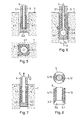
- FIG. 4 depicts an alternative embodiment that, in contrast to the embodiment of Fig. 3 , is also suitable for openings 1.1 with non-circular cross sections.
- the implant 11 comprises a surface or surface regions of thermoplastic material 13.
- the implant may for example consist entirely of the thermoplastic material or may be, as depicted, a hybrid implant with a for example metallic or ceramic core and thermoplastic surface portions. If the implant is a hybrid implant, the thermoplastic surface portions may entirely cover a circumferential surface of an anchoring portion 11.3 to be anchored in the bone tissue or only portions thereof, as for example taught in embodiments of WO2004/017857 .
- the implant 11 further comprises a coupling-in surface 11.5 suitable for a sonotrode to engage to couple mechanical oscillations into the implant.
- the implant is pushed into the opening at least to a certain extent, and then mechanical oscillations are coupled into it, while the implant may optionally be further pushed into the opening. Due to the effect of the mechanical oscillations and the frictional forces created at the periphery of the anchoring portion 11.3, the thermoplastic material 13 starts melting and welds to the augmentation material of the augmentation zone. Optionally, in addition portions 13 of the thermoplastic material may be pushed into structures of the bone material so that an additional anchoring of the kind taught in WO02/069817 is achieved.
- thermoplastic material 13 of the implant 11 of figure 4 does not need to surround the implant shaft.
- the cross section of the implant need not be circular, also in cases where the opening is circular (and the implant then may comprise self-reaming structures).
- the thermoplastic material may in an embodiment cover the bridge portion of the double T only.
- the rigidity of the augmentation material may cause the required force for insertion of the implant to be rather high.
- Figures 5 and 6 depict measures for reducing this force.
- Figure 5 depicts an other embodiment of a device according to the invention.
- the lower panel shows a cross section trough the device in the region of its distal end.
- the oscillation tool 3 depicted in Figure 5 comprises several laterally protruding wing structures 3.7 (or blades). These wing structures prevent the augmentation material from flowing to certain angles and in addition may be sharpened so as to cut through already-hardened augmentation material as well as through bone tissue.
- the wing structures radially protrude into the bone tissue, and axially project further to the distal side than the periphery of the liquefaction interface, so as to sustainably prevent liquefied material from flowing to the angles to be kept free from augmentation material.
- the effect of the wing structures is to effectively slit the augmentation zone into different segments.
- the augmented opening as a whole becomes more flexible for stretching, and a screw may be inserted more easily.
- a torque is excerpted onto an augmentation zone 6 of the kind depicted in Fig. 6 , there is a risk that the augmentation material including the trabeculae encased by it will break loose and rotate relative to the remaining bone tissue. This risk is effectively reduced by the splitting of the augmentation zone into unconnected segments.
- a set-up as the one illustrated in Figure 1, 2 or 5 may also be used if the energy coupled into the system is heat.
- the distal broadening 3.2 of the tool 3 may comprise a heating element.
- the energy is radiation energy
- the roles of the tool and of the counter element are for example reversed, i.e. the counter element has a distal broadening distally of the augmentation element, and the tool, through which the radiation impinges onto the augmentation element, is proximal of the augmentation element.
- the augmentation element is transparent for the used electromagnetic radiation, the radiation energy is for example coupled into the augmentation element and absorbed at the interface to the counter element. If the augmentation element is intransparent, the energy is absorbed at the interface to the tool.
- FIG. 6 shows an oscillation tool of which the distal broadened portion 3.2 is formed by a rotation element that is mounted rotationally with respect to the shaft 3.1.
- shaft comprises a distal enlargement 3.8 with which the rotation element 3.2 forms a swivelling positive-fit connection.
- the distal broadening comprises thread cutting portions 3.6 radially protruding from the distal broadened portion 3.2.
- the distal broadened portion 3.2 rotates about the axis and thereby cuts an inner thread in the for example not yet fully hardened augmented zone 6. This, of course, also eases the insertion of an implant with an accordingly threaded section.
- the embodiment of Figure 7 is an example of 'forward' insertion of the augmentation material: While in the above-described embodiments a tensile force was coupled into the oscillation tool, and the liquefaction interface was at a distal end of the augmentation element 4, this is the other way round in the embodiment of Fig. 7 .
- the oscillation tool 3 is a ring sonotrode acting on the augmentation element 4 on a proximal end surface 4.1 which thereby acts as the first augmentation element contact surface.
- the counter element 5 comprises a counter element shaft 5.3 reaching through the oscillation tool 3 and the augmentation element 4 to a distal end of the latter, where a distal broadening 5.2 of the counter element comprises a rearward (i.e. towards the proximal side) facing surface 5.1 forms the counter element contact surface.
- the oscillation tool contact surface 3.3 is preferably tapered outwardly.
- the oscillation thermoplastic material of the augmentation element is liquefied at the interface to the oscillation tool and is, by a pressure resulting form the force by which the oscillation tool and the counter element are pressed against each other, displaced towards the outside and into structures of the circumferential wall of the opening 1.1 - similarly to the above-described embodiments.
- the counter element 5 during this process may be held still, or slowly pulled towards the proximal side.
- the augmentation process is continued until the oscillation tool contact surface 3.3 and the counter element contact surface 5.1 are in contact with each other or are at least close to each other so that the counter element can be removed to the proximal side.
- the structures of the counter element 5 and of the (oscillation) tool 3 may optionally be adapted to each other so that when their contact surfaces meet at the end of the augmentation process, they match (i.e. the shapes correspond to each other so that they may rest against each other by way of a surface-to-surface contact), or that they at least rest against each other at the periphery so as to disrupt a connection between the augmentation material 6 and remaining thermoplastic material pulled out together with the oscillation tool 3 and the counter element 5.
- Fig. 7 While the embodiment of Fig. 7 features the disadvantage that there is a large surface contact between the oscillating oscillation tool 3 and the bone tissue as soon as the oscillation tool is inserted deeply into the opening 1.1, this embodiment may nevertheless be suitable for certain applications. For example, if a lot of augmentation material is to be brought into a volume directly underneath the surface (or underneath a comparably thin corticalis), the embodiment of Fig. 7 may be suitable. Especially, the whole propulsion then may come from the counter element while the oscillation tool remains immovable in its position protruding into the opening to a small extent only.
- the augmentation element 4 was assumed to be tube-shaped. While a generally tube shaped augmentation element is advantageous because such a shape is easy to guide during the augmentation process, is easy to handle and allows using easy-to-manufacture, symmetrical oscillation tools and counter elements, depending on the application also other shapes are feasible.
- Figure 8 in the upper panel schematically illustrates a cross section through an oscillation-tool 3 - augmentation element 4 assembly where the augmentation element is not circumferential but covers only certain angles. More concretely, it comprises two portions 4.11, 4.12 at lateral sides of the oscillation tool 3. The two portions may be discrete, or they may be connected for example by a connecting portion at the proximal end of the augmentation element 4.
- the augmentation element 4.11, 4.12 is initially attached to the oscillation tool 3, so that the two portions are fixed to the tool and to each other prior to the augmentation process.
- Such attaching may for example be achieved by pressing the augmentation element portions against the oscillation tool contact surface 3.3 while either the augmentation element portions or the oscillation tool or both are at a temperature around the melting temperature, and thereafter letting the assembly cool.
- the augmentation element portions 4.11, 4.12 are held in place by the geometry of the oscillation tool and the opening in the tissue.
- the augmentation element portions instead of being attached may also be inserted after the oscillation tool has been introduced.
- the attaching of the augmentation element to the oscillation tool and/or to the counter element prior to the augmentation process is an option in all embodiments of the invention.
- Such pre-assembly may be done during fabrication of the device, by the manufacturer, or immediately prior to the augmentation process by the user.
- the counter element used for the oscillation-tool-augmentation-element-assembly of Figure 8 may comprise distally protruding structures corresponding, in cross section and position, to the structure of the augmentation element portions and, after liquefaction, interdigitating with the oscillation tool so that the augmentation element material may be entirely liquefied and displaced when the oscillation tool and the counter element abut against each other.
- a configuration as the one shown in Fig. 8 is suitable for augmenting hard tissue and/or hard tissue replacement material that with respect to the opening is not approximately cylindrical symmetric.
- An example of such a hard tissue and/or hard tissue replacement material would be a long bone where the opening's diameter approximately corresponds to the diameter of the trabecular portion, so that the augmentation material would have little room to go towards directions perpendicular to the bone axis. The bone axis would then be oriented parallel to the horizontal in the upper panel of Fig. 8 .
- it is also suited for implementing the functionality of the device described with respect to Fig. 4 , i.e.
- the division into a plurality of portions for different sectors may also be effective to keep sectors of the augmentation material apart and to thereby ease the introduction of a screw or the like.
- the cutting wings (blades) may or may not be present when embodiment of Fig. 8 is used for such purpose.
- the in hard tissue and/or hard tissue replacement material has been assumed to be trabecular bone tissue
- the teaching equally well applies to other hard tissue and/or hard tissue replacement material.
- the liquefaction interface was assumed to be the interface between the oscillation tool and the augmentation element, but the skilled person knowing the present teaching can readily transfer the teaching to configurations where liquefaction also or exclusively takes place at the interface to the counter element.
- a Branson E150 apparatus was used for generating the mechanical oscillations coupled into the oscillation tool. The apparatus was operated at a frequency of 20 kHz and at a power of 105 W yielding good augmentation with a soundly anchored augmentation zone. Also tests with operating frequencies of 30 kHz were successful.
- Sawbone 12.5 PCF is a suitable material for testing the suitability of the device.
- the required power approximately scales with the augmentation element cross section.
Landscapes
- Health & Medical Sciences (AREA)
- Orthopedic Medicine & Surgery (AREA)
- Life Sciences & Earth Sciences (AREA)
- Surgery (AREA)
- Medical Informatics (AREA)
- General Health & Medical Sciences (AREA)
- Biomedical Technology (AREA)
- Heart & Thoracic Surgery (AREA)
- Nuclear Medicine, Radiotherapy & Molecular Imaging (AREA)
- Molecular Biology (AREA)
- Animal Behavior & Ethology (AREA)
- Engineering & Computer Science (AREA)
- Public Health (AREA)
- Veterinary Medicine (AREA)
- Neurology (AREA)
- Prostheses (AREA)
- Surgical Instruments (AREA)
- Materials For Medical Uses (AREA)
Claims (10)
- Dispositif servant à préparer une ouverture dans un tissu dur (1) et/ou dans un matériau de remplacement de tissu dur en vue de l'implantation d'un implant (11),
le dispositif comprenant un outil oscillant (3) adapté à être raccordé à un générateur d'oscillation mécanique, un élément d'augmentation (4) en matériau thermoplastique et un élément complémentaire (5),
une surface de contact (3.3) de l'outil oscillant et une première surface de contact (4.1) de l'élément d'augmentation formant ensemble une première interface, une deuxième surface de contact (4.2) de l'élément d'augmentation et une surface de contact (5.1) de l'élément complémentaire formant ensemble une deuxième interface,
le dispositif pouvant être inséré dans une ouverture (1.1) ménagée dans un tissu dur et/ou un matériau de remplacement de tissu dur de telle sorte que la première et/ou la deuxième interface servent d'interface de liquéfaction et fassent partie de la périphérie du dispositif au moins en partie entourée par une paroi périphérique de l'ouverture,
le matériau de l'élément d'augmentation (4) étant apte à être fondu au voisinage de la surface de liquéfaction lorsqu'il est repoussé contre la surface de contact (3.3) de l'outil oscillant par l'effet des oscillations mécaniques appliquée sur l'outil,
l'interface de liquéfaction couvrant la totalité de la section transversale de l'élément d'augmentation dans une projection longeant un axe de déplacement,
la totalité de la section transversale de l'élément d'augmentation (4) pouvant fondre sous l'effet des oscillations mécaniques à l'interface de liquéfaction et pouvant être déplacée vers l'extérieur dans et sur des structures de l'ouverture, l'interface de liquéfaction se déplaçant par rapport à l'élément complémentaire et/ou à l'outil et par rapport au reste du corps de l'élément d'augmentation et
l'élément d'augmentation (4) pouvant être fondu par les oscillations mécaniques dans une mesure telle que l'outil oscillant et l'élément complémentaire puissent être enlevés vers un côté proximal de l'ouverture pendant que le matériau d'augmentation de l'élément d'augmentation reste ancré dans l'ouverture,
la surface de contact (3.3) de l'outil oscillant étant située à une extrémité distale de l'élément d'augmentation (4) et la force de compression de l'élément d'augmentation pouvant être appliquée sur l'outil oscillant (3) sous la forme d'une force de traction ou la surface de contact (3.3) de l'outil oscillant étant située à l'extrémité proximale de l'élément d'augmentation (4) et la force de compression de l'élément d'augmentation (4) pouvant être appliquée sur l'outil oscillant (3) sous la forme d'une force de poussée,
l'élément complémentaire s'étendant jusqu'au côté distal de l'élément d'augmentation (4) et présentant un élargissement distal (5.2), une surface tournée vers l'arrière formant la surface de contact (5.1) de l'élément complémentaire. - Dispositif selon la revendication 1, dans lequel l'outil oscillant (3) comprend une tige (3.1) d'outil oscillant, un élargissement distal (3.2) de l'outil oscillant formant la surface de contact (3.3) de l'outil.
- Dispositif selon la revendication 2, dans lequel la surface de contact (3.3) de l'outil oscillant se rétrécit par rapport à une normale à la tige (3.1) de manière à former une surface de contact concave.
- Dispositif selon les revendications 2 ou 3, dans lequel le diamètre extérieur de l'élargissement distal (3.2) est égal ou supérieur au diamètre extérieur de l'élément d'augmentation (4).
- Dispositif selon l'une quelconque des revendications 2 à 4, dans lequel l'outil oscillant (3) comprend plusieurs lames qui débordent radialement.
- Trousse de pièces d'ancrage d'un implant dans un tissu dur et/ou un matériau de remplacement de tissu dur, la trousse comprenant un dispositif selon l'une quelconque des revendications 1 à 4 et comprenant en outre un implant (11).
- Trousse selon la revendication 6, dans laquelle l'implant comprend des structures de fixation et/ou de retenue pour un ancrage mécanique dans une ouverture agrandie du tissu dur et/ou du matériau de remplacement de tissu dur.
- Trousse selon la revendication 7, comprenant le dispositif selon les revendications 2 ou 3 ou 4 ou 5, dans laquelle le diamètre extérieur de l'implant (11) est supérieur au diamètre extérieur de l'agrandissement distal (3.2) de l'outil oscillant.
- Trousse selon l'une quelconque des revendications 6 à 8, dans laquelle l'implant comprend des parties de surface thermoplastiques qui peuvent être soudées sur du matériau d'augmentation ancré dans la paroi périphérique de l'ouverture.
- Trousse selon la revendication 7, dans laquelle l'implant est une vis chirurgicale.
Priority Applications (1)
| Application Number | Priority Date | Filing Date | Title |
|---|---|---|---|
| EP15179526.7A EP2995269B1 (fr) | 2008-10-23 | 2009-10-22 | Dispositif d'augmentation permettant l'ancrage d'objets dans un tissu dur |
Applications Claiming Priority (2)
| Application Number | Priority Date | Filing Date | Title |
|---|---|---|---|
| US10775708P | 2008-10-23 | 2008-10-23 | |
| PCT/CH2009/000339 WO2010045751A1 (fr) | 2008-10-23 | 2009-10-22 | Dispositif d'augmentation permettant l'ancrage d'objets dans un tissu dur |
Related Child Applications (2)
| Application Number | Title | Priority Date | Filing Date |
|---|---|---|---|
| EP15179526.7A Division-Into EP2995269B1 (fr) | 2008-10-23 | 2009-10-22 | Dispositif d'augmentation permettant l'ancrage d'objets dans un tissu dur |
| EP15179526.7A Division EP2995269B1 (fr) | 2008-10-23 | 2009-10-22 | Dispositif d'augmentation permettant l'ancrage d'objets dans un tissu dur |
Publications (2)
| Publication Number | Publication Date |
|---|---|
| EP2364116A1 EP2364116A1 (fr) | 2011-09-14 |
| EP2364116B1 true EP2364116B1 (fr) | 2015-12-23 |
Family
ID=41401732
Family Applications (2)
| Application Number | Title | Priority Date | Filing Date |
|---|---|---|---|
| EP09744313.9A Active EP2364116B1 (fr) | 2008-10-23 | 2009-10-22 | Dispositif d'augmentation permettant l'ancrage d'objets dans un tissu dur |
| EP15179526.7A Not-in-force EP2995269B1 (fr) | 2008-10-23 | 2009-10-22 | Dispositif d'augmentation permettant l'ancrage d'objets dans un tissu dur |
Family Applications After (1)
| Application Number | Title | Priority Date | Filing Date |
|---|---|---|---|
| EP15179526.7A Not-in-force EP2995269B1 (fr) | 2008-10-23 | 2009-10-22 | Dispositif d'augmentation permettant l'ancrage d'objets dans un tissu dur |
Country Status (6)
| Country | Link |
|---|---|
| US (3) | US8663297B2 (fr) |
| EP (2) | EP2364116B1 (fr) |
| JP (1) | JP5567023B2 (fr) |
| ES (2) | ES2645216T3 (fr) |
| HK (1) | HK1222105A1 (fr) |
| WO (1) | WO2010045751A1 (fr) |
Families Citing this family (24)
| Publication number | Priority date | Publication date | Assignee | Title |
|---|---|---|---|---|
| EP2380524B2 (fr) | 2008-05-21 | 2024-09-04 | Nexilis AG | Procédé et dispositif destinés à l'amélioration des évidements |
| HUE026695T2 (en) | 2009-02-25 | 2016-07-28 | Spinewelding Ag | Structure for stabilizing the spinal column and tool kit for implanting it |
| JP5767249B2 (ja) | 2010-01-27 | 2015-08-19 | スポートウェルディング・ゲゼルシャフト・ミット・ベシュレンクテル・ハフツングSportwelding Gmbh | 人間または動物の骨に設けられる穴に組織または対応する人工器官の要素を固定するためのシステム |
| PL2618786T3 (pl) * | 2010-09-21 | 2016-03-31 | Spinewelding Ag | Urządzenie do naprawy ludzkiego lub zwierzęcego stawu |
| KR102037022B1 (ko) | 2010-09-24 | 2019-10-25 | 스포트벨딩 게엠베하 | 봉합사를 경조직에 대해 고정시키기 위한 봉합 앵커 및 방법 |
| KR102058812B1 (ko) | 2010-09-24 | 2019-12-23 | 스포트벨딩 게엠베하 | 봉합 앵커를 경조직 내에 고정시키기 위한 장치 및 방법 |
| RU2741462C2 (ru) | 2010-09-24 | 2021-01-26 | СпортУэлдинг ГмбХ | Шовный фиксатор, способ и набор для закрепления шовного материала относительно твердой ткани |
| BR112013019027B1 (pt) * | 2011-01-28 | 2021-11-23 | Sportwelding Gmbh | Dispositivo para fixação de uma âncora de sutura ou uma âncora dirigida no tecido rígido |
| EP2667790B1 (fr) | 2011-01-28 | 2022-03-09 | Surgical Fusion Technologies GmbH | Système pour la fixation d'un élément d'ancrage de suture comportant une suture dans des tissus durs |
| US9386976B2 (en) | 2011-01-28 | 2016-07-12 | Sportwelding Gmbh | Method and device for fixating a suture anchor with a suture in hard tissue |
| EP2683318B1 (fr) * | 2011-03-11 | 2016-04-13 | Nexilis AG bei BDO AG | Sonotrode pour la transmission d'énergie ultrasonore |
| CN103702629B (zh) | 2011-07-18 | 2018-02-27 | 斯博特威尔丁股份有限公司 | 将软组织移植物紧固到设于人骨或动物骨上的孔内的方法以及适用于该方法的紧固机构 |
| WO2013024355A1 (fr) * | 2011-08-16 | 2013-02-21 | Synthes Usa, Llc | Article multicouche thermoplastique |
| JP6410713B2 (ja) * | 2012-06-14 | 2018-10-24 | ウッドウェルディング・アクチェンゲゼルシャフト | 材料を補強および/または裏打ちするための方法および装置 |
| EP2861171B1 (fr) | 2012-06-14 | 2019-09-04 | Woodwelding AG | Ensemble destiné à augmenter le tissu dur |
| WO2015085440A1 (fr) * | 2013-12-13 | 2015-06-18 | Woodwelding Ag | Procédé pour renforcer et/ou garnir du matériau |
| JP2017531483A (ja) | 2014-10-03 | 2017-10-26 | ウッドウェルディング・アクチェンゲゼルシャフト | 医療デバイス、装置、および外科的方法 |
| CN112494126A (zh) | 2015-09-30 | 2021-03-16 | 斯伯威丁股份公司 | 包括医疗装置的系统 |
| CN109788974A (zh) * | 2016-09-07 | 2019-05-21 | 斯伯威丁股份公司 | 植入物固定 |
| US10646345B2 (en) | 2017-06-02 | 2020-05-12 | Howmedica Osteonics Corp. | Implant with hole having porous structure for soft tissue fixation |
| WO2019154835A1 (fr) | 2018-02-08 | 2019-08-15 | Spinewelding Ag | Système et procédé pour établir un ancrage ou un renforcement dans un objet à l'aide d'une liquéfaction in situ et d'un déplacement d'un matériau ayant des propriétés thermoplastiques |
| BR112021010252A2 (pt) | 2018-12-03 | 2021-08-17 | Woodwelding Ag | aparelho cirúrgico, sistema cirúrgico e método de configurar um aparelho cirúrgico |
| US11224465B2 (en) * | 2018-12-04 | 2022-01-18 | Spinewelding Ag | Surgical methods for the treatment of spinal stenosis |
| WO2022106309A2 (fr) * | 2020-11-17 | 2022-05-27 | Woodwelding Ag | Ancrage d'un goujon dans un objet à espaces creux |
Family Cites Families (14)
| Publication number | Priority date | Publication date | Assignee | Title |
|---|---|---|---|---|
| FR2816538B1 (fr) * | 2000-11-16 | 2003-01-17 | Snecma Moteurs | Procede pour augmenter la duree de vie des attaches d'aubes sur un rotor |
| MXPA03007521A (es) | 2001-03-02 | 2003-12-04 | Woodwelding Ag | Implantes, dispositivo y metodo para unir partes de tejido. |
| US7008226B2 (en) | 2002-08-23 | 2006-03-07 | Woodwelding Ag | Implant, in particular a dental implant |
| ZA200606520B (en) | 2004-02-20 | 2007-12-27 | Woodwelding Ag | Implant that can be implanted in osseous tissue, method for producing said implant and corresponding implant |
| US9017380B2 (en) * | 2006-04-03 | 2015-04-28 | Woodwelding Ag | Surgical method, kit of parts, and implant |
| EP2596764B1 (fr) | 2006-08-22 | 2016-07-13 | Mitsubishi Electric Corporation | Appareil de traitement laser, procédé osséo-intégration, matériau d'implant et procédé de fabrication de matériau implant |
| EP2314239B1 (fr) * | 2006-09-20 | 2016-03-30 | Woodwelding AG | Dispositif à implanter dans des tissus humains ou animaux |
| EP3326544B1 (fr) * | 2006-09-20 | 2020-04-08 | Woodwelding AG | Implant et dispositif d'implantation |
| DE602007013579D1 (de) * | 2006-09-20 | 2011-05-12 | Woodwelding Ag | Verankerung in einem baumaterial |
| WO2008080238A1 (fr) * | 2006-12-28 | 2008-07-10 | Woodwelding Ag | Procédé d'ancrage d'un élément de jonction dans un objet et élément de jonction à utiliser dans un tel procédé |
| WO2008095327A1 (fr) | 2007-02-08 | 2008-08-14 | Woodwelding Ag | Implant, procédé de préparation d'un implant, procédé d'implantation et trousse de pièces |
| JP5725648B2 (ja) | 2007-10-30 | 2015-05-27 | ウッドウェルディング・アクチェンゲゼルシャフト | ヒト以外の動物の組織に定着部を生成するための方法および装置ならびにキット |
| EP2380524B2 (fr) * | 2008-05-21 | 2024-09-04 | Nexilis AG | Procédé et dispositif destinés à l'amélioration des évidements |
| EP2533714A4 (fr) | 2010-02-09 | 2015-05-13 | Biotech Ortho | Ancre pour suture |
-
2009
- 2009-10-22 US US13/125,072 patent/US8663297B2/en active Active
- 2009-10-22 JP JP2011532475A patent/JP5567023B2/ja not_active Expired - Fee Related
- 2009-10-22 ES ES15179526.7T patent/ES2645216T3/es active Active
- 2009-10-22 EP EP09744313.9A patent/EP2364116B1/fr active Active
- 2009-10-22 WO PCT/CH2009/000339 patent/WO2010045751A1/fr active Application Filing
- 2009-10-22 EP EP15179526.7A patent/EP2995269B1/fr not_active Not-in-force
- 2009-10-22 ES ES09744313.9T patent/ES2563286T3/es active Active
-
2014
- 2014-01-22 US US14/160,703 patent/US9510861B2/en active Active
-
2016
- 2016-08-29 HK HK16110263.1A patent/HK1222105A1/zh unknown
- 2016-11-09 US US15/346,982 patent/US10154858B2/en active Active
Also Published As
| Publication number | Publication date |
|---|---|
| HK1222105A1 (zh) | 2017-06-23 |
| US20170049478A1 (en) | 2017-02-23 |
| EP2364116A1 (fr) | 2011-09-14 |
| WO2010045751A1 (fr) | 2010-04-29 |
| US8663297B2 (en) | 2014-03-04 |
| JP2012506265A (ja) | 2012-03-15 |
| JP5567023B2 (ja) | 2014-08-06 |
| ES2563286T3 (es) | 2016-03-14 |
| US10154858B2 (en) | 2018-12-18 |
| US9510861B2 (en) | 2016-12-06 |
| US20110257694A1 (en) | 2011-10-20 |
| ES2645216T3 (es) | 2017-12-04 |
| US20140135856A1 (en) | 2014-05-15 |
| EP2995269A1 (fr) | 2016-03-16 |
| EP2995269B1 (fr) | 2017-07-26 |
Similar Documents
| Publication | Publication Date | Title |
|---|---|---|
| US10154858B2 (en) | Device for preparing an opening in tissue for implantation of an implant | |
| US11832861B2 (en) | Medical device, apparatus, and surgical method | |
| US11241265B2 (en) | Device and method for establishing an anchorage in tissue | |
| EP2139434B1 (fr) | Implant pour la fixation d'un implant à un tissu osseux | |
| US20200138495A1 (en) | Implant fixation |
Legal Events
| Date | Code | Title | Description |
|---|---|---|---|
| PUAI | Public reference made under article 153(3) epc to a published international application that has entered the european phase |
Free format text: ORIGINAL CODE: 0009012 |
|
| 17P | Request for examination filed |
Effective date: 20110423 |
|
| AK | Designated contracting states |
Kind code of ref document: A1 Designated state(s): AT BE BG CH CY CZ DE DK EE ES FI FR GB GR HR HU IE IS IT LI LT LU LV MC MK MT NL NO PL PT RO SE SI SK SM TR |
|
| RIN1 | Information on inventor provided before grant (corrected) |
Inventor name: BERRA, MILICA Inventor name: MEHL, STEPHANIE Inventor name: SEILER, PHILIPP Inventor name: WENGER, ANDREAS Inventor name: MAYER, JOERG |
|
| DAX | Request for extension of the european patent (deleted) | ||
| 17Q | First examination report despatched |
Effective date: 20130701 |
|
| GRAP | Despatch of communication of intention to grant a patent |
Free format text: ORIGINAL CODE: EPIDOSNIGR1 |
|
| RIN1 | Information on inventor provided before grant (corrected) |
Inventor name: SEILER, PHILIPP Inventor name: BERRA, MILICA Inventor name: MEHL, STEPHANIE Inventor name: MAYER, JOERG Inventor name: WENGER, ANDREAS |
|
| INTG | Intention to grant announced |
Effective date: 20150305 |
|
| GRAS | Grant fee paid |
Free format text: ORIGINAL CODE: EPIDOSNIGR3 |
|
| GRAA | (expected) grant |
Free format text: ORIGINAL CODE: 0009210 |
|
| RAP1 | Party data changed (applicant data changed or rights of an application transferred) |
Owner name: SPINEWELDING AG |
|
| AK | Designated contracting states |
Kind code of ref document: B1 Designated state(s): AT BE BG CH CY CZ DE DK EE ES FI FR GB GR HR HU IE IS IT LI LT LU LV MC MK MT NL NO PL PT RO SE SI SK SM TR |
|
| REG | Reference to a national code |
Ref country code: GB Ref legal event code: FG4D |
|
| REG | Reference to a national code |
Ref country code: CH Ref legal event code: EP |
|
| REG | Reference to a national code |
Ref country code: IE Ref legal event code: FG4D |
|
| REG | Reference to a national code |
Ref country code: AT Ref legal event code: REF Ref document number: 766170 Country of ref document: AT Kind code of ref document: T Effective date: 20160115 |
|
| REG | Reference to a national code |
Ref country code: DE Ref legal event code: R096 Ref document number: 602009035391 Country of ref document: DE |
|
| REG | Reference to a national code |
Ref country code: CH Ref legal event code: NV Representative=s name: FREI PATENTANWALTSBUERO AG, CH |
|
| REG | Reference to a national code |
Ref country code: SE Ref legal event code: TRGR |
|
| REG | Reference to a national code |
Ref country code: ES Ref legal event code: FG2A Ref document number: 2563286 Country of ref document: ES Kind code of ref document: T3 Effective date: 20160314 |
|
| REG | Reference to a national code |
Ref country code: LT Ref legal event code: MG4D |
|
| REG | Reference to a national code |
Ref country code: NL Ref legal event code: MP Effective date: 20151223 |
|
| PG25 | Lapsed in a contracting state [announced via postgrant information from national office to epo] |
Ref country code: NO Free format text: LAPSE BECAUSE OF FAILURE TO SUBMIT A TRANSLATION OF THE DESCRIPTION OR TO PAY THE FEE WITHIN THE PRESCRIBED TIME-LIMIT Effective date: 20160323 Ref country code: HR Free format text: LAPSE BECAUSE OF FAILURE TO SUBMIT A TRANSLATION OF THE DESCRIPTION OR TO PAY THE FEE WITHIN THE PRESCRIBED TIME-LIMIT Effective date: 20151223 Ref country code: LT Free format text: LAPSE BECAUSE OF FAILURE TO SUBMIT A TRANSLATION OF THE DESCRIPTION OR TO PAY THE FEE WITHIN THE PRESCRIBED TIME-LIMIT Effective date: 20151223 |
|
| REG | Reference to a national code |
Ref country code: AT Ref legal event code: MK05 Ref document number: 766170 Country of ref document: AT Kind code of ref document: T Effective date: 20151223 |
|
| PG25 | Lapsed in a contracting state [announced via postgrant information from national office to epo] |
Ref country code: GR Free format text: LAPSE BECAUSE OF FAILURE TO SUBMIT A TRANSLATION OF THE DESCRIPTION OR TO PAY THE FEE WITHIN THE PRESCRIBED TIME-LIMIT Effective date: 20160324 Ref country code: NL Free format text: LAPSE BECAUSE OF FAILURE TO SUBMIT A TRANSLATION OF THE DESCRIPTION OR TO PAY THE FEE WITHIN THE PRESCRIBED TIME-LIMIT Effective date: 20151223 Ref country code: FI Free format text: LAPSE BECAUSE OF FAILURE TO SUBMIT A TRANSLATION OF THE DESCRIPTION OR TO PAY THE FEE WITHIN THE PRESCRIBED TIME-LIMIT Effective date: 20151223 Ref country code: LV Free format text: LAPSE BECAUSE OF FAILURE TO SUBMIT A TRANSLATION OF THE DESCRIPTION OR TO PAY THE FEE WITHIN THE PRESCRIBED TIME-LIMIT Effective date: 20151223 |
|
| PG25 | Lapsed in a contracting state [announced via postgrant information from national office to epo] |
Ref country code: CZ Free format text: LAPSE BECAUSE OF FAILURE TO SUBMIT A TRANSLATION OF THE DESCRIPTION OR TO PAY THE FEE WITHIN THE PRESCRIBED TIME-LIMIT Effective date: 20151223 |
|
| PG25 | Lapsed in a contracting state [announced via postgrant information from national office to epo] |
Ref country code: IS Free format text: LAPSE BECAUSE OF FAILURE TO SUBMIT A TRANSLATION OF THE DESCRIPTION OR TO PAY THE FEE WITHIN THE PRESCRIBED TIME-LIMIT Effective date: 20160423 Ref country code: SK Free format text: LAPSE BECAUSE OF FAILURE TO SUBMIT A TRANSLATION OF THE DESCRIPTION OR TO PAY THE FEE WITHIN THE PRESCRIBED TIME-LIMIT Effective date: 20151223 Ref country code: RO Free format text: LAPSE BECAUSE OF FAILURE TO SUBMIT A TRANSLATION OF THE DESCRIPTION OR TO PAY THE FEE WITHIN THE PRESCRIBED TIME-LIMIT Effective date: 20151223 Ref country code: EE Free format text: LAPSE BECAUSE OF FAILURE TO SUBMIT A TRANSLATION OF THE DESCRIPTION OR TO PAY THE FEE WITHIN THE PRESCRIBED TIME-LIMIT Effective date: 20151223 Ref country code: PT Free format text: LAPSE BECAUSE OF FAILURE TO SUBMIT A TRANSLATION OF THE DESCRIPTION OR TO PAY THE FEE WITHIN THE PRESCRIBED TIME-LIMIT Effective date: 20160426 Ref country code: PL Free format text: LAPSE BECAUSE OF FAILURE TO SUBMIT A TRANSLATION OF THE DESCRIPTION OR TO PAY THE FEE WITHIN THE PRESCRIBED TIME-LIMIT Effective date: 20151223 Ref country code: AT Free format text: LAPSE BECAUSE OF FAILURE TO SUBMIT A TRANSLATION OF THE DESCRIPTION OR TO PAY THE FEE WITHIN THE PRESCRIBED TIME-LIMIT Effective date: 20151223 Ref country code: SM Free format text: LAPSE BECAUSE OF FAILURE TO SUBMIT A TRANSLATION OF THE DESCRIPTION OR TO PAY THE FEE WITHIN THE PRESCRIBED TIME-LIMIT Effective date: 20151223 |
|
| REG | Reference to a national code |
Ref country code: DE Ref legal event code: R097 Ref document number: 602009035391 Country of ref document: DE |
|
| REG | Reference to a national code |
Ref country code: FR Ref legal event code: PLFP Year of fee payment: 8 |
|
| PLBE | No opposition filed within time limit |
Free format text: ORIGINAL CODE: 0009261 |
|
| STAA | Information on the status of an ep patent application or granted ep patent |
Free format text: STATUS: NO OPPOSITION FILED WITHIN TIME LIMIT |
|
| PG25 | Lapsed in a contracting state [announced via postgrant information from national office to epo] |
Ref country code: DK Free format text: LAPSE BECAUSE OF FAILURE TO SUBMIT A TRANSLATION OF THE DESCRIPTION OR TO PAY THE FEE WITHIN THE PRESCRIBED TIME-LIMIT Effective date: 20151223 |
|
| 26N | No opposition filed |
Effective date: 20160926 |
|
| PG25 | Lapsed in a contracting state [announced via postgrant information from national office to epo] |
Ref country code: BE Free format text: LAPSE BECAUSE OF FAILURE TO SUBMIT A TRANSLATION OF THE DESCRIPTION OR TO PAY THE FEE WITHIN THE PRESCRIBED TIME-LIMIT Effective date: 20151223 |
|
| PG25 | Lapsed in a contracting state [announced via postgrant information from national office to epo] |
Ref country code: SI Free format text: LAPSE BECAUSE OF FAILURE TO SUBMIT A TRANSLATION OF THE DESCRIPTION OR TO PAY THE FEE WITHIN THE PRESCRIBED TIME-LIMIT Effective date: 20151223 |
|
| REG | Reference to a national code |
Ref country code: IE Ref legal event code: MM4A |
|
| PG25 | Lapsed in a contracting state [announced via postgrant information from national office to epo] |
Ref country code: LU Free format text: LAPSE BECAUSE OF NON-PAYMENT OF DUE FEES Effective date: 20161022 |
|
| REG | Reference to a national code |
Ref country code: FR Ref legal event code: PLFP Year of fee payment: 9 |
|
| PG25 | Lapsed in a contracting state [announced via postgrant information from national office to epo] |
Ref country code: IE Free format text: LAPSE BECAUSE OF NON-PAYMENT OF DUE FEES Effective date: 20161022 |
|
| PG25 | Lapsed in a contracting state [announced via postgrant information from national office to epo] |
Ref country code: HU Free format text: LAPSE BECAUSE OF FAILURE TO SUBMIT A TRANSLATION OF THE DESCRIPTION OR TO PAY THE FEE WITHIN THE PRESCRIBED TIME-LIMIT; INVALID AB INITIO Effective date: 20091022 Ref country code: CY Free format text: LAPSE BECAUSE OF FAILURE TO SUBMIT A TRANSLATION OF THE DESCRIPTION OR TO PAY THE FEE WITHIN THE PRESCRIBED TIME-LIMIT Effective date: 20151223 |
|
| PG25 | Lapsed in a contracting state [announced via postgrant information from national office to epo] |
Ref country code: MT Free format text: LAPSE BECAUSE OF NON-PAYMENT OF DUE FEES Effective date: 20161031 Ref country code: MK Free format text: LAPSE BECAUSE OF FAILURE TO SUBMIT A TRANSLATION OF THE DESCRIPTION OR TO PAY THE FEE WITHIN THE PRESCRIBED TIME-LIMIT Effective date: 20151223 Ref country code: TR Free format text: LAPSE BECAUSE OF FAILURE TO SUBMIT A TRANSLATION OF THE DESCRIPTION OR TO PAY THE FEE WITHIN THE PRESCRIBED TIME-LIMIT Effective date: 20151223 Ref country code: MC Free format text: LAPSE BECAUSE OF FAILURE TO SUBMIT A TRANSLATION OF THE DESCRIPTION OR TO PAY THE FEE WITHIN THE PRESCRIBED TIME-LIMIT Effective date: 20151223 |
|
| PG25 | Lapsed in a contracting state [announced via postgrant information from national office to epo] |
Ref country code: BG Free format text: LAPSE BECAUSE OF FAILURE TO SUBMIT A TRANSLATION OF THE DESCRIPTION OR TO PAY THE FEE WITHIN THE PRESCRIBED TIME-LIMIT Effective date: 20151223 |
|
| REG | Reference to a national code |
Ref country code: FR Ref legal event code: PLFP Year of fee payment: 10 |
|
| REG | Reference to a national code |
Ref country code: CH Ref legal event code: PCAR Free format text: NEW ADDRESS: POSTFACH, 8032 ZUERICH (CH) |
|
| PGFP | Annual fee paid to national office [announced via postgrant information from national office to epo] |
Ref country code: SE Payment date: 20191021 Year of fee payment: 11 |
|
| PGFP | Annual fee paid to national office [announced via postgrant information from national office to epo] |
Ref country code: ES Payment date: 20191122 Year of fee payment: 11 Ref country code: IT Payment date: 20191028 Year of fee payment: 11 |
|
| REG | Reference to a national code |
Ref country code: SE Ref legal event code: EUG |
|
| PG25 | Lapsed in a contracting state [announced via postgrant information from national office to epo] |
Ref country code: SE Free format text: LAPSE BECAUSE OF NON-PAYMENT OF DUE FEES Effective date: 20201023 |
|
| PG25 | Lapsed in a contracting state [announced via postgrant information from national office to epo] |
Ref country code: IT Free format text: LAPSE BECAUSE OF NON-PAYMENT OF DUE FEES Effective date: 20201022 |
|
| REG | Reference to a national code |
Ref country code: ES Ref legal event code: FD2A Effective date: 20220128 |
|
| PG25 | Lapsed in a contracting state [announced via postgrant information from national office to epo] |
Ref country code: ES Free format text: LAPSE BECAUSE OF NON-PAYMENT OF DUE FEES Effective date: 20201023 |
|
| PGFP | Annual fee paid to national office [announced via postgrant information from national office to epo] |
Ref country code: GB Payment date: 20231024 Year of fee payment: 15 |
|
| PGFP | Annual fee paid to national office [announced via postgrant information from national office to epo] |
Ref country code: FR Payment date: 20231026 Year of fee payment: 15 Ref country code: DE Payment date: 20231027 Year of fee payment: 15 Ref country code: CH Payment date: 20231102 Year of fee payment: 15 |