EP1206657B1 - A seal assembly - Google Patents
A seal assembly Download PDFInfo
- Publication number
- EP1206657B1 EP1206657B1 EP00953355A EP00953355A EP1206657B1 EP 1206657 B1 EP1206657 B1 EP 1206657B1 EP 00953355 A EP00953355 A EP 00953355A EP 00953355 A EP00953355 A EP 00953355A EP 1206657 B1 EP1206657 B1 EP 1206657B1
- Authority
- EP
- European Patent Office
- Prior art keywords
- seal
- displacement
- seal element
- sealing surface
- seal assembly
- Prior art date
- Legal status (The legal status is an assumption and is not a legal conclusion. Google has not performed a legal analysis and makes no representation as to the accuracy of the status listed.)
- Expired - Lifetime
Links
Images


Classifications
-
- F—MECHANICAL ENGINEERING; LIGHTING; HEATING; WEAPONS; BLASTING
- F16—ENGINEERING ELEMENTS AND UNITS; GENERAL MEASURES FOR PRODUCING AND MAINTAINING EFFECTIVE FUNCTIONING OF MACHINES OR INSTALLATIONS; THERMAL INSULATION IN GENERAL
- F16J—PISTONS; CYLINDERS; SEALINGS
- F16J15/00—Sealings
- F16J15/16—Sealings between relatively-moving surfaces
- F16J15/34—Sealings between relatively-moving surfaces with slip-ring pressed against a more or less radial face on one member
- F16J15/3436—Pressing means
- F16J15/3444—Pressing means by magnetic attraction
-
- F—MECHANICAL ENGINEERING; LIGHTING; HEATING; WEAPONS; BLASTING
- F16—ENGINEERING ELEMENTS AND UNITS; GENERAL MEASURES FOR PRODUCING AND MAINTAINING EFFECTIVE FUNCTIONING OF MACHINES OR INSTALLATIONS; THERMAL INSULATION IN GENERAL
- F16J—PISTONS; CYLINDERS; SEALINGS
- F16J15/00—Sealings
- F16J15/16—Sealings between relatively-moving surfaces
- F16J15/40—Sealings between relatively-moving surfaces by means of fluid
- F16J15/43—Sealings between relatively-moving surfaces by means of fluid kept in sealing position by magnetic force
-
- F—MECHANICAL ENGINEERING; LIGHTING; HEATING; WEAPONS; BLASTING
- F01—MACHINES OR ENGINES IN GENERAL; ENGINE PLANTS IN GENERAL; STEAM ENGINES
- F01D—NON-POSITIVE DISPLACEMENT MACHINES OR ENGINES, e.g. STEAM TURBINES
- F01D11/00—Preventing or minimising internal leakage of working-fluid, e.g. between stages
- F01D11/08—Preventing or minimising internal leakage of working-fluid, e.g. between stages for sealing space between rotor blade tips and stator
- F01D11/14—Adjusting or regulating tip-clearance, i.e. distance between rotor-blade tips and stator casing
- F01D11/20—Actively adjusting tip-clearance
- F01D11/22—Actively adjusting tip-clearance by mechanically actuating the stator or rotor components, e.g. moving shroud sections relative to the rotor
Definitions
- This invention relates to a seal.
- the invention relates to a seal assembly.
- the invention further relates to a method of controlling a spacial relationship between two sealing surfaces.
- the invention relates to a machine incorporating a seal assembly.
- US Patent No. 5,263,816 discloses a seal assembly including a first seal element defining a first sealing surface, a second seal element defining a second sealing surface associated with the first one for defining a gap, and displacement means including at least one electromagnet operatively coupled with the first element and being operable to displace the first element via the electromagnet to control the width of the said gap.
- the present invention provides a seal assembly as defined in Claim 1.
- the seal assembly may include the features of any one or more of dependent Claims 2 to 11.
- the present invention also provides a combination as defined in Claim 12.
- the combination may include the features of any one or more of dependent Claims 13 to 17.
- the present invention also provides a method as defined in Claim 18.
- the method may include the features of any one or more of dependent Claims 19 and 20.
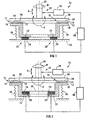
- reference numeral 10 generally refers to a seal assembly in accordance with the invention.
- the seal assembly 10 has a first seal element 1 2 defining a first sealing surface 14.
- the first seal element is an annular seal 16 which is mounted on a rigid annular carrier member 18.
- the seal assembly 10 further has a plurality of electromagnets 20, two of which are illustrated schematically in Figures 1 and 2.
- a movable component 22 of the electromagnets 20 is attached to the support 18, while a stationary component 24 of the electromagnets 20 is attached to a fixed support member 26.
- the first sealing surface 14 is shown forming a seal 15 in cooperation with a second sealing surface 28, which is defined on a rotating element 30 of a machine 32, being a power generator gas turbine, the rotating element 30 being mounted on a shaft 34.
- the seal assembly 10 further includes a biasing means, indicated schematically in the drawings by the device labelled 36.
- the biasing means 36 normally urges the annular carrier member 18 away from the support member 26, so that the first and second sealing surfaces, 14 and 28 respectively, are normally urged towards one another.
- the electromagnets 20 are operable to urge the carrier member 18 towards the support member 26 and, consequently, the first and second sealing surfaces, 14 and 28, away from one another.
- the force exerted on the annular carrier member 18 by the urging means 36 may be balanced by an opposed force exerted on the carrier member 18 by the electromagnets 20. In this way a predetermined gap may be maintained between the first and second sealing surfaces 14 and 28.
- biasing means 36 may be configured to normally urge the carrier member 18 towards the support member 26 so that the first and second sealing surfaces, 14 and 28 respectively, are normally urged away from one another.
- the electromagnets 20 are operable to urge the carrier member 18 away from the support member 26.
- the shaft 34 of a machine 32 will not run perfectly true.
- the shaft 34 may move on its bearings in an axial direction, as indicated by the arrow marked “A” in the drawings, or transversely in a radial direction, or both.
- the shaft 34 may precess about its own axis, as indicated by the arrow labelled "C” in the drawings. Consequently, the gap between the first and second sealing surfaces 14 and 28 will generally vary with each rotation of the shaft 34, if the first sealing surface 1 2 is fixed in position.
- the movement of the second sealing surface 28 is detected and measured via a sensor, indicated in the drawings by reference numeral 38, which detects displacement of the shaft 34 from a datum position, the displacement of the shaft 34 bearing a known relationship to displacement of the second sealing surface 28. It will be appreciated that displacement of the second sealing surface 28 may be detected and measured directly, as may variation in the gap between the first and second sealing surfaces 14 and 28.
- a controller indicated on the drawings by reference numeral 40, is operable to control each of the electromagnets 20 independently by varying the magnetic flux of each electromagnet 20, thereby selectively increasing or decreasing the force exerted by an electromagnet 20 on the carrier member 18.
- the entire carrier member 18, and consequently the first sealing surface 14 may be displaced axially, or tilted in any desired direction.
- the first sealing surface 14 may be controlled to mimic the movement of the second sealing surface 28 as it is displaced from its true position. Instead, the first sealing surface 14 may be controlled to maintain a preselected average gap between the first and second sealing surfaces 14 and 28.
- FIGS 3 to 5 show a seal assembly 10 in use on a gas turbine power generator rotor 50.
- FIGs 3 to 5 with reference to Figures 1 and 2, like components are indicted by like reference numerals, unless otherwise stated.
- the turbine rotor 50 has a plurality of circumferentially spaced vanes, one example of which is labelled 52, and the seal assembly 10 is located on a downstream end 54 of the rotor 50.
- the seal assembly 10 is mounted on a fixed support assembly 56 and has sixteen electromagnets 20 evenly spaced about the circumference of the support assembly 56.
- Each of the electromagnets 20 has a coil 58 and a movable core element 60, the coils 58 being mounted on the support assembly 56 and the core elements 60 being mounted on an annular carrier member 18. It will be appreciated that instead the coils 58 of the electromagnets 20 may be mounted on the carrier member 18 and the core elements 60 may be mounted on the support assembly 56.
- An annular labyrinth seal 62 is arranged on an underside 64 of the carrier member 18 and defines a labyrinthine surface 66, which comprises the first sealing surface 14 of the seal assembly 10.
- the second sealing surface 28 of the seal assembly 10 comprises an annulus defined on the downstream end 54 of the turbine rotor 50. It will be appreciated that the second sealing surface may be in any suitable form so that, for example, a second labyrinth seal may be arranged on the downstream end 54 of the turbine rotor 50 to define the second sealing surface 28.
- the second labyrinth seal may be configured to cooperate with the labyrinth seal 62 of the annular carrier member 18.
- An annular steel bellows 74 is arranged between the support assembly 56 and the carrier member 18, a first end 76 of the bellows 74 being connected to the support assembly 56 and a second end 78 of the bellows 74 being connected to the annular carrier member 18.
- the steel bellows 74 is configured to provide a biasing means 80, normally urging the labyrinth seal 62 away from the downstream end 54 of the turbine rotor 50.
- the biasing means 80 may be configured to normally urge the labyrinth seal 62 towards the second sealing surface 28.
- a stream of gas at high pressure flowing from an upstream end 68 of the turbine rotor 50 towards the downstream end 54 of the rotor 50 will create large axial forces on the turbine shaft (not shown).
- a flow of gas at high pressure is directed to a downstream region 70 adjacent the downstream end 54 of the turbine rotor 50, to reduce the difference between forces on the downstream and upstream ends, 54 and 68 respectively, of the turbine rotor 50 and balancing the axial forces operative on the turbine shaft.
- An extendably retractable gas impermeable seal 82 is provided by the bellows 74, between the downstream region 70 and a low pressure region 72, normally at atmospheric pressure.
- the first sealing surface 14 must be enabled to track the second sealing surface 28.
- At least one sensor (not shown) is provided for sensing displacement of the turbine rotor 50 from a datum position.
- a controller (not shown) is operably connected to the sensors and to the electromagnets 20 and is operable to vary the magnetic flux in the electromagnets 20 in response to a signal from the sensors on sensing a displacement of the turbine rotor 50 from its datum position. It will be appreciated that, as required, the controller may control each of the electromagnets 20 independently. Instead, the controller may control subsets of the sixteen electromagnets 20, for example groups of four adjacent electromagnets 20 to operate in unison.
Landscapes
- Engineering & Computer Science (AREA)
- General Engineering & Computer Science (AREA)
- Mechanical Engineering (AREA)
- Sealing Using Fluids, Sealing Without Contact, And Removal Of Oil (AREA)
- Turbine Rotor Nozzle Sealing (AREA)
- Mechanical Sealing (AREA)
- Gasket Seals (AREA)
- Glass Compositions (AREA)
- Materials For Medical Uses (AREA)
- Sealing Battery Cases Or Jackets (AREA)
Applications Claiming Priority (3)
| Application Number | Priority Date | Filing Date | Title |
|---|---|---|---|
| ZA9905531 | 1999-08-27 | ||
| ZA995531 | 1999-08-27 | ||
| PCT/IB2000/001152 WO2001016510A1 (en) | 1999-08-27 | 2000-08-23 | A seal assembly |
Publications (2)
| Publication Number | Publication Date |
|---|---|
| EP1206657A1 EP1206657A1 (en) | 2002-05-22 |
| EP1206657B1 true EP1206657B1 (en) | 2005-01-26 |
Family
ID=69407355
Family Applications (1)
| Application Number | Title | Priority Date | Filing Date |
|---|---|---|---|
| EP00953355A Expired - Lifetime EP1206657B1 (en) | 1999-08-27 | 2000-08-23 | A seal assembly |
Country Status (10)
| Country | Link |
|---|---|
| US (1) | US6746019B1 (ja) |
| EP (1) | EP1206657B1 (ja) |
| JP (1) | JP2003508699A (ja) |
| KR (1) | KR100663640B1 (ja) |
| CN (1) | CN100343557C (ja) |
| AT (1) | ATE288042T1 (ja) |
| AU (1) | AU6586600A (ja) |
| CA (1) | CA2382478C (ja) |
| DE (1) | DE60017756D1 (ja) |
| WO (1) | WO2001016510A1 (ja) |
Families Citing this family (22)
| Publication number | Priority date | Publication date | Assignee | Title |
|---|---|---|---|---|
| US6910857B2 (en) * | 2002-12-26 | 2005-06-28 | United Technologies Corporation | Seal |
| CN1316160C (zh) * | 2004-11-16 | 2007-05-16 | 吴雳鸣 | 双磁极双随动动静间隙处密封装置 |
| DE102006011636A1 (de) * | 2006-03-14 | 2007-09-20 | Voith Patent Gmbh | Wellendichtung |
| GB2440744B (en) * | 2006-08-09 | 2008-09-10 | Rolls Royce Plc | A blade clearance arrangement |
| US7748945B2 (en) * | 2006-12-07 | 2010-07-06 | Jerry Wayne Johnson | Floating sealing ring |
| US8133003B2 (en) * | 2008-09-26 | 2012-03-13 | General Electric Company | Magnetic adjustment of turbomachinery components |
| US8740563B2 (en) | 2010-11-22 | 2014-06-03 | General Electric Company | Sealing assembly for use in turbomachines and methods of assembling same |
| US9360118B2 (en) * | 2011-02-03 | 2016-06-07 | Eagle Industry Co., Ltd. | Magnetic fluid seal |
| US9255642B2 (en) * | 2012-07-06 | 2016-02-09 | General Electric Company | Aerodynamic seals for rotary machine |
| US9322478B2 (en) * | 2012-07-31 | 2016-04-26 | General Electric Company | Seal system and method for rotary machine |
| CN103423456A (zh) * | 2013-08-27 | 2013-12-04 | 刘讯岐 | 一种紧顶定位磁力机械密封件 |
| EP2995772A1 (en) * | 2014-09-15 | 2016-03-16 | Alstom Technology Ltd | Mounting and sealing arrangement for a guide vane of a gas turbine |
| WO2017027382A1 (en) * | 2015-08-10 | 2017-02-16 | Exxonmobil Upstream Research Company | Device and method for magnetically controlled dry gas seal |
| DE102016108463A1 (de) * | 2016-05-09 | 2017-11-09 | Man Diesel & Turbo Se | Labyrinthdichtung |
| US10436328B2 (en) | 2016-06-10 | 2019-10-08 | John Crane Uk Ltd. | Dry gas seal with electronically controlled shutdown valve |
| US10132412B2 (en) * | 2016-08-05 | 2018-11-20 | Exxonmobil Upstream Research Company | Device and method for controlling rotating equipment seal without buffer support equipment |
| EP3339581A1 (en) * | 2016-12-22 | 2018-06-27 | Ansaldo Energia S.p.A. | Sealing system for a rotating machine |
| EP3604870A4 (en) | 2017-03-30 | 2020-12-23 | Eagle Industry Co., Ltd. | SEALING DEVICE |
| AU2018270137B2 (en) | 2017-05-15 | 2024-03-28 | John Crane Uk Ltd. | Dry gas seal with electronically controlled carrier load |
| US10465544B2 (en) * | 2017-07-24 | 2019-11-05 | United Technologies Corporation | Eddy current damper for lift off seal |
| CN107355536B (zh) * | 2017-08-31 | 2018-09-25 | 安徽江淮汽车集团股份有限公司 | 一种封堵限位装置 |
| JP7033876B2 (ja) * | 2017-09-29 | 2022-03-11 | 極東開発工業株式会社 | 天蓋開閉装置付コンテナ |
Family Cites Families (8)
| Publication number | Priority date | Publication date | Assignee | Title |
|---|---|---|---|---|
| US3971563A (en) * | 1973-09-17 | 1976-07-27 | Mitsui Shipbuilding And Engineering Co., Ltd. | Shaft sealing apparatus using a fluid sealing system |
| DE3221380C1 (de) * | 1982-06-05 | 1983-07-28 | M.A.N. Maschinenfabrik Augsburg-Nürnberg AG, 4200 Oberhausen | Wellendichtung mit aktiv-magnetisch geregeltem Dichtspalt |
| DE3505048A1 (de) * | 1985-02-14 | 1986-08-14 | MTU Motoren- und Turbinen-Union München GmbH, 8000 München | Hydro- oder gasdynamisches gleitlager fuer hohe drehzahlen |
| JPH0314372U (ja) * | 1989-06-28 | 1991-02-13 | ||
| US5064205A (en) * | 1990-05-23 | 1991-11-12 | General Electric Company | Active magnetic seal |
| US5137286A (en) * | 1991-08-23 | 1992-08-11 | General Electric Company | Permanent magnet floating shaft seal |
| US5263816A (en) * | 1991-09-03 | 1993-11-23 | General Motors Corporation | Turbomachine with active tip clearance control |
| GB2336408B (en) * | 1998-04-17 | 2002-07-24 | Rolls Royce Plc | A seal arrangement |
-
2000
- 2000-08-23 EP EP00953355A patent/EP1206657B1/en not_active Expired - Lifetime
- 2000-08-23 KR KR1020027002475A patent/KR100663640B1/ko active IP Right Grant
- 2000-08-23 CA CA002382478A patent/CA2382478C/en not_active Expired - Lifetime
- 2000-08-23 DE DE60017756T patent/DE60017756D1/de not_active Expired - Lifetime
- 2000-08-23 AT AT00953355T patent/ATE288042T1/de not_active IP Right Cessation
- 2000-08-23 WO PCT/IB2000/001152 patent/WO2001016510A1/en active IP Right Grant
- 2000-08-23 AU AU65866/00A patent/AU6586600A/en not_active Abandoned
- 2000-08-23 JP JP2001520030A patent/JP2003508699A/ja active Pending
- 2000-08-23 US US10/070,022 patent/US6746019B1/en not_active Expired - Lifetime
- 2000-08-23 CN CNB008120005A patent/CN100343557C/zh not_active Expired - Lifetime
Also Published As
| Publication number | Publication date |
|---|---|
| ATE288042T1 (de) | 2005-02-15 |
| CN1371456A (zh) | 2002-09-25 |
| US6746019B1 (en) | 2004-06-08 |
| KR100663640B1 (ko) | 2007-01-03 |
| CN100343557C (zh) | 2007-10-17 |
| WO2001016510A1 (en) | 2001-03-08 |
| EP1206657A1 (en) | 2002-05-22 |
| JP2003508699A (ja) | 2003-03-04 |
| DE60017756D1 (de) | 2005-03-03 |
| CA2382478A1 (en) | 2001-03-08 |
| CA2382478C (en) | 2008-11-04 |
| AU6586600A (en) | 2001-03-26 |
| KR20020036847A (ko) | 2002-05-16 |
Similar Documents
| Publication | Publication Date | Title |
|---|---|---|
| EP1206657B1 (en) | A seal assembly | |
| EP0580201B1 (en) | Magnetic bearing back-up | |
| EP0580202B1 (en) | Magnetic bearing back-up | |
| US5137286A (en) | Permanent magnet floating shaft seal | |
| EP0578285B1 (en) | Turbomachine with active tip-clearance control | |
| US5791868A (en) | Thrust load compensating system for a compliant foil hydrodynamic fluid film thrust bearing | |
| US5064205A (en) | Active magnetic seal | |
| US5836739A (en) | Gas turbine engine | |
| US7344357B2 (en) | Methods and apparatus for assembling a rotary machine | |
| US4447063A (en) | Shaft seal with positively magnetically controlled sealing gap | |
| US9995339B2 (en) | Turbo machine with magnetic bearings | |
| JPH02500926A (ja) | 静水圧スラスト軸受装置 | |
| EP0834020A1 (en) | Shaft bearing system | |
| EP0950798A3 (en) | Temperature responsive packing ring with uniform clearance | |
| CA2087690A1 (en) | Tip clearance control apparatus for a turbo-machine blade | |
| CN101260941A (zh) | 用于旋转机械的机械密封系统和方法 | |
| US20030077187A1 (en) | Molecular pump for forming a vacuum | |
| GB2298901A (en) | Gas turbine engine axial thrust balancing | |
| JPS58221074A (ja) | 軸封装置 | |
| US6881918B2 (en) | Electric discharge machining apparatus | |
| EP2425099B1 (en) | Turbine for the expansion of gas/vapour provided with axial thrust compensation on the drive shaft | |
| JPH05253836A (ja) | 主軸の自動バランス装置 | |
| EP1072805A2 (en) | Magnetic bearing device | |
| JPH09257034A (ja) | 磁気軸受と静圧軸受を備えた流体機械 | |
| JP2510398Y2 (ja) | ラビリンスシ―ル装置 |
Legal Events
| Date | Code | Title | Description |
|---|---|---|---|
| PUAI | Public reference made under article 153(3) epc to a published international application that has entered the european phase |
Free format text: ORIGINAL CODE: 0009012 |
|
| 17P | Request for examination filed |
Effective date: 20020222 |
|
| AX | Request for extension of the european patent |
Free format text: AL;LT;LV;MK;RO;SI |
|
| 17Q | First examination report despatched |
Effective date: 20031111 |
|
| GRAP | Despatch of communication of intention to grant a patent |
Free format text: ORIGINAL CODE: EPIDOSNIGR1 |
|
| GRAS | Grant fee paid |
Free format text: ORIGINAL CODE: EPIDOSNIGR3 |
|
| GRAA | (expected) grant |
Free format text: ORIGINAL CODE: 0009210 |
|
| AK | Designated contracting states |
Kind code of ref document: B1 Designated state(s): AT BE CH CY DE DK ES FI FR GB GR IE IT LI LU MC NL PT SE |
|
| PG25 | Lapsed in a contracting state [announced via postgrant information from national office to epo] |
Ref country code: IT Free format text: LAPSE BECAUSE OF FAILURE TO SUBMIT A TRANSLATION OF THE DESCRIPTION OR TO PAY THE FEE WITHIN THE PRESCRIBED TIME-LIMIT;WARNING: LAPSES OF ITALIAN PATENTS WITH EFFECTIVE DATE BEFORE 2007 MAY HAVE OCCURRED AT ANY TIME BEFORE 2007. THE CORRECT EFFECTIVE DATE MAY BE DIFFERENT FROM THE ONE RECORDED. Effective date: 20050126 Ref country code: NL Free format text: LAPSE BECAUSE OF FAILURE TO SUBMIT A TRANSLATION OF THE DESCRIPTION OR TO PAY THE FEE WITHIN THE PRESCRIBED TIME-LIMIT Effective date: 20050126 Ref country code: FI Free format text: LAPSE BECAUSE OF FAILURE TO SUBMIT A TRANSLATION OF THE DESCRIPTION OR TO PAY THE FEE WITHIN THE PRESCRIBED TIME-LIMIT Effective date: 20050126 Ref country code: BE Free format text: LAPSE BECAUSE OF FAILURE TO SUBMIT A TRANSLATION OF THE DESCRIPTION OR TO PAY THE FEE WITHIN THE PRESCRIBED TIME-LIMIT Effective date: 20050126 Ref country code: AT Free format text: LAPSE BECAUSE OF FAILURE TO SUBMIT A TRANSLATION OF THE DESCRIPTION OR TO PAY THE FEE WITHIN THE PRESCRIBED TIME-LIMIT Effective date: 20050126 |
|
| REG | Reference to a national code |
Ref country code: GB Ref legal event code: FG4D Ref country code: IE Ref legal event code: FG4D |
|
| REG | Reference to a national code |
Ref country code: CH Ref legal event code: EP |
|
| REF | Corresponds to: |
Ref document number: 60017756 Country of ref document: DE Date of ref document: 20050303 Kind code of ref document: P |
|
| PG25 | Lapsed in a contracting state [announced via postgrant information from national office to epo] |
Ref country code: GR Free format text: LAPSE BECAUSE OF FAILURE TO SUBMIT A TRANSLATION OF THE DESCRIPTION OR TO PAY THE FEE WITHIN THE PRESCRIBED TIME-LIMIT Effective date: 20050426 Ref country code: SE Free format text: LAPSE BECAUSE OF FAILURE TO SUBMIT A TRANSLATION OF THE DESCRIPTION OR TO PAY THE FEE WITHIN THE PRESCRIBED TIME-LIMIT Effective date: 20050426 Ref country code: DK Free format text: LAPSE BECAUSE OF FAILURE TO SUBMIT A TRANSLATION OF THE DESCRIPTION OR TO PAY THE FEE WITHIN THE PRESCRIBED TIME-LIMIT Effective date: 20050426 |
|
| PG25 | Lapsed in a contracting state [announced via postgrant information from national office to epo] |
Ref country code: DE Free format text: LAPSE BECAUSE OF FAILURE TO SUBMIT A TRANSLATION OF THE DESCRIPTION OR TO PAY THE FEE WITHIN THE PRESCRIBED TIME-LIMIT Effective date: 20050427 |
|
| PG25 | Lapsed in a contracting state [announced via postgrant information from national office to epo] |
Ref country code: ES Free format text: LAPSE BECAUSE OF FAILURE TO SUBMIT A TRANSLATION OF THE DESCRIPTION OR TO PAY THE FEE WITHIN THE PRESCRIBED TIME-LIMIT Effective date: 20050507 |
|
| NLV1 | Nl: lapsed or annulled due to failure to fulfill the requirements of art. 29p and 29m of the patents act | ||
| PG25 | Lapsed in a contracting state [announced via postgrant information from national office to epo] |
Ref country code: CY Free format text: LAPSE BECAUSE OF FAILURE TO SUBMIT A TRANSLATION OF THE DESCRIPTION OR TO PAY THE FEE WITHIN THE PRESCRIBED TIME-LIMIT Effective date: 20050823 Ref country code: IE Free format text: LAPSE BECAUSE OF NON-PAYMENT OF DUE FEES Effective date: 20050823 Ref country code: LU Free format text: LAPSE BECAUSE OF NON-PAYMENT OF DUE FEES Effective date: 20050823 |
|
| PG25 | Lapsed in a contracting state [announced via postgrant information from national office to epo] |
Ref country code: MC Free format text: LAPSE BECAUSE OF NON-PAYMENT OF DUE FEES Effective date: 20050831 |
|
| REG | Reference to a national code |
Ref country code: CH Ref legal event code: NV Representative=s name: OK PAT AG PATENTE MARKEN LIZENZEN Ref country code: CH Ref legal event code: PUE Owner name: PEBBLE BED MODULAR REACTOR PROPRIETARY LIMITED Free format text: ESKOM#MEGAWATT PARK, MAXWELL DRIVE, SUNNINGHILL, SANDTON#2157 GAUTENG (ZA) -TRANSFER TO- PEBBLE BED MODULAR REACTOR PROPRIETARY LIMITED#3 RD FLOOR,LAKE BUENA VISTA BUILDING 1267 GORDON HOOD AVENUE CENTURION CENTRE#CENTURION 0046 (ZA) |
|
| REG | Reference to a national code |
Ref country code: GB Ref legal event code: 732E |
|
| PLBE | No opposition filed within time limit |
Free format text: ORIGINAL CODE: 0009261 |
|
| STAA | Information on the status of an ep patent application or granted ep patent |
Free format text: STATUS: NO OPPOSITION FILED WITHIN TIME LIMIT |
|
| 26N | No opposition filed |
Effective date: 20051027 |
|
| REG | Reference to a national code |
Ref country code: FR Ref legal event code: TP |
|
| ET | Fr: translation filed | ||
| REG | Reference to a national code |
Ref country code: IE Ref legal event code: MM4A |
|
| PG25 | Lapsed in a contracting state [announced via postgrant information from national office to epo] |
Ref country code: PT Free format text: LAPSE BECAUSE OF NON-PAYMENT OF DUE FEES Effective date: 20050626 |
|
| REG | Reference to a national code |
Ref country code: FR Ref legal event code: PLFP Year of fee payment: 16 |
|
| REG | Reference to a national code |
Ref country code: FR Ref legal event code: PLFP Year of fee payment: 17 |
|
| REG | Reference to a national code |
Ref country code: FR Ref legal event code: PLFP Year of fee payment: 18 |
|
| REG | Reference to a national code |
Ref country code: FR Ref legal event code: PLFP Year of fee payment: 19 |
|
| PGFP | Annual fee paid to national office [announced via postgrant information from national office to epo] |
Ref country code: FR Payment date: 20190730 Year of fee payment: 20 |
|
| PGFP | Annual fee paid to national office [announced via postgrant information from national office to epo] |
Ref country code: GB Payment date: 20190822 Year of fee payment: 20 |
|
| PGFP | Annual fee paid to national office [announced via postgrant information from national office to epo] |
Ref country code: CH Payment date: 20190819 Year of fee payment: 20 |
|
| REG | Reference to a national code |
Ref country code: CH Ref legal event code: PL |
|
| REG | Reference to a national code |
Ref country code: GB Ref legal event code: PE20 Expiry date: 20200822 |
|
| PG25 | Lapsed in a contracting state [announced via postgrant information from national office to epo] |
Ref country code: GB Free format text: LAPSE BECAUSE OF EXPIRATION OF PROTECTION Effective date: 20200822 |