EP1206643B1 - Vorrichtung zum fördern von polymerdispersionen - Google Patents
Vorrichtung zum fördern von polymerdispersionen Download PDFInfo
- Publication number
- EP1206643B1 EP1206643B1 EP00958503A EP00958503A EP1206643B1 EP 1206643 B1 EP1206643 B1 EP 1206643B1 EP 00958503 A EP00958503 A EP 00958503A EP 00958503 A EP00958503 A EP 00958503A EP 1206643 B1 EP1206643 B1 EP 1206643B1
- Authority
- EP
- European Patent Office
- Prior art keywords
- impeller
- hub
- transporting
- wing
- transporting according
- Prior art date
- Legal status (The legal status is an assumption and is not a legal conclusion. Google has not performed a legal analysis and makes no representation as to the accuracy of the status listed.)
- Expired - Lifetime
Links
Images

Classifications
-
- F—MECHANICAL ENGINEERING; LIGHTING; HEATING; WEAPONS; BLASTING
- F04—POSITIVE - DISPLACEMENT MACHINES FOR LIQUIDS; PUMPS FOR LIQUIDS OR ELASTIC FLUIDS
- F04D—NON-POSITIVE-DISPLACEMENT PUMPS
- F04D29/00—Details, component parts, or accessories
- F04D29/18—Rotors
- F04D29/22—Rotors specially for centrifugal pumps
- F04D29/2205—Conventional flow pattern
- F04D29/2222—Construction and assembly
- F04D29/2233—Construction and assembly entirely open or stamped from one sheet
Definitions
- the invention relates to a device for conveying Polymer dispersions, such as in a stirred tank reactor to produce shear-sensitive polymer dispersions.
- the polymer dispersions to be produced can be very sensitive to shear and change their viscosity over a wide range during the manufacturing process.
- the Polymer dispersions can tend to form coagulate and a foam-like Adopt product consistency, creating special requirements for that Pump to circulate the reaction mixture.
- the pump should Promote as little shear as possible so that coagulum formation does not occur the pump must be insensitive to gas components in the product to be pumped. Further the pump should be insensitive to a certain amount of deposits.
- a device comprising an impeller, suitable for conveying media, in particular for conveying polymer dispersions is known from US-A-3,322,070.
- the object of the invention based on the adherence of polymer dispersions to these promoting Avoid devices as far as possible.
- a Drive is drivable and the wheels of the device from a housing can be surrounded in the area of the hub of the wheels a number of ten curved Wings is freely taken up, the pressure and suction side of the same geometry, such that the pumping spaces on the front and flow through the back of the impeller evenly.
- the angle of entry for the medium into the pumping chambers or the wing panniers of the impeller between 30 ° and 120 °, preferably 90 ° at the inlet hub.
- This ensures a uniform inflow of the medium, such as one shear-sensitive polymer dispersion, guaranteed.
- the hub of the Impeller can accommodate between six and twelve individual blades, where the number of blades from the total diameter of the impeller, the Viscosity of the shear-sensitive products to be conveyed and the Speed of the drive is dependent.
- the circumference of the hub eight wings added are on the circumference of the hub eight wings added.
- the entire impeller can preferably be coated with a conductive PFA be provided.
- the wings that delimit the pumping spaces of the impeller point to theirs Front, the pressure side and on their back, the suction side, the same Curvature course on. So the front and back can be the same Have radius of curvature, the edges of all wings well rounded are designed to the flow movement of the shear sensitive Polymer dispersions around the individual wings and in the area of the Shaft hub not to hinder.
- the curvature of the center lines of the single wing between the center of the hub and the outer envelope Circle segment describe what an easier manufacture of the wing geometry allows.
- the cross sectional area of each with the hub of the impeller connected wing is dimensioned so that the pump room delimiting Areas on the pressure and suction side of the wings are wider than that Material thickness of the wings.
- the material thickness may be one not fall below a certain value, the design of the impeller in With regard to the mechanical strength, the speed must also be taken into account and the media to be conveyed with the impeller according to the invention.
- an impeller according to the invention is centered in a surrounding one Spiral housing arranged, so the desired can be advantageous Realize delivery rates even at relatively low drive speeds, whereby the material stress occurring compared to at higher speeds Occurring stresses are relatively low, which is the life of the Impeller significantly increased.
- the impeller according to the invention allows coagulation to be more sensitive to shear Conveying from a stirred tank reactor avoiding polymer dispersions a heat exchanger to extract the exothermic heat of reaction and can can be provided particularly advantageously in the associated circulation system.
- the impeller itself can protrude freely into the pump chamber as well as from be enclosed in a housing, depending on the intended application.
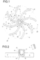
- the impeller 28 is on its shaft hub 1 on a drive shaft Drive attached and has a number of wings 2, all of which on the Hub 1 are attached.
- the individual wings 2 are of a larger size Wing width 4 compared to their material thickness 3 and have an im essential rectangular cross-sectional profile. Between each Wings 2 are pumping spaces 5, each of a wing front 7 and one wing back 8 are limited.
- the wing front 7 represents the Pressure side, the wing back 8, however, the suction side of the running channel on Vane wheel 28.
- the individual vanes 2 are in a vane curvature 9 formed, starting from the respective wing root 10 along the Center line 11 of wing 2 extends to envelope 6, which is the ends of all Wing 2 of the impeller 28 encloses.
- wing 2 Relative to the tangents to the center lines 11 in the area of Flights / roots 10 of wing 2 are the individual wings 2 around Pitch angle 12 arranged to each other.
- the between two wing roots 10 trained free spaces 14 are offset from each other by the pitch angle 13 arranged, where - with eight blades 2 on the impeller 28 - both the Pitch angle 12 for the wing 2 45 ° and the pitch angle 13 for the Free spaces 14 45 °.
- the wings 2 can for example between the Envelope 6 and the center of the hub 1 with its center line 11 Describe a segment of a circle, as indicated in FIG. 1. This wing geometry can be manufactured inexpensively in terms of production technology.
- the wings 2 each have a front 7 and a back 8, the Front 7 and back 8 have identical curvatures.
- the free arrangement of the wings 2 around the hub 1 no dead spaces occur in the Pumping up, so that a relative movement between the polymer dispersion and the impeller 28 is guaranteed at all times. Because anytime and anywhere during the flow through the pumping spaces 5 relative movements between Medium and contact surfaces on the impeller 28 only occur minimal deposits of polymerized material on the impeller 28 and on it training surrounding housing.
- the direction of rotation 20 of the impeller 28 forms the front 7 Wing 2 the respective pressure side of the running channel, while on the back 8 the wing 2 forms the suction side, in which new medium to be pumped nachströmt.
- the wings 2 are each well rounded in the area of their edges executed so that there is a low-shear flow around the individual Set wing 2 on the impeller 28. Length and curvature of the individual Vane 2 determine the diameter 29 of the impeller 28, the length of the Wing 2 is dimensioned so that they also close to the envelope 6 End areas have sufficient strength properties.
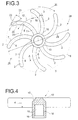
- Figure 2 shows the section through an impeller 28, the section through the Shaft hub 1 is placed. There is a thread 16 at a blind hole 15 intended. The thread 16 is such that the direction of rotation of the Thread 16 is directed against the direction of rotation of the impeller 28, the Impeller 28 during its rotation in the direction of rotation 20 during operation is unable to solve, but constantly follows.
- the view Figure 2 also shows the wing root 10 on which the wing 2 with the Hub 1 are connected to which on the drive side of the hub 1 Hub extension 17 extends. In the area of the wing root 10 there are bevels of about 45 ° to avoid that in the case of shear sensitive Materials there deposits on the wing root 10 of the impeller 28 occur.
- FIG. 3 shows an impeller 28, which has a smaller diameter 29 is executed, nevertheless takes up eight wings 2 on the hub 1, but which in Compared to the configuration according to Figure 1 are more curved.
- the ends of the wings 2 lie within the envelope 6, their respective Center line 11 is designed with a radius of curvature 21 which is smaller than that 1 is the radius of curvature shown in FIG.
- the front 7, the print side, as well as the back 8, the suction side have an identical curvature executed and form the respective pumping spaces 5 between them.
- To the Ends of the wings 2 lies between the tangent 22 to the envelope 6 and the Tangent 24 to the center line 11 of the wing 2 of the exit angle 23, under which the shear-sensitive polymer dispersion from the respective pump chamber 5 exit.
- the pitch angle 12 at which the wing 2 on the circumference of the hub 1st are arranged, is also 45 ° in the embodiment shown in Figure 3.
- the angular offset 18 is between the intersecting the envelope 6 Vertical from the end of the wing 2 through the center of the hub 1 and Back 8 of the wing 2 extending distance marked.
- the material thickness 3 of the Wing 2 is also smaller than that in the configuration shown in Figure 3 Blade width 4 of the blades, which increases the pump efficiency.
- Figure 4 shows a section through the shaft hub 1 of the impeller 28 according to FIG. 3.
- the edges of the wings 2, which are well rounded as in FIG. 1 allow a flow around the wing 2 through the medium to be conveyed without that it builds up in the contact area by forming dead spaces and Layer structure of polymerized material comes.
- Hub extension 17 executed a blind hole 15 in which a thread 16 is provided is. Analogous to the configuration already described above, this is done here Connection between the drive shaft of the drive motor or gearbox and the Impeller 28.
- FIG. 5 shows the top view of the impeller 28 according to FIG. 3, which is shown in FIG Direction of rotation 20 rotates.
- the pumping spaces 5 or wing bags 25 are curved by the Front sides 7, the printed pages and the curved rear sides 8, limited the suction sides of the wing 2.
- the wings 2 are provided with bevels at an angle of about 45 ° to flow around the To achieve hub area of the impeller 28.
- the free spaces 14 are provided between the wing roots 10 of the individual wings 2 Radii of curvature 27 are formed which are centered on the width 26 of the free space 14 lie. Due to the adjacent free spaces 14 arises in Hub area is a star-shaped flow area that flows through the shear-sensitive polymer dispersion allows without it to build up coagulated polymer material comes.
- the impeller 28 can be made of metal, with a deburring of the Special attention must be paid to the contact areas of the individual wings 2.
- the individual wings 2 in the area of the hub 1 also on their outer circumference, for example by means of a thermal joining process be fixed before coating the outer surfaces with a conductive material, such as PFA.
Landscapes
- Engineering & Computer Science (AREA)
- Mechanical Engineering (AREA)
- General Engineering & Computer Science (AREA)
- Structures Of Non-Positive Displacement Pumps (AREA)
- Polymerisation Methods In General (AREA)
- Other Resins Obtained By Reactions Not Involving Carbon-To-Carbon Unsaturated Bonds (AREA)
Applications Claiming Priority (3)
| Application Number | Priority Date | Filing Date | Title |
|---|---|---|---|
| DE19940399 | 1999-08-25 | ||
| DE19940399A DE19940399A1 (de) | 1999-08-25 | 1999-08-25 | Vorrichtung zum Fördern von Polymerdispersionen |
| PCT/EP2000/008349 WO2001014749A1 (de) | 1999-08-25 | 2000-08-25 | Vorrichtung zum fördern von polymerdispersionen |
Publications (2)
| Publication Number | Publication Date |
|---|---|
| EP1206643A1 EP1206643A1 (de) | 2002-05-22 |
| EP1206643B1 true EP1206643B1 (de) | 2004-02-25 |
Family
ID=7919620
Family Applications (1)
| Application Number | Title | Priority Date | Filing Date |
|---|---|---|---|
| EP00958503A Expired - Lifetime EP1206643B1 (de) | 1999-08-25 | 2000-08-25 | Vorrichtung zum fördern von polymerdispersionen |
Country Status (8)
| Country | Link |
|---|---|
| US (1) | US20050276159A1 (es) |
| EP (1) | EP1206643B1 (es) |
| AR (1) | AR053641A1 (es) |
| AU (1) | AU6999800A (es) |
| BR (1) | BR0013477B1 (es) |
| DE (2) | DE19940399A1 (es) |
| MX (1) | MXPA02001578A (es) |
| WO (1) | WO2001014749A1 (es) |
Families Citing this family (2)
| Publication number | Priority date | Publication date | Assignee | Title |
|---|---|---|---|---|
| DE102007040850A1 (de) | 2007-08-29 | 2009-03-05 | Wacker Chemie Ag | Verfahren zur Herstellung von Schutzkolloid-stabilisierten Polymerisaten und Vorrichtung zur Durchführung des Verfahrens |
| DE102011087138A1 (de) | 2011-11-25 | 2013-05-29 | Wacker Chemie Ag | Verfahren zur Herstellung von wässrigen Polymerdispersionen |
Family Cites Families (16)
| Publication number | Priority date | Publication date | Assignee | Title |
|---|---|---|---|---|
| US1646913A (en) * | 1923-11-19 | 1927-10-25 | Jost Fred | Apparatus for mixing fluids of different densities |
| US1822867A (en) * | 1930-01-21 | 1931-09-08 | Carlos Horacio Amaro Salgu San | Propeller |
| US2117011A (en) * | 1935-02-27 | 1938-05-10 | Ward E Pratt | Centrifugal pump |
| US2436767A (en) * | 1941-12-31 | 1948-02-24 | Jasco Inc | Low-temperature polymer production |
| US2671408A (en) * | 1947-03-10 | 1954-03-09 | Itt | Pump |
| US2854320A (en) * | 1955-12-15 | 1958-09-30 | Du Pont | Polymerization reaction vessel |
| US3390004A (en) * | 1965-09-01 | 1968-06-25 | American Cyanamid Co | Manufacture of paste rosin size in closed circuit reactor |
| NL6600964A (es) * | 1966-01-26 | 1967-07-27 | ||
| US3322070A (en) * | 1966-03-11 | 1967-05-30 | Allis Chalmers Mfg Co | Vortex pump |
| DE1694348C3 (de) * | 1967-11-21 | 1975-09-25 | Enka Glanzstoff Ag, 5600 Wuppertal | Verfahren zum kontinuierlichen Einmischen einer Pigmentdispersion in eine Polyamidschmelze |
| UST864006I4 (en) * | 1968-11-20 | 1969-07-15 | Spangler etal def. pub. polymerization reactor for spandex polymers | |
| DE1910482B2 (de) * | 1969-03-01 | 1972-11-16 | Chemische Werke Hüls AG, 4370 Mari | Polymerisationsreaktor |
| DE2038363B2 (de) * | 1970-08-01 | 1974-10-03 | Chemische Werke Huels Ag, 4370 Marl | Verfahren und Vorrichtung zum Kühlen von Polymerisationsansätzen |
| US3704868A (en) * | 1970-09-25 | 1972-12-05 | Ecodyne Corp | Mechanical aerator |
| US4722664A (en) * | 1981-06-05 | 1988-02-02 | The Duriron Company, Inc. | Lined corrosion resistant pump |
| US5276113A (en) * | 1989-05-22 | 1994-01-04 | Kanegafuchi Chemical Industry Co., Ltd. | Process for suspension polymerization |
-
1999
- 1999-08-25 DE DE19940399A patent/DE19940399A1/de not_active Withdrawn
-
2000
- 2000-08-24 AR ARP000104385A patent/AR053641A1/es unknown
- 2000-08-25 MX MXPA02001578A patent/MXPA02001578A/es active IP Right Grant
- 2000-08-25 BR BRPI0013477-5A patent/BR0013477B1/pt not_active IP Right Cessation
- 2000-08-25 AU AU69998/00A patent/AU6999800A/en not_active Abandoned
- 2000-08-25 DE DE50005445T patent/DE50005445D1/de not_active Expired - Lifetime
- 2000-08-25 WO PCT/EP2000/008349 patent/WO2001014749A1/de active IP Right Grant
- 2000-08-25 EP EP00958503A patent/EP1206643B1/de not_active Expired - Lifetime
-
2005
- 2005-08-17 US US11/205,068 patent/US20050276159A1/en not_active Abandoned
Also Published As
| Publication number | Publication date |
|---|---|
| WO2001014749A1 (de) | 2001-03-01 |
| AR053641A1 (es) | 2007-05-16 |
| US20050276159A1 (en) | 2005-12-15 |
| AU6999800A (en) | 2001-03-19 |
| EP1206643A1 (de) | 2002-05-22 |
| DE19940399A1 (de) | 2001-03-01 |
| MXPA02001578A (es) | 2002-07-02 |
| DE50005445D1 (de) | 2004-04-01 |
| BR0013477A (pt) | 2002-04-30 |
| BR0013477B1 (pt) | 2009-01-13 |
Similar Documents
| Publication | Publication Date | Title |
|---|---|---|
| DE69314912T2 (de) | Seitenkanalpumpe und Verfahren zur Herstellung des Laufrades | |
| DE69914134T2 (de) | Laufrad | |
| DE69924558T2 (de) | Vakuumpumpe | |
| DE69211607T2 (de) | Laufrad für Wasserpumpe | |
| EP1797327B1 (de) | Drehkolbenpumpe mit einem pumpengehäuse und zwei zweiflügeligen drehkolben | |
| DE69111664T2 (de) | Blutpumpe und Apparat für die extracorporale Blutzirkulation. | |
| WO2007085231A1 (de) | Laufrad | |
| DE60009593T2 (de) | Glasbeschichtetes Axialströmungslaufrad | |
| EP2646693B1 (de) | Kühlmittelpumpe | |
| EP1937980B1 (de) | Rotor für eine strömungsmaschine und eine strömungsmaschine | |
| DE112014002022T5 (de) | Luftgebläse für ein Brennstoffzellenfahrzeug | |
| EP1206643B1 (de) | Vorrichtung zum fördern von polymerdispersionen | |
| EP0874161A1 (de) | Kreiselpumpe | |
| WO2017129794A1 (de) | Kolben für eine drehkolbenpumpe | |
| EP0363503A1 (de) | Pumpenstufe für eine Hochvakuumpumpe | |
| EP2497956A1 (de) | Freistrompumpe | |
| EP3994359A2 (de) | Pumpenanordnung | |
| EP1886026B1 (de) | Wasserpumpe | |
| EP1606516B1 (de) | Kraftstoffpumpe | |
| DE2163011A1 (de) | Seitenkanalverdichter | |
| EP1021655B1 (de) | Förderpumpe | |
| DE19912314C2 (de) | Förderpumpe | |
| DE4037205A1 (de) | Pumpenrad | |
| DE3502839A1 (de) | Pumpe | |
| EP2480321B1 (de) | Axialwirkendes rührorgan |
Legal Events
| Date | Code | Title | Description |
|---|---|---|---|
| PUAI | Public reference made under article 153(3) epc to a published international application that has entered the european phase |
Free format text: ORIGINAL CODE: 0009012 |
|
| 17P | Request for examination filed |
Effective date: 20020118 |
|
| AX | Request for extension of the european patent |
Free format text: AL;LT;LV;MK;RO;SI |
|
| GRAP | Despatch of communication of intention to grant a patent |
Free format text: ORIGINAL CODE: EPIDOSNIGR1 |
|
| GRAS | Grant fee paid |
Free format text: ORIGINAL CODE: EPIDOSNIGR3 |
|
| GRAA | (expected) grant |
Free format text: ORIGINAL CODE: 0009210 |
|
| AK | Designated contracting states |
Kind code of ref document: B1 Designated state(s): DE FI FR NL |
|
| REG | Reference to a national code |
Ref country code: IE Ref legal event code: FG4D Free format text: GERMAN |
|
| REF | Corresponds to: |
Ref document number: 50005445 Country of ref document: DE Date of ref document: 20040401 Kind code of ref document: P |
|
| LTIE | Lt: invalidation of european patent or patent extension |
Effective date: 20040225 |
|
| REG | Reference to a national code |
Ref country code: IE Ref legal event code: FD4D |
|
| ET | Fr: translation filed | ||
| PLBE | No opposition filed within time limit |
Free format text: ORIGINAL CODE: 0009261 |
|
| STAA | Information on the status of an ep patent application or granted ep patent |
Free format text: STATUS: NO OPPOSITION FILED WITHIN TIME LIMIT |
|
| 26N | No opposition filed |
Effective date: 20041126 |
|
| PGFP | Annual fee paid to national office [announced via postgrant information from national office to epo] |
Ref country code: NL Payment date: 20080803 Year of fee payment: 9 |
|
| PGFP | Annual fee paid to national office [announced via postgrant information from national office to epo] |
Ref country code: FI Payment date: 20090813 Year of fee payment: 10 |
|
| REG | Reference to a national code |
Ref country code: NL Ref legal event code: V1 Effective date: 20100301 |
|
| PG25 | Lapsed in a contracting state [announced via postgrant information from national office to epo] |
Ref country code: NL Free format text: LAPSE BECAUSE OF NON-PAYMENT OF DUE FEES Effective date: 20100301 |
|
| PG25 | Lapsed in a contracting state [announced via postgrant information from national office to epo] |
Ref country code: FI Free format text: LAPSE BECAUSE OF NON-PAYMENT OF DUE FEES Effective date: 20100825 |
|
| REG | Reference to a national code |
Ref country code: FR Ref legal event code: PLFP Year of fee payment: 16 |
|
| REG | Reference to a national code |
Ref country code: FR Ref legal event code: PLFP Year of fee payment: 17 |
|
| PGFP | Annual fee paid to national office [announced via postgrant information from national office to epo] |
Ref country code: FR Payment date: 20160829 Year of fee payment: 17 |
|
| PGFP | Annual fee paid to national office [announced via postgrant information from national office to epo] |
Ref country code: DE Payment date: 20161031 Year of fee payment: 17 |
|
| REG | Reference to a national code |
Ref country code: DE Ref legal event code: R119 Ref document number: 50005445 Country of ref document: DE |
|
| REG | Reference to a national code |
Ref country code: FR Ref legal event code: ST Effective date: 20180430 |
|
| PG25 | Lapsed in a contracting state [announced via postgrant information from national office to epo] |
Ref country code: DE Free format text: LAPSE BECAUSE OF NON-PAYMENT OF DUE FEES Effective date: 20180301 |
|
| PG25 | Lapsed in a contracting state [announced via postgrant information from national office to epo] |
Ref country code: FR Free format text: LAPSE BECAUSE OF NON-PAYMENT OF DUE FEES Effective date: 20170831 |