EP1206136A2 - Vorrichtung und Verfahren zur Videodatenaufzeichnung - Google Patents
Vorrichtung und Verfahren zur Videodatenaufzeichnung Download PDFInfo
- Publication number
- EP1206136A2 EP1206136A2 EP01126441A EP01126441A EP1206136A2 EP 1206136 A2 EP1206136 A2 EP 1206136A2 EP 01126441 A EP01126441 A EP 01126441A EP 01126441 A EP01126441 A EP 01126441A EP 1206136 A2 EP1206136 A2 EP 1206136A2
- Authority
- EP
- European Patent Office
- Prior art keywords
- recording
- programmed
- drives
- task
- another task
- Prior art date
- Legal status (The legal status is an assumption and is not a legal conclusion. Google has not performed a legal analysis and makes no representation as to the accuracy of the status listed.)
- Withdrawn
Links
Images

Classifications
-
- H—ELECTRICITY
- H04—ELECTRIC COMMUNICATION TECHNIQUE
- H04N—PICTORIAL COMMUNICATION, e.g. TELEVISION
- H04N5/00—Details of television systems
- H04N5/76—Television signal recording
-
- H—ELECTRICITY
- H04—ELECTRIC COMMUNICATION TECHNIQUE
- H04N—PICTORIAL COMMUNICATION, e.g. TELEVISION
- H04N5/00—Details of television systems
- H04N5/76—Television signal recording
- H04N5/78—Television signal recording using magnetic recording
- H04N5/782—Television signal recording using magnetic recording on tape
-
- H—ELECTRICITY
- H04—ELECTRIC COMMUNICATION TECHNIQUE
- H04N—PICTORIAL COMMUNICATION, e.g. TELEVISION
- H04N9/00—Details of colour television systems
- H04N9/79—Processing of colour television signals in connection with recording
- H04N9/80—Transformation of the television signal for recording, e.g. modulation, frequency changing; Inverse transformation for playback
- H04N9/804—Transformation of the television signal for recording, e.g. modulation, frequency changing; Inverse transformation for playback involving pulse code modulation of the colour picture signal components
- H04N9/8042—Transformation of the television signal for recording, e.g. modulation, frequency changing; Inverse transformation for playback involving pulse code modulation of the colour picture signal components involving data reduction
-
- H—ELECTRICITY
- H04—ELECTRIC COMMUNICATION TECHNIQUE
- H04N—PICTORIAL COMMUNICATION, e.g. TELEVISION
- H04N5/00—Details of television systems
- H04N5/76—Television signal recording
- H04N5/78—Television signal recording using magnetic recording
- H04N5/781—Television signal recording using magnetic recording on disks or drums
-
- H—ELECTRICITY
- H04—ELECTRIC COMMUNICATION TECHNIQUE
- H04N—PICTORIAL COMMUNICATION, e.g. TELEVISION
- H04N5/00—Details of television systems
- H04N5/76—Television signal recording
- H04N5/84—Television signal recording using optical recording
- H04N5/85—Television signal recording using optical recording on discs or drums
-
- H—ELECTRICITY
- H04—ELECTRIC COMMUNICATION TECHNIQUE
- H04N—PICTORIAL COMMUNICATION, e.g. TELEVISION
- H04N9/00—Details of colour television systems
- H04N9/79—Processing of colour television signals in connection with recording
- H04N9/80—Transformation of the television signal for recording, e.g. modulation, frequency changing; Inverse transformation for playback
- H04N9/804—Transformation of the television signal for recording, e.g. modulation, frequency changing; Inverse transformation for playback involving pulse code modulation of the colour picture signal components
- H04N9/806—Transformation of the television signal for recording, e.g. modulation, frequency changing; Inverse transformation for playback involving pulse code modulation of the colour picture signal components with processing of the sound signal
- H04N9/8063—Transformation of the television signal for recording, e.g. modulation, frequency changing; Inverse transformation for playback involving pulse code modulation of the colour picture signal components with processing of the sound signal using time division multiplex of the PCM audio and PCM video signals
-
- H—ELECTRICITY
- H04—ELECTRIC COMMUNICATION TECHNIQUE
- H04N—PICTORIAL COMMUNICATION, e.g. TELEVISION
- H04N9/00—Details of colour television systems
- H04N9/79—Processing of colour television signals in connection with recording
- H04N9/80—Transformation of the television signal for recording, e.g. modulation, frequency changing; Inverse transformation for playback
- H04N9/82—Transformation of the television signal for recording, e.g. modulation, frequency changing; Inverse transformation for playback the individual colour picture signal components being recorded simultaneously only
- H04N9/8205—Transformation of the television signal for recording, e.g. modulation, frequency changing; Inverse transformation for playback the individual colour picture signal components being recorded simultaneously only involving the multiplexing of an additional signal and the colour video signal
- H04N9/8227—Transformation of the television signal for recording, e.g. modulation, frequency changing; Inverse transformation for playback the individual colour picture signal components being recorded simultaneously only involving the multiplexing of an additional signal and the colour video signal the additional signal being at least another television signal
Definitions
- the present invention relates to a recording/reproducing apparatus for recording and reproducing information such as video data, and more particularly to a recording/reproducing apparatus having an improved programming function.
- This reproducing apparatus is in widespread use for the purpose of enjoying movie or sing-along (karaoke) software, usually in the form of an LD or a video/CD reproducing apparatus.
- the MPEG-2 (Moving Picture Coding Expert Group) system an international standard
- This DVD standard can be used to process sub-picture data such as a subtitle for a movie or karaoke, obtained by subjecting bit-map data to run-length compression.
- DVD-RAM removable medium
- a recording/reproducing apparatus equipped with a plurality of drives has come to be realizable.
- an apparatus equipped with both a large-capacity hard disk drive and a DVD-RAM drive could be devised.
- a TV program to be kept for a long time is selected from a number of TV programs recorded over a long period of time, and is transferred or copied to a removable medium.
- a recording apparatus comprising: a plurality of recording drives recording information containing video data; a determining section determining after recording is programmed and during activation of a task of executing the programmed recording, whether or not that one of the recording drives, on which the programmed recording is executed, is being accessed by another task; an interrupting process section interrupting the another task and enabling the task of executing the programmed recording to execute the programmed recording on the one of the recording drives, if the determining section determines that the one of the recording drives is being accessed by the another task; and an executing section executing the programmed recording using the one of the recording drives.
- the current state of a recording-destination drive is checked during the activation of a task of executing programmed recording. If the destination drive is being used by another task of transferring or copying recorded data, it is determined whether or not realtime recording is possible in this state. If realtime recording is impossible, the another task which currently uses the designation drive is interrupted, thereby enabling the execution of the programmed recording. If realtime recording is possible, the destination drive is simultaneously accessed by the task of executing the programmed recording and the another task currently using the drive, thereby executing the programmed recording.
- FIG. 1 is a block diagram illustrating the configuration of a recording/reproducing apparatus to which the present invention is applied.
- the recording/reproducing apparatus mainly comprises a hard disk device (HDD) 20; a disk drive 35 which rotates an optical disk 10 as an information recording medium capable of constructing a video file, to thereby read or write data from or to the optical disk 10; an encoder section 50 providing a recording side; a decoder section 60 providing a reproducing side; a switch section 36 which switches a data transfer path; a microcomputer block 30 which controls the operations of the apparatus; and a user interface I/F11.
- HDD hard disk device
- disk drive 35 which rotates an optical disk 10 as an information recording medium capable of constructing a video file, to thereby read or write data from or to the optical disk 10
- an encoder section 50 providing a recording side
- a decoder section 60 providing a reproducing side
- a switch section 36 which switches a data transfer path
- a microcomputer block 30 which controls the operations of the
- the encoder section 50 comprises an ADC (Analog Digital Converter) 52, an encoder group 53 which includes a V (Video) encoder, an A (Audio) encoder and an SP (Sub-picture) encoder, a formatter 56 which converts the output of each encoder into a predetermined format, and a buffer memory 57.
- ADC Analog Digital Converter
- the ADC 52 receives external analog video/audio signals from an AV input section 42, or analog TV/voice signals from a TV (television) tuner 44.
- the V encoder has a function of converting an input analog signal into a digital signal compressed at a variable bitrate, on the basis of MPEG-2 or MPET-1.
- the A encoder has a function of converting an input digital audio signal into a digital signal compressed at a fixed bitrate or a linear PCM digital signal, on the basis of MPEG or AC-3.
- the SP encoder receives a sub-picture signal (a sub-picture pack) in the DVD video signal.
- the sub-picture signal input to the SP encoder is converted into a predetermined signal form and sent to the formatter 56.
- the formatter 56 uses the buffer memory 57 as its work area so as to execute a predetermined signal process on an input video signal, audio signal or sub-picture signal, etc., and supplies the switch section 36 with record data agreeable to a predetermined format (file configuration) for the DVD.
- the section which reads and/or writes data (records and/or reproduces) from and/or to the optical disk 10, includes the disk drive 35 having an optical system and a driving system, the switch section 36, a temporary storage section 37 and an STC (System Time Counter or System Time Clock) 38.
- STC System Time Counter or System Time Clock
- information input from the A/V input section 42 or the TV tuner 44 and encoded by the encoder section 50, and management information can be supplied to the hard disk device 20 via the switch section 36, and stored in a hard disk incorporated in the hard disk device 20. Further, information recorded in a hard disk can be recorded in the optical disk 10 via the switch section 36 and the disk drive 35. Furthermore, the information input from the A/V input section 42 or the TV tuner 44 and encoded by the encoder section 50, and the management information can be recorded in the optical disk 10 via the switch section 36 and the disk drive 35. In addition, information recorded in the optical disk 10 can be recorded in the hard disk device 20 via the disk drive 35 and the switch section 36.
- the microcomputer block 30 includes an MPU (Micro Processing Unit) or a CPU (Central Processing Unit), a ROM which stores a system control program including a process executed by the present invention, and a RAM which provides a work area necessary to execute the program.
- MPU Micro Processing Unit
- CPU Central Processing Unit
- ROM Read Only Memory
- RAM Random Access Memory
- the MPU of the microcomputer block 30 executes the process by the present invention, defective place detection, non-recorded area detection, data-recording-position setting, AV address setting, etc., in accordance with the control program stored in the ROM, using the RAM as the work area.
- Those of execution results of the MPU, which should be reported to the user of the disk drive 35, are displayed on the display section of the user interface 11, or are OSD (On Screen Display) displayed on a monitor display.
- the user interface 11 includes reproduction, stop and record, etc. buttons. The user can operate the recording/reproducing apparatus by pushing these buttons.
- the decoder section 60 comprises a separator 62 which separates and reads each pack from video data having a predetermined pack configuration for the DVD; a memory 63 used for the pack separation or other signal processing; a decoder group 64 including a V decoder which decodes main-picture data (the contents of each video pack) separated by the separator 62, an SP decoder which decodes sub-picture data (the contents of each sub-picture pack) separated by the separator 62, and an A decoder which decodes audio data (the contents of each audio pack) separated by the separator 62; and a video processor 66 which appropriately synthesizes main-video data obtained from the V decoder with sub-picture data obtained from the SP decoder, thereby outputting a main video data with a menu, a highlight button, a sub-title or another sub-picture superimposed thereon.
- the signal When outputting a digital signal from the A decoder, the signal is output to the outside of the apparatus via an interface (I/F) 75.
- a digital signal from the A decoder is converted into an analog one by a DAC 77 via a selector 76 and output to the outside.
- the selector 76 outputs one of a signal input from the TV tuner 44 or A/V input section 42 via the ADC 52, and a signal input from the decoder group 64.
- An analog audio signal is supplied to an external component (not shown) (e.g. a multi-channel stereo apparatus of 2 channels to 6 channels).
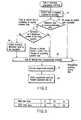
- FIG. 2 is a flowchart illustrating the operation of programming the recording of data, executed by the recording/reproducing apparatus of the present invention.
- the microcomputer block 30 determines, upon activation of the programmed recording (i.e. immediately before the start of the programmed recording), whether or not a drive used as a recording destination, such as the hard disk drive 20 or the DVD-RAM disk drive 35, etc., is currently being accessed by another task for the transfer or copying of recorded data (step S1, S2).
- the microcomputer block 30 determines the operation state of each drive with reference to, for example, a task table as shown in FIG. 3.
- task IDs (three IDs at maximum), such as recording or reproduction, etc., which are currently being executed in each of the hard disk drive and the DVD-RAM drive.
- Data "00" in the task table indicates that no task is being executed, data "01” indicates, for example, that the drive is accessed by the task of copying.
- the hard disk drive 20 can simultaneously be accessed by two tasks. In other words, apparently, the hard disk drive 20 can simultaneously execute, for example, recording and reproduction. When the drive 20 is simultaneously accessed by two tasks, data "10" indicative of this state is stored.
- step S5 If a recording-destination drive is not used to execute another task of transferring or copying recorded data, the control program proceeds to step S5, where the starting time of programmed recording is waited for. If, on the other hand, the recording-destination drive is executing another task of transferring or copying recorded data, it is determined whether or not realtime recording can be executed by simultaneous access, to the recording-destination drive, of the task of executing the programmed recording and another task, i.e. whether or not realtime recording is possible in this state (step S3).
- the control program proceeds to the step S5, where the starting time of programmed recording is waited for.
- the microcomputer block 30 enables the recording-destination drive to record programmed video data by suspending or forcibly finishing another task which is now using the drive (step S4).
- the microcomputer block 30 activates the recording-destination drive to execute the programmed recording, i.e. to record a set TV program (step S6). After finishing the programmed recording and confirming that the recording-destination drive has shifted to a recordable state, the microcomputer block 30 executes a programmed-recording finishing process (step S7). At this time, if there is any other task suspended to execute the programmed recording, the microcomputer block 30 restarts the task. In other words, the microcomputer block 30 restarts the task of transferring or copying recorded data, using the recording-destination drive.
Landscapes
- Engineering & Computer Science (AREA)
- Multimedia (AREA)
- Signal Processing (AREA)
- Signal Processing For Digital Recording And Reproducing (AREA)
- Television Signal Processing For Recording (AREA)
- Management Or Editing Of Information On Record Carriers (AREA)
- Indexing, Searching, Synchronizing, And The Amount Of Synchronization Travel Of Record Carriers (AREA)
Applications Claiming Priority (2)
| Application Number | Priority Date | Filing Date | Title |
|---|---|---|---|
| JP2000340819A JP3607597B2 (ja) | 2000-11-08 | 2000-11-08 | 記録再生装置 |
| JP2000340819 | 2000-11-08 |
Publications (2)
| Publication Number | Publication Date |
|---|---|
| EP1206136A2 true EP1206136A2 (de) | 2002-05-15 |
| EP1206136A3 EP1206136A3 (de) | 2005-03-23 |
Family
ID=18815674
Family Applications (1)
| Application Number | Title | Priority Date | Filing Date |
|---|---|---|---|
| EP01126441A Withdrawn EP1206136A3 (de) | 2000-11-08 | 2001-11-08 | Vorrichtung und Verfahren zur Videodatenaufzeichnung |
Country Status (3)
| Country | Link |
|---|---|
| US (1) | US20020057895A1 (de) |
| EP (1) | EP1206136A3 (de) |
| JP (1) | JP3607597B2 (de) |
Cited By (1)
| Publication number | Priority date | Publication date | Assignee | Title |
|---|---|---|---|---|
| CN108271432A (zh) * | 2016-11-08 | 2018-07-10 | 深圳市大疆创新科技有限公司 | 视频录制方法、装置及拍摄设备 |
Families Citing this family (8)
| Publication number | Priority date | Publication date | Assignee | Title |
|---|---|---|---|---|
| US7558472B2 (en) | 2000-08-22 | 2009-07-07 | Tivo Inc. | Multimedia signal processing system |
| US6233389B1 (en) | 1998-07-30 | 2001-05-15 | Tivo, Inc. | Multimedia time warping system |
| US8577205B2 (en) | 1998-07-30 | 2013-11-05 | Tivo Inc. | Digital video recording system |
| WO2001022729A1 (en) | 1999-09-20 | 2001-03-29 | Tivo, Inc. | Closed caption tagging system |
| CA2588630C (en) | 2004-11-19 | 2013-08-20 | Tivo Inc. | Method and apparatus for secure transfer of previously broadcasted content |
| KR100703801B1 (ko) * | 2005-10-21 | 2007-04-06 | 삼성전자주식회사 | Av 태스크 계산 방법, av 태스크 계산을 위한 요약정보 제공 방법 및 이를 위한 장치 |
| JP2007306521A (ja) * | 2006-05-15 | 2007-11-22 | Toshiba Corp | 映像記録装置 |
| JP4772738B2 (ja) * | 2007-04-26 | 2011-09-14 | 株式会社東芝 | 記録再生装置、記録再生システム、および記録再生方法 |
Family Cites Families (3)
| Publication number | Priority date | Publication date | Assignee | Title |
|---|---|---|---|---|
| JP3107073B2 (ja) * | 1998-12-03 | 2000-11-06 | 日本電気株式会社 | 情報記録再生システム |
| JP2000184320A (ja) * | 1998-12-11 | 2000-06-30 | Nec Corp | 記録再生装置および電子番組ガイド表示装置 |
| JP2000187924A (ja) * | 1998-12-18 | 2000-07-04 | Matsushita Electric Ind Co Ltd | 記録再生装置及びプログラム記録媒体 |
-
2000
- 2000-11-08 JP JP2000340819A patent/JP3607597B2/ja not_active Expired - Fee Related
-
2001
- 2001-11-07 US US09/986,199 patent/US20020057895A1/en not_active Abandoned
- 2001-11-08 EP EP01126441A patent/EP1206136A3/de not_active Withdrawn
Cited By (2)
| Publication number | Priority date | Publication date | Assignee | Title |
|---|---|---|---|---|
| CN108271432A (zh) * | 2016-11-08 | 2018-07-10 | 深圳市大疆创新科技有限公司 | 视频录制方法、装置及拍摄设备 |
| CN108271432B (zh) * | 2016-11-08 | 2020-12-29 | 深圳市大疆创新科技有限公司 | 视频录制方法、装置及拍摄设备 |
Also Published As
| Publication number | Publication date |
|---|---|
| US20020057895A1 (en) | 2002-05-16 |
| EP1206136A3 (de) | 2005-03-23 |
| JP3607597B2 (ja) | 2005-01-05 |
| JP2002152640A (ja) | 2002-05-24 |
Similar Documents
| Publication | Publication Date | Title |
|---|---|---|
| EP1254456B1 (de) | Multimedia-fotoalben | |
| EP1097450B1 (de) | Benutzerschnittstelle für digitales videogerät | |
| JP3912922B2 (ja) | 記録媒体と記録装置及び再生装置、記録方法及び再生方法 | |
| JP2002152636A (ja) | 自動チャプタ作成機能付き記録再生装置 | |
| US20030223140A1 (en) | Recording device and recording method | |
| EP1206136A2 (de) | Vorrichtung und Verfahren zur Videodatenaufzeichnung | |
| EP1213927B1 (de) | Digitale Aufnahme- und Wiedergabevorrichtung mit eingebautem Speichermedium | |
| US7474835B2 (en) | Disc playback apparatus and disc playback method | |
| EP1206138B1 (de) | Verfahren und Vorrichtung zur Videodatenaufzeichnung und -wiedergabe | |
| JP2002223411A (ja) | ディスク再生装置 | |
| EP1241668A2 (de) | Verfahren und Gerät zur Bildaufzeichnung und -wiedergabe für eine Vielzahl von Medien | |
| US7493013B2 (en) | Information storage medium having a program chain command table structure | |
| JP2001006330A (ja) | 記録媒体再生装置 | |
| EP1241666A2 (de) | Informationsaufzeichnung/wiedergabegerät | |
| JP4359910B2 (ja) | 蓄積メディアに蓄積された複数のデータ・ユニットを処理するシステムを制御する方法 | |
| JP2004071080A (ja) | 情報再生出力装置、方法、プログラム及び記録媒体 | |
| JP2005109742A (ja) | コンテンツの記録装置、コンテンツの再生装置、コンテンツの記録再生装置及びコンテンツの削除管理方法。 | |
| JP2008287820A (ja) | 光ディスク再生装置及び光ディスク再生装置の制御方法 | |
| JP4309312B2 (ja) | コンテンツ記録再生装置及びコンテンツ管理方法。 | |
| JP3887372B2 (ja) | 再生装置 | |
| JP2004357331A (ja) | 記録再生装置 | |
| JP2003244613A (ja) | 映像データ記録再生装置及び映像データ記録再生方法 | |
| JP2003109297A (ja) | フォーマット変換装置及びフォーマット変換方法 | |
| KR19980058859A (ko) | 광디스크 시스템의 예약 방법 | |
| JP2009037684A (ja) | 記録読取装置 |
Legal Events
| Date | Code | Title | Description |
|---|---|---|---|
| PUAI | Public reference made under article 153(3) epc to a published international application that has entered the european phase |
Free format text: ORIGINAL CODE: 0009012 |
|
| 17P | Request for examination filed |
Effective date: 20011108 |
|
| AK | Designated contracting states |
Kind code of ref document: A2 Designated state(s): AT BE CH CY DE DK ES FI FR GB GR IE IT LI LU MC NL PT SE TR |
|
| AX | Request for extension of the european patent |
Free format text: AL;LT;LV;MK;RO;SI |
|
| PUAL | Search report despatched |
Free format text: ORIGINAL CODE: 0009013 |
|
| AK | Designated contracting states |
Kind code of ref document: A3 Designated state(s): AT BE CH CY DE DK ES FI FR GB GR IE IT LI LU MC NL PT SE TR |
|
| AX | Request for extension of the european patent |
Extension state: AL LT LV MK RO SI |
|
| AKX | Designation fees paid |
Designated state(s): DE FR GB |
|
| STAA | Information on the status of an ep patent application or granted ep patent |
Free format text: STATUS: THE APPLICATION IS DEEMED TO BE WITHDRAWN |
|
| 18D | Application deemed to be withdrawn |
Effective date: 20090603 |