EP1205350B1 - Lenkstockschalter, insbesondere für Fahrzeuge - Google Patents
Lenkstockschalter, insbesondere für Fahrzeuge Download PDFInfo
- Publication number
- EP1205350B1 EP1205350B1 EP01120601A EP01120601A EP1205350B1 EP 1205350 B1 EP1205350 B1 EP 1205350B1 EP 01120601 A EP01120601 A EP 01120601A EP 01120601 A EP01120601 A EP 01120601A EP 1205350 B1 EP1205350 B1 EP 1205350B1
- Authority
- EP
- European Patent Office
- Prior art keywords
- steering column
- contact
- column switch
- switch
- housing
- Prior art date
- Legal status (The legal status is an assumption and is not a legal conclusion. Google has not performed a legal analysis and makes no representation as to the accuracy of the status listed.)
- Expired - Lifetime
Links
Images


Classifications
-
- B—PERFORMING OPERATIONS; TRANSPORTING
- B60—VEHICLES IN GENERAL
- B60Q—ARRANGEMENT OF SIGNALLING OR LIGHTING DEVICES, THE MOUNTING OR SUPPORTING THEREOF OR CIRCUITS THEREFOR, FOR VEHICLES IN GENERAL
- B60Q1/00—Arrangement of optical signalling or lighting devices, the mounting or supporting thereof or circuits therefor
- B60Q1/02—Arrangement of optical signalling or lighting devices, the mounting or supporting thereof or circuits therefor the devices being primarily intended to illuminate the way ahead or to illuminate other areas of way or environments
- B60Q1/04—Arrangement of optical signalling or lighting devices, the mounting or supporting thereof or circuits therefor the devices being primarily intended to illuminate the way ahead or to illuminate other areas of way or environments the devices being headlights
- B60Q1/14—Arrangement of optical signalling or lighting devices, the mounting or supporting thereof or circuits therefor the devices being primarily intended to illuminate the way ahead or to illuminate other areas of way or environments the devices being headlights having dimming means
- B60Q1/1446—Arrangement of optical signalling or lighting devices, the mounting or supporting thereof or circuits therefor the devices being primarily intended to illuminate the way ahead or to illuminate other areas of way or environments the devices being headlights having dimming means controlled by mechanically actuated switches
- B60Q1/1453—Hand actuated switches
- B60Q1/1461—Multifunction switches for dimming headlights and controlling additional devices, e.g. for controlling direction indicating lights
-
- H—ELECTRICITY
- H05—ELECTRIC TECHNIQUES NOT OTHERWISE PROVIDED FOR
- H05K—PRINTED CIRCUITS; CASINGS OR CONSTRUCTIONAL DETAILS OF ELECTRIC APPARATUS; MANUFACTURE OF ASSEMBLAGES OF ELECTRICAL COMPONENTS
- H05K1/00—Printed circuits
- H05K1/02—Details
- H05K1/0284—Details of three-dimensional rigid printed circuit boards
-
- H—ELECTRICITY
- H05—ELECTRIC TECHNIQUES NOT OTHERWISE PROVIDED FOR
- H05K—PRINTED CIRCUITS; CASINGS OR CONSTRUCTIONAL DETAILS OF ELECTRIC APPARATUS; MANUFACTURE OF ASSEMBLAGES OF ELECTRICAL COMPONENTS
- H05K3/00—Apparatus or processes for manufacturing printed circuits
- H05K3/10—Apparatus or processes for manufacturing printed circuits in which conductive material is applied to the insulating support in such a manner as to form the desired conductive pattern
- H05K3/20—Apparatus or processes for manufacturing printed circuits in which conductive material is applied to the insulating support in such a manner as to form the desired conductive pattern by affixing prefabricated conductor pattern
- H05K3/202—Apparatus or processes for manufacturing printed circuits in which conductive material is applied to the insulating support in such a manner as to form the desired conductive pattern by affixing prefabricated conductor pattern using self-supporting metal foil pattern
Definitions
- the invention relates to a steering column switch, in particular for motor vehicles with a base housing with bottom and side walls, with a housing cover, with a plurality of switch units and with the switch units contacting printed conductors.
- Such steering column switches are used in particular in motor vehicle construction. They usually have a central opening in which in the assembled state, the steering column of the motor vehicle is arranged. Furthermore, the steering column switches provide various operating levers over which the person operating the motor vehicle can perform switching functions. Such switching functions are performed via separately arranged on the steering column switch or integrated into the steering column switch switch units.
- the switch units serve, for example, for switching on and off of a motor vehicle lighting, for switching of vehicle turn signals, windscreen wiping devices, a vehicle horn, a multifunction display, a vehicle cruise control or the like.
- the steering column switch usually has a plurality of actuating levers. For electrical supply of the switching units, it is necessary to provide electrical conductors in the steering column switch.
- a steering column switch has become known, which discloses a housing with a bottom and side walls. A lid closes the inside of the switch from above.
- a sheet metal blank is embedded by encapsulation, from which a plurality of conductor tracks are punched and has received a U-shaped prior to encapsulation.
- a switch assembly with a housing having two shells.
- One of the shells comprises a plate, to which in particular a contact block for a lock, fuses and a plug outlet is provided.
- the present invention has for its object to provide a steering column switch, which in spite of the presence of a plurality of switch units in a simple manner can be mounted and in particular contacted.
- a contact grid which is not only formed in one plane, accounts within the steering column switch existing cable strands, for example, connects a switch unit of the steering column switch with an associated, existing at another point of the steering column switch plug contacts.
- Another advantage of the invention is that, in particular, the break-through, which is usually present centrally on the steering column switch, does not constitute an obstacle to the printed conductors or to the contact grid, since in this central region, for example, it can extend over sections of the side walls of the basic housing.
- the housing cover at least partially covers the outside of at least one side wall of the base housing. This has the particular advantage that strip conductors can not necessarily run within the steering column switch, but also, for example, on the outer surface of a side wall. By covering the areas in which the tracks on the outside of the main body of the steering column switch run, these are protected by the housing cover. As a result, in particular a more flexible design of the entire steering column switch is possible.
- At least one switch unit is arranged wholly or partly on the outer side of the base housing on the basic housing of the steering column switch.
- space is saved within the basic housing, whereby the entire steering column switch is smaller executable.
- switch units or their parts are mounted on the outside of the base housing, the assembly process of the entire steering column switch can be substantially simplified. An assembly from the outside can take place along a straight axis. As a result, enormous costs can be saved especially in mass production.
- a particularly advantageous embodiment of the invention provides that the housing cover at least partially covers the outer sides of the base housing, to which, for example, switch units are arranged wholly or partially. As a result, arranged on the outside of the main housing switch units or their parts are covered by the housing cover protective after their installation.
- the contact grid has free contact ends in the form of connector strands. This eliminates additional components that would be arranged for contacting connector elements to the conductors.
- a contact grid has been found that extends over portions of the bottom of the base housing as well as over portions of the side walls of the main body and has all the connector strands in one area or on one side of the steering column switch. This has the advantage that all to be contacted with the steering column switch cable strands are ceremonistecken on only one side of the steering column switch on the connector strands. It is also conceivable that only a plug can be provided which includes all connector strands. This is for contacting the steering column switch with, for example, a central control unit only one Connect plug element with the steering column switch or with the free contact ends in the form of connector strands.
- the contact grid is at least partially formed in the base housing.
- a further embodiment of the invention provides that at least one side wall of the base housing has freeforming in the region of the contact grid.
- Such Freiformstellen can arise in particular due to a forming of the contact grid.
- Particularly advantageous such Freiformstellen can be covered protectively with a housing cover.
- the contact grid is separated at predicted locations.
- Separating points are protected by the housing cover protective.
- a further, likewise preferred embodiment of the invention provides that on the inside of the base housing in the region of the contact grid accessible contact points are present, which are run over by a contacting carriage having a contact bridge.
- the contact grid is in this case directly part of an integrated in the steering column switch switching unit. This eliminates additional components, such as, for example, a switch board, which provides such contact points.
- a steering column switch thus has a total of a smaller number of components and can therefore be made very compact.
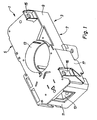
- the Indian FIG. 1 illustrated steering column switch 1 has a base housing 3 and a patch on the base housing 3 housing cover 5.
- the basic housing comprises a bottom 7 and two side walls 9 on the longitudinal sides and two side walls 11 on the transverse sides.
- the Lenstockschalter 1 has in its central region a substantially cylindrical opening 13, in which in the assembled state, the steering column of a motor vehicle is arranged.
- the housing cover 5 On its upper side, the housing cover 5 has two fastening sections 15 and 16, via which further components, such as, for example, a steering angle sensor, can be connected to the steering column switch 1.
- Fig. 1 clearly shows that the side wall 9 covering portion 17 of the housing cover 5 is almost half of the in Fig. 1 to see side wall 9 extends.
- the base housing 3 each provides a recess 19. Through the recess 19 projects in fully assembled state of the steering column switch 1 each have a shift lever, via which the steering column switch 1 can be actuated.
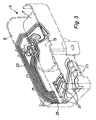
- Fig. 2 shows the bottom of the steering column switch 1 and the in Fig. 1 unseen back. It can be clearly seen that the in Fig. 1 not to be seen side wall 9 is almost completely covered by a portion 21 of the housing cover 5.
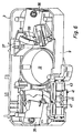
- Fig. 3 shows the base housing 3 in an implied manner, in which strip conductors in the form of a multi-part contact grid 23 extend. It can be seen that the contact grid 23 extends over portions of the bottom 7 of the base housing 3 as well as over portions of a side wall 9. Advantageously, the contact grid 23 is formed in the base housing 3.
- a further contact grid 27 is arranged in the base housing 3, which extends only in the bottom 7 of the housing cover 5. This contact grid 27 is provided for electrical contacting of switch units, which in Fig. 3 are arranged to the left of the central aperture.
- Fig. 4 shows a similar view of the basic housing 3 as Fig. 3 , However, the basic housing 3 is in Fig. 4 shown completely, so that the grid 23 and 27 are visible only at the exposed locations.
- the uncovered in the bottom 27 of the base housing 3 points 29 and 31 of the contact grid 23 and 27 are run over in the fully assembled state of the steering column switch 1 by contact bridges, not shown. Depending on the position of the contact bridges results in a planned switching position.
- Another exposed location 33 of the contact grid 23 is present on the inside of the base housing 3. In this uncovered point 33 is run over in the fully assembled state of a contact bridge having a contact carriage.
- contrast bridges or the contact slides having the contrast bridges are in this case actuated directly or indirectly by the ends of the shift lever protruding through the recesses 19 in the steering column switch 1.
- Fig. 5 illustrated cross section through the base housing 3 and the housing cover 5 clearly shows that the housing cover 5 with its sections 17 and 21 covers the base housing in the region of the side walls 9. Clear the two uncovered points 29 and 31 can also be seen Fig. 5 are no components of the arranged in or on the steering column switch 1 switch units shown.
- the housing cover the base body 3 encompassing portions 51.
- the housing cover 5 When mounting the housing cover 5 with the base body 3, the housing cover 5 is pushed axially to the longitudinal axis of the opening 13 on the base body 3. In this case, the encompassing sections 51 of the housing cover 5 pass into guide webs 53 arranged on the basic housing.
- FIG. 6 shows the base housing 3 with therein driver elements 35, which serve to accommodate the can be arranged on the steering column switch 1 shift lever. At the contact points 29 and 31 facing sides of the driver elements 35 are not provided to see contact carriage with corresponding contact bridges.
- a contact carriage 37 In the area of the contact point 33 is in Fig. 6 a contact carriage 37 is shown.
- the contact carriage 37 has on its the driver element 35 side facing a driving web 39, via which the contact carriage 37 can be actuated by the driver element 35.
- Fig. 6 further provides a switch unit 41 which comprises a plastic socket 43 with three spring tongues 45 arranged therein. At the spring tongues in each case a movable contact 47 is arranged, which can be brought via a control cam, not shown, with corresponding fixed contacts 50 in contact.
- the plastic socket 43 can be attached to the base housing 3 along a straight mounting direction from the outside of the housing.
- Fig. 7 covers the portion 17 of the housing cover 3, the plastic socket 43 including spring tongues 45 in the assembled state.
- the connector strands 25 of the contact grid 23 can be seen.
- free ends 49 of the other contact grid 27 can be seen.
Landscapes
- Engineering & Computer Science (AREA)
- Mechanical Engineering (AREA)
- Steering Controls (AREA)
- Switch Cases, Indication, And Locking (AREA)
- Switches With Compound Operations (AREA)
Applications Claiming Priority (2)
| Application Number | Priority Date | Filing Date | Title |
|---|---|---|---|
| DE10056665A DE10056665C5 (de) | 2000-11-10 | 2000-11-10 | Lenkstockschalter, insbesondere für Fahrzeuge |
| DE10056665 | 2000-11-10 |
Publications (3)
| Publication Number | Publication Date |
|---|---|
| EP1205350A2 EP1205350A2 (de) | 2002-05-15 |
| EP1205350A3 EP1205350A3 (de) | 2005-06-15 |
| EP1205350B1 true EP1205350B1 (de) | 2008-10-01 |
Family
ID=7663433
Family Applications (1)
| Application Number | Title | Priority Date | Filing Date |
|---|---|---|---|
| EP01120601A Expired - Lifetime EP1205350B1 (de) | 2000-11-10 | 2001-08-29 | Lenkstockschalter, insbesondere für Fahrzeuge |
Country Status (4)
| Country | Link |
|---|---|
| EP (1) | EP1205350B1 (es) |
| AT (1) | ATE409615T1 (es) |
| DE (2) | DE10056665C5 (es) |
| ES (1) | ES2312389T3 (es) |
Families Citing this family (4)
| Publication number | Priority date | Publication date | Assignee | Title |
|---|---|---|---|---|
| DE10252379A1 (de) * | 2002-11-12 | 2004-05-27 | Valeo Schalter Und Sensoren Gmbh | Lenkstockschalter |
| DE10330489A1 (de) | 2003-07-01 | 2005-01-27 | Valeo Schalter Und Sensoren Gmbh | Lenkstockmodul für ein Fahrzeug |
| EP3139711B1 (de) | 2015-09-03 | 2020-05-06 | SMR Patents S.à.r.l. | Elektronikvorrichtung und rückblickvorrichtung |
| US10723293B2 (en) | 2015-09-03 | 2020-07-28 | SMR Patents S.à.r.l. | Electronic device and rear-view device |
Family Cites Families (11)
| Publication number | Priority date | Publication date | Assignee | Title |
|---|---|---|---|---|
| JPS642342Y2 (es) * | 1979-10-24 | 1989-01-19 | ||
| DE4204372C2 (de) * | 1992-02-14 | 1994-07-07 | Kostal Leopold Gmbh & Co Kg | Elektrischer Schalter und Verfahren zur Herstellung |
| US5691519A (en) * | 1993-03-25 | 1997-11-25 | Eaton Corporation | Electric switch, for use on automotive steering column switch |
| JP3038639B2 (ja) * | 1994-03-30 | 2000-05-08 | ナイルス部品株式会社 | レバースイッチの組付構造 |
| JP3217234B2 (ja) * | 1995-04-11 | 2001-10-09 | ナイルス部品株式会社 | 車両用レバースイッチの構造 |
| US5602427A (en) * | 1995-07-28 | 1997-02-11 | Dimitriev; Risto E. | Vehicle lighting switch |
| US5977494A (en) * | 1995-09-08 | 1999-11-02 | Yazaki Corporation | Symmetrically mounted switches on steering wheel column body including wiring connection and control unit |
| FR2747834B1 (fr) * | 1996-04-22 | 1998-07-10 | Magneti Marelli France | Commutateur electrique pour la commande d'eclairage de vehicules automobiles |
| US5952633A (en) * | 1996-12-20 | 1999-09-14 | Eaton Corporation | Steering column stalk switch for use with multiplexed electronic switching |
| JPH10199375A (ja) * | 1997-01-17 | 1998-07-31 | Yazaki Corp | コンビネーションスイッチ装置 |
| JP3622877B2 (ja) * | 1997-02-28 | 2005-02-23 | 矢崎総業株式会社 | コンビネーションスイッチ |
-
2000
- 2000-11-10 DE DE10056665A patent/DE10056665C5/de not_active Expired - Lifetime
-
2001
- 2001-08-29 AT AT01120601T patent/ATE409615T1/de not_active IP Right Cessation
- 2001-08-29 ES ES01120601T patent/ES2312389T3/es not_active Expired - Lifetime
- 2001-08-29 EP EP01120601A patent/EP1205350B1/de not_active Expired - Lifetime
- 2001-08-29 DE DE50114360T patent/DE50114360D1/de not_active Expired - Fee Related
Also Published As
| Publication number | Publication date |
|---|---|
| DE50114360D1 (de) | 2008-11-13 |
| DE10056665A1 (de) | 2002-06-06 |
| ATE409615T1 (de) | 2008-10-15 |
| ES2312389T3 (es) | 2009-03-01 |
| EP1205350A2 (de) | 2002-05-15 |
| DE10056665C5 (de) | 2008-05-08 |
| DE10056665B4 (de) | 2004-05-06 |
| EP1205350A3 (de) | 2005-06-15 |
Similar Documents
| Publication | Publication Date | Title |
|---|---|---|
| EP1197402B1 (de) | Fahrzeuglenkrad | |
| EP1557852B1 (de) | Fahrzeuglenkrad | |
| DE19801526C2 (de) | Kombinationsschaltvorrichtung | |
| DE19746621C2 (de) | Schalteranordnung | |
| DE19700376B4 (de) | Anlasser für einen Motor | |
| EP0857351B1 (de) | Schalter mit flexibler leiterfolie als ortsfester kontakt und verbindung zu anschlusskontakten | |
| DE19908385A1 (de) | Kontaktprofil für die Hornauslösung | |
| EP1300317A2 (de) | Fahrzeuglenkrad | |
| DE3827090C2 (es) | ||
| EP1205350B1 (de) | Lenkstockschalter, insbesondere für Fahrzeuge | |
| EP1072046B1 (de) | Mit steckverbinder versehene elektrische schaltung, insbesondere steuergerät für kraftfahrzeuge | |
| DE102011013180A1 (de) | Bauteil für eine Tastenanordnung einer Bedienblende | |
| WO2019121090A1 (de) | Fahrzeugtürgriff | |
| DE9212062U1 (de) | Wipptaster | |
| DE3544804C2 (es) | ||
| DE4204372C2 (de) | Elektrischer Schalter und Verfahren zur Herstellung | |
| WO1988010503A1 (en) | Electric switch, in particular steering column switch for motor vehicles | |
| EP1772314A1 (de) | Betätigungsvorrichtung für eine elektrische betriebene Signalanlage | |
| DE102006058587A1 (de) | Elektrischer Anschlusskasten | |
| DE69501364T2 (de) | Unter dem Lenkrad angebrachtes Schaltsystem für Kraftfahrzeuge | |
| WO2020212097A1 (de) | Verfahren zur herstellung eines trägermoduls und trägermodul | |
| WO2014202306A1 (de) | Schalter, verfahren zum herstellen eines schalters und elektronikmodulsystem | |
| DE3802462C2 (es) | ||
| DE19911989C2 (de) | Metallgehäuse | |
| EP0223034B1 (de) | Elektrischer Schalter, insbesondere Lenkstockschalter für Kraftfahrzeuge |
Legal Events
| Date | Code | Title | Description |
|---|---|---|---|
| PUAI | Public reference made under article 153(3) epc to a published international application that has entered the european phase |
Free format text: ORIGINAL CODE: 0009012 |
|
| AK | Designated contracting states |
Kind code of ref document: A2 Designated state(s): AT BE CH CY DE DK ES FI FR GB GR IE IT LI LU MC NL PT SE TR |
|
| AX | Request for extension of the european patent |
Free format text: AL;LT;LV;MK;RO;SI |
|
| PUAL | Search report despatched |
Free format text: ORIGINAL CODE: 0009013 |
|
| AK | Designated contracting states |
Kind code of ref document: A3 Designated state(s): AT BE CH CY DE DK ES FI FR GB GR IE IT LI LU MC NL PT SE TR |
|
| AX | Request for extension of the european patent |
Extension state: AL LT LV MK RO SI |
|
| 17P | Request for examination filed |
Effective date: 20050803 |
|
| AKX | Designation fees paid |
Designated state(s): AT BE CH CY DE DK ES FI FR GB GR IE IT LI LU MC NL PT SE TR |
|
| 17Q | First examination report despatched |
Effective date: 20051031 |
|
| GRAP | Despatch of communication of intention to grant a patent |
Free format text: ORIGINAL CODE: EPIDOSNIGR1 |
|
| GRAS | Grant fee paid |
Free format text: ORIGINAL CODE: EPIDOSNIGR3 |
|
| GRAA | (expected) grant |
Free format text: ORIGINAL CODE: 0009210 |
|
| AK | Designated contracting states |
Kind code of ref document: B1 Designated state(s): AT BE CH CY DE DK ES FI FR GB GR IE IT LI LU MC NL PT SE TR |
|
| REG | Reference to a national code |
Ref country code: GB Ref legal event code: FG4D Free format text: NOT ENGLISH |
|
| REG | Reference to a national code |
Ref country code: CH Ref legal event code: EP |
|
| REG | Reference to a national code |
Ref country code: IE Ref legal event code: FG4D Free format text: LANGUAGE OF EP DOCUMENT: GERMAN |
|
| REF | Corresponds to: |
Ref document number: 50114360 Country of ref document: DE Date of ref document: 20081113 Kind code of ref document: P |
|
| REG | Reference to a national code |
Ref country code: ES Ref legal event code: FG2A Ref document number: 2312389 Country of ref document: ES Kind code of ref document: T3 |
|
| NLV1 | Nl: lapsed or annulled due to failure to fulfill the requirements of art. 29p and 29m of the patents act | ||
| REG | Reference to a national code |
Ref country code: IE Ref legal event code: FD4D |
|
| PG25 | Lapsed in a contracting state [announced via postgrant information from national office to epo] |
Ref country code: PT Free format text: LAPSE BECAUSE OF FAILURE TO SUBMIT A TRANSLATION OF THE DESCRIPTION OR TO PAY THE FEE WITHIN THE PRESCRIBED TIME-LIMIT Effective date: 20090302 Ref country code: NL Free format text: LAPSE BECAUSE OF FAILURE TO SUBMIT A TRANSLATION OF THE DESCRIPTION OR TO PAY THE FEE WITHIN THE PRESCRIBED TIME-LIMIT Effective date: 20081001 Ref country code: FI Free format text: LAPSE BECAUSE OF FAILURE TO SUBMIT A TRANSLATION OF THE DESCRIPTION OR TO PAY THE FEE WITHIN THE PRESCRIBED TIME-LIMIT Effective date: 20081001 |
|
| PG25 | Lapsed in a contracting state [announced via postgrant information from national office to epo] |
Ref country code: DK Free format text: LAPSE BECAUSE OF FAILURE TO SUBMIT A TRANSLATION OF THE DESCRIPTION OR TO PAY THE FEE WITHIN THE PRESCRIBED TIME-LIMIT Effective date: 20081001 Ref country code: IE Free format text: LAPSE BECAUSE OF FAILURE TO SUBMIT A TRANSLATION OF THE DESCRIPTION OR TO PAY THE FEE WITHIN THE PRESCRIBED TIME-LIMIT Effective date: 20081001 |
|
| PLBE | No opposition filed within time limit |
Free format text: ORIGINAL CODE: 0009261 |
|
| STAA | Information on the status of an ep patent application or granted ep patent |
Free format text: STATUS: NO OPPOSITION FILED WITHIN TIME LIMIT |
|
| PG25 | Lapsed in a contracting state [announced via postgrant information from national office to epo] |
Ref country code: SE Free format text: LAPSE BECAUSE OF FAILURE TO SUBMIT A TRANSLATION OF THE DESCRIPTION OR TO PAY THE FEE WITHIN THE PRESCRIBED TIME-LIMIT Effective date: 20090101 |
|
| 26N | No opposition filed |
Effective date: 20090702 |
|
| BERE | Be: lapsed |
Owner name: VALEO SCHALTER UND SENSOREN G.M.B.H. Effective date: 20090831 |
|
| PG25 | Lapsed in a contracting state [announced via postgrant information from national office to epo] |
Ref country code: MC Free format text: LAPSE BECAUSE OF NON-PAYMENT OF DUE FEES Effective date: 20090831 |
|
| REG | Reference to a national code |
Ref country code: CH Ref legal event code: PL |
|
| GBPC | Gb: european patent ceased through non-payment of renewal fee |
Effective date: 20090829 |
|
| PG25 | Lapsed in a contracting state [announced via postgrant information from national office to epo] |
Ref country code: CH Free format text: LAPSE BECAUSE OF NON-PAYMENT OF DUE FEES Effective date: 20090831 Ref country code: LI Free format text: LAPSE BECAUSE OF NON-PAYMENT OF DUE FEES Effective date: 20090831 |
|
| PG25 | Lapsed in a contracting state [announced via postgrant information from national office to epo] |
Ref country code: BE Free format text: LAPSE BECAUSE OF NON-PAYMENT OF DUE FEES Effective date: 20090831 |
|
| PG25 | Lapsed in a contracting state [announced via postgrant information from national office to epo] |
Ref country code: DE Free format text: LAPSE BECAUSE OF NON-PAYMENT OF DUE FEES Effective date: 20100302 |
|
| REG | Reference to a national code |
Ref country code: ES Ref legal event code: FD2A Effective date: 20090831 |
|
| PG25 | Lapsed in a contracting state [announced via postgrant information from national office to epo] |
Ref country code: GR Free format text: LAPSE BECAUSE OF FAILURE TO SUBMIT A TRANSLATION OF THE DESCRIPTION OR TO PAY THE FEE WITHIN THE PRESCRIBED TIME-LIMIT Effective date: 20090102 |
|
| PG25 | Lapsed in a contracting state [announced via postgrant information from national office to epo] |
Ref country code: GB Free format text: LAPSE BECAUSE OF NON-PAYMENT OF DUE FEES Effective date: 20090829 Ref country code: AT Free format text: LAPSE BECAUSE OF NON-PAYMENT OF DUE FEES Effective date: 20090829 |
|
| PG25 | Lapsed in a contracting state [announced via postgrant information from national office to epo] |
Ref country code: LU Free format text: LAPSE BECAUSE OF NON-PAYMENT OF DUE FEES Effective date: 20090829 |
|
| PG25 | Lapsed in a contracting state [announced via postgrant information from national office to epo] |
Ref country code: TR Free format text: LAPSE BECAUSE OF FAILURE TO SUBMIT A TRANSLATION OF THE DESCRIPTION OR TO PAY THE FEE WITHIN THE PRESCRIBED TIME-LIMIT Effective date: 20081001 |
|
| PG25 | Lapsed in a contracting state [announced via postgrant information from national office to epo] |
Ref country code: CY Free format text: LAPSE BECAUSE OF FAILURE TO SUBMIT A TRANSLATION OF THE DESCRIPTION OR TO PAY THE FEE WITHIN THE PRESCRIBED TIME-LIMIT Effective date: 20081001 |
|
| PG25 | Lapsed in a contracting state [announced via postgrant information from national office to epo] |
Ref country code: ES Free format text: LAPSE BECAUSE OF NON-PAYMENT OF DUE FEES Effective date: 20090830 |
|
| REG | Reference to a national code |
Ref country code: FR Ref legal event code: PLFP Year of fee payment: 16 |
|
| REG | Reference to a national code |
Ref country code: FR Ref legal event code: PLFP Year of fee payment: 17 |
|
| PGFP | Annual fee paid to national office [announced via postgrant information from national office to epo] |
Ref country code: IT Payment date: 20170809 Year of fee payment: 17 |
|
| REG | Reference to a national code |
Ref country code: FR Ref legal event code: PLFP Year of fee payment: 18 |
|
| PG25 | Lapsed in a contracting state [announced via postgrant information from national office to epo] |
Ref country code: IT Free format text: LAPSE BECAUSE OF NON-PAYMENT OF DUE FEES Effective date: 20180829 |
|
| PGFP | Annual fee paid to national office [announced via postgrant information from national office to epo] |
Ref country code: FR Payment date: 20200831 Year of fee payment: 20 |