EP1205320B1 - Clapet pour un tuyau d'écoulement - Google Patents
Clapet pour un tuyau d'écoulement Download PDFInfo
- Publication number
- EP1205320B1 EP1205320B1 EP01126096A EP01126096A EP1205320B1 EP 1205320 B1 EP1205320 B1 EP 1205320B1 EP 01126096 A EP01126096 A EP 01126096A EP 01126096 A EP01126096 A EP 01126096A EP 1205320 B1 EP1205320 B1 EP 1205320B1
- Authority
- EP
- European Patent Office
- Prior art keywords
- damper
- flap
- damper blade
- gate
- flow duct
- Prior art date
- Legal status (The legal status is an assumption and is not a legal conclusion. Google has not performed a legal analysis and makes no representation as to the accuracy of the status listed.)
- Expired - Lifetime
Links
Images

Classifications
-
- B—PERFORMING OPERATIONS; TRANSPORTING
- B60—VEHICLES IN GENERAL
- B60H—ARRANGEMENTS OF HEATING, COOLING, VENTILATING OR OTHER AIR-TREATING DEVICES SPECIALLY ADAPTED FOR PASSENGER OR GOODS SPACES OF VEHICLES
- B60H1/00—Heating, cooling or ventilating [HVAC] devices
- B60H1/00642—Control systems or circuits; Control members or indication devices for heating, cooling or ventilating devices
- B60H1/00664—Construction or arrangement of damper doors
- B60H1/00692—Damper doors moved by translation, e.g. curtain doors
-
- B—PERFORMING OPERATIONS; TRANSPORTING
- B60—VEHICLES IN GENERAL
- B60H—ARRANGEMENTS OF HEATING, COOLING, VENTILATING OR OTHER AIR-TREATING DEVICES SPECIALLY ADAPTED FOR PASSENGER OR GOODS SPACES OF VEHICLES
- B60H1/00—Heating, cooling or ventilating [HVAC] devices
- B60H1/00642—Control systems or circuits; Control members or indication devices for heating, cooling or ventilating devices
- B60H1/00664—Construction or arrangement of damper doors
-
- F—MECHANICAL ENGINEERING; LIGHTING; HEATING; WEAPONS; BLASTING
- F24—HEATING; RANGES; VENTILATING
- F24F—AIR-CONDITIONING; AIR-HUMIDIFICATION; VENTILATION; USE OF AIR CURRENTS FOR SCREENING
- F24F13/00—Details common to, or for air-conditioning, air-humidification, ventilation or use of air currents for screening
- F24F13/08—Air-flow control members, e.g. louvres, grilles, flaps or guide plates
- F24F13/10—Air-flow control members, e.g. louvres, grilles, flaps or guide plates movable, e.g. dampers
- F24F13/14—Air-flow control members, e.g. louvres, grilles, flaps or guide plates movable, e.g. dampers built up of tilting members, e.g. louvre
- F24F13/1426—Air-flow control members, e.g. louvres, grilles, flaps or guide plates movable, e.g. dampers built up of tilting members, e.g. louvre characterised by actuating means
- F24F2013/1473—Air-flow control members, e.g. louvres, grilles, flaps or guide plates movable, e.g. dampers built up of tilting members, e.g. louvre characterised by actuating means with cams or levers
Definitions
- the invention relates to a flow channel flap according to the preamble of claim 1.
- this flow channel flap an associated flap wing is movable by actuating means between a shut-off the flow channel closing position and this releasing position.
- the flap wing is guided by sliding guide means, wherein the sliding guide means and the actuating means are designed so that the flap wing when moving from the closed position to the release position and vice versa each performs a combined transverse and pivotal movement and, when it assumes its release position, side by side the closable by him channel opening is located.
- flaps are for example in flow channels of vehicle air conditioning equipment, such as heating and air conditioning systems, usable.
- the slotted guide means comprise two separate, curved running, channel housing side slide tracks, one of which is mainly along a side region of the shut-off of the flap channel opening and the other transverse thereto extends along a laterally adjacent to the opening portion in which the flap wing is in its release position.
- the slide guide means comprise two slide pins, which engage in each one of the two slide tracks, with respect to the flap wing movement direction opposite side portions of the flap wing.
- a third pivot on the flap wing engages in a slot designed as a slot path, which is introduced into a pivot arm, via which the flap wing is actuated, wherein the associated actuating means further comprises a rotatably coupled to the pivot arm gear sector and a cooperating with the latter rack.
- the actuating and slide guide means are coordinated so that the flap wing moves away from the shut-off initially with a parallel to the plane of the closed-off main component of the opening edge-side attacks, which then increasingly uses the pivoting movement component.
- Patent EP 0 732 231 B1 discloses a flow channel flap according to the preamble of claim 1, which serves as a fresh air / recirculation flap of a vehicle air conditioning device, with its flap wing between a position in which it shuts off a fresh air intake passage, and a position in which it shuts off a recirculation air intake passage , is adjustable in a combined transversal and pivotal movement. This is done so that an air intake fan facing side region of the damper blade performs a substantially rectilinear motion and thereby constantly moved very close to the fan.
- the flap wing is provided at its opposite side region with a slide track into which engages a housing-side pin on two opposite sides of the housing.
- a flap wing-side pin engages in a slot guide in the free end of the swing arm.
- the flap-wing-side pin engages in a housing-side slide track which is of a substantially circular shape.
- the invention is based on the technical problem of providing a flow channel flap of the type mentioned, which can be moved with an advantageous movement kinematics between its closed and its release position, preferably without disturbing frictional resistance between the housing and flap wing, and in which the flap wing with relatively little Keep force in the closed position.
- the invention solves this problem by providing a flow channel flap with the features of claim 1.
- the actuating and the slide guide means are specially designed so that they move the flap wing when actuated from its shut-off initially with a perpendicular to the channel opening main component of the combined transversal / pivotal movement, which is a transversal or Schwenkschiskomponente can act perpendicular to the channel opening plane.
- a special design of the slide guide means and the actuating means is provided such that a rearward in the direction of release position portion of the damper blade is guided by the slide guide means substantially linear, while the actuating means at one of them spaced, attack front flap wing area.
- This design can be realized with little effort and allows a relatively simple movement kinematics, which allows a complete moving out of the damper blade from the channel opening cross-section.
- the actuating means include a pivot arm, at the free end of the flap wing is pivotally articulated, which is a simultaneously simple and favorable in terms of motion kinematics design.
- the flap wing can be articulated indirectly via a connecting lever to the rotatable pivot arm, as indicated in claim 3.
- the pivot arm and the connecting lever occupy a stretched position to each other when the flap wing is in the closed position, which in turn minimizes the required counter-holding forces and a channel opening plane substantially vertical initial pivotal movement component allows the flap wing when moving it out of its closed position.
- the actuating means include a gear-rack coupling, in the same time a further link guide is integrated.
- the further slotted guide on an L-shape which causes the flap wing is first pivoted when moving out of its closed position, primarily, substantially perpendicular to the channel opening plane, before a significant Transversalterrorismskomponente begins.
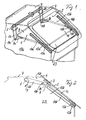
- the Fig. 1 to 4 show a flow channel flap, which acts as a fresh air inlet flap of a heating or air conditioning system of a vehicle and is actuated by a Schwenkarman extract.
- the flap includes a movable flap wing 1 for selectively blocking or releasing a fresh air inlet opening 2 of a fresh air channel 23.
- the flap wing 1 is slightly larger than the cross section of the closable by him opening 2 and lies in a in Fig. 2 shown closure position 1a at all its four edge sides from the inside against the edge 3 of the opening 2, which is formed as well as the fresh air duct 23 in the other defining walls by appropriate design of an associated fresh air duct housing 4.
- the flap wing 1 is between its the opening 2 completely shut off closing position 1a and a in Fig. 4 shown, the opening 2 completely releasing release position 1c, in which the flap wing is laterally above the outside of the opening cross-section, adjustable by a combined transverse and pivotal movement, which is defined by suitably selected actuating and sliding guide means.
- actuating means are provided for this purpose, which comprise a shaft, which can not be shown in greater detail in a conventional manner 5, which extends transversely along the inside of an upper channel housing wall 7 and on which two opposing pivot arms 6a, 6b are rotatably mounted.
- the flap wing 1 is articulated on each extension 8a, 8b on an Anschumble Scheme 9 on both sides in the form of a hinge connection 10a, 10b at the free end of the respective pivot arm 6a, 6b.
- This Anlenkmond Scheme 9 of the flap wing 1 is the front in the direction of release position 1c of the four wing side areas.
- the flap wing 1 is provided on each side with an extension 12a, 12b, from which a respective pivot pin 13a, 13b projects transversely outwards.
- the two slide pins 13a, 13b engage in a respective rectilinear slide track 14a, 14b, which are introduced at two opposite transverse boundary walls 15a, 15b and form the sliding guide means with the cooperating slide pins 13a, 13b.
- the two slide tracks 14a, 14b are approximately parallel, i. at an angle of less than about 10 ° to the plane of the fresh air opening 2 to be shut off at a small distance therefrom.
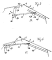
- the movement kinematics effected with these actuating and sliding guide means can be determined from the Fig. 2 to 4 good, which show the flap wing 1 in the two end positions and an intermediate position.
- the actuating means via the pivot arms 6b the flap wing against the edge 3 of the port 2 to be shut off safely and also withstand any back pressure that can act on the flap wing in its closed position 1a especially at high speeds of the vehicle.
- This main initial pivotal movement component is initially superimposed only a slight transversal motion component of the two pivot pins 13a, 13b along their slide tracks 14a, 14b. With increasing further pivotal movement of the pivot arms 6a, 6b, the transverse movement proportion increases, while the pivoting motion component decreases.
- Fig. 3 shows the flap in an approximately half-open position in which the slide pins 13a, 13b have already covered over half of the slide track length.
- the flap wing In the course of the flap movement until reaching the fully open position, ie the release position 1c of the damper blade, the latter is moved mainly transversely with only a small amount of pivoting motion.
- Fig. 4 shows the flap wing, when it is in its release position 1c, completely outside the opening cross-section of the fresh air opening 2.
- the complete movement away the flap wing 1 in the release position 1c laterally adjacent to the opening 2 thus allows optimal use of the opening cross section, which in terms on the usually tight space for such fresh air butterfly valves of vehicle air conditioning facilities is low. Since the flap wing is in the open state outside of the passing through the opening 2 air flow, it causes no cross-sectional loss and no disturbing flow noise. On the other hand, the flap wing locks in its closed position 1a, the opening 2 safely.
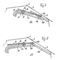
- FIGS. 1 to 4 show a further embodiment, which differs from that of the FIGS. 1 to 4 different in the type of actuation means. Otherwise, the correspond both flap arrangements, so that so far for the functionally corresponding components like reference numerals are used and with respect to the description of these components and their function in the above description of the FIGS. 1 to 4 can be referenced.
- the gear 16 is rotatably mounted in a conventional manner, not shown in detail on a user-actuated shaft 18, which in a likewise conventional, not shown in detail manner analogous to the shaft 5 of the example of Fig. 1 to 4 is rotatably held on the fresh air duct housing 4.
- the shaft 18 also serves as a crank pin, which engages through an L-shaped slide track 19 which is introduced along an upper side of the rack member 17. With a parallel distance to this L-shaped slide track 19, a likewise L-shaped tooth line 20 is formed on the rack member 17, with which the toothing of the gear 16 cooperates.
- the flap wing 1 On the rack member 17, the flap wing 1 is fixed on the upper side in a region spaced from the L-shaped arch region in such a way that it extends substantially parallel to the elongate part of the rack element 17 adjoining the L-shaped arc region.
- the fixation takes place at a location opposite the height of the wing-side pivot pins 13a, 13b spaced point of the flap wing. 1
- This choice of actuation and slotted guide means has a to that of the example of Fig. 1 to 4 essentially similar motion kinematics for adjusting the flap wing 1 between its in Fig. 6 shown closed position 1a and its in Fig. 8 shown release position 1c result.
- the L-shaped arc portion of the tooth line 20 and the associated slide track 19 in the rack member 17 acts on the gear 16 and the rack member 17 applied clamping force advantageously substantially perpendicular to the opening plane on the flap wing, so that a possible back pressure can be counteracted from the outside with a correspondingly low counter-holding force to hold the flap wing in its closed position 1a.
- the gear 16 is rotated in the arrow direction D shown, whereby initially the rack member 17 with the flap wing substantially perpendicularly moved away from the opening plane in a main pivoting component about the wing-side slide pins 13a, 13b and consequently the flap wing is lifted without significant transverse component and thus without disturbing frictional resistance from the opening edge 3.
- Fig. 7 shows for better understanding an intermediate position 1b of the flap wing, in which it opens the opening 2 barely half.
- Fig. 8 is located in this embodiment, the flap wing when it assumes its release position 1c, as well as its associated actuating means completely outside the effective flow cross-section of the opening 2, which the above to the embodiment of Fig. 1 to 4 mentioned advantages, in particular with regard to utilization of the channel cross-section and noise minimization.
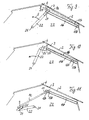
- the actuating means in the embodiment include the Fig. 9 to 11 on each of the two channel transverse sides, of which only one is shown for simplicity, depending on a housing side pivotally hinged about an axis of rotation 21 pivot arm 22 to which the flap wing is coupled via a connecting lever 24, wherein the connecting lever 24 to a with the free end of the Swing arm 22 and on the other hand with an extension 25 of the flap wing is pivotally connected.
- the two lateral extensions 25 are in turn formed on the front in the direction of the release position 1c side region 9 of the damper wing.
- the lever coupling of the flap wing is selected so that the connecting lever 24 is located in the extension line of the pivot arm 22 when the flap wing in its closed position 1a according to Fig. 9 located.
- this special design of the actuating means together with the slide guide means in this embodiment the result that the flap wing is moved out of its closed position 1a to open with a substantially perpendicular to the opening plane movement from its closed position and thus stands out without significant friction resistance from the opening edge 3 , Only after the flap wing in this way with a main pivotal movement component to the two slide pins, of which in the Fig. 9 to 11 only one pin 13b can be seen, moved out of the closed position 1a and thereby a in Fig. 10 shown intermediate position has taken 1b with partial opening release, it is spent by the further course of the rotational movement of the pivot arm 22 with then stronger transverse component in its release position 1c laterally above and thus outside the cross section of the opening 2.
- the invention realizes a comparatively easy to manufacture flow channel flap whose flap wings on the one hand shut off a flow channel and on the other hand can be spent in a the opening cross-section completely releasing release position laterally adjacent to the channel opening.
- the flap wing can be held in its closed position with relatively little effort. It can be moved out of its closed position with primarily directed perpendicular to the plane of the opening movement component, which minimizes frictional resistance between the flap wing and the channel housing, especially the opening edge and there optionally arranged seals.
- flow channel flap according to the invention not only in fresh air ducts, but also in other channels of vehicle air conditioning devices and beyond in flow channels of any other devices can be used in which a channel opening of a controllable, movable flap wing is either shut off or released.
Landscapes
- Engineering & Computer Science (AREA)
- Mechanical Engineering (AREA)
- Thermal Sciences (AREA)
- Physics & Mathematics (AREA)
- Combustion & Propulsion (AREA)
- General Engineering & Computer Science (AREA)
- Chemical & Material Sciences (AREA)
- Air-Flow Control Members (AREA)
- Sliding Valves (AREA)
- Seal Device For Vehicle (AREA)
- Vehicle Step Arrangements And Article Storage (AREA)
- Infusion, Injection, And Reservoir Apparatuses (AREA)
- Check Valves (AREA)
- Mechanically-Actuated Valves (AREA)
- Structures Of Non-Positive Displacement Pumps (AREA)
Claims (6)
- Volet de conduit d'écoulement, en particulier pour un dispositif de climatisation d'un véhicule, comprenant :- une ailette de volet (1) qui est mobile entre une position de fermeture (1a) dans laquelle l'ailette de volet obture une ouverture de conduit (2) d'un conduit d'écoulement (23) défini par un carter de conduit (4), et une position d'ouverture (1c) dans laquelle l'ailette de volet ouvre l'ouverture de conduit (2),- des moyens d'actionnement (6a, 6b ; 22, 24 ; 16 - 20) qui sont couplés à l'ailette de volet (1) pour son actionnement, et- des moyens de guide de coulisse (13a, 13b, 14a, 14b) servant à guider l'ailette (1) du volet, moyens de guide de coulisse qui sont prévus d'une part sur le carter de conduit (4) et d'autre part sur l'ailette (1) du volet,où les moyens de guide de coulisse (13a, 13b, 14a, 14b) et les moyens d'actionnement (6a, 6b ; 22, 24 ; 16 - 20) sont conçus de manière telle, qu'ils déplacent l'ailette (1) du volet suivant un mouvement transversal et pivotant combiné, que l'ailette (1) du volet, dans la position d'ouverture (1c), se trouve latéralement à côté de l'ouverture de conduit (2), et que lesdits moyens de guide de coulisse et d'actionnement dégagent l'ailette (1) du volet, en cas d'actionnement pour sortir de sa position de fermeture (1a), d'abord avec un composant principal du mouvement transversal / pivotant, perpendiculaire au plan de l'ouverture du conduit,
caractérisé en ce que l'ailette (1) du volet, sur la zone latérale arrière (11) de l'ailette, dans la direction de la position d'ouverture (1c), est dotée des deux côtés, à chaque fois d'un prolongement (12a, 12b) à partir duquel fait saillie un tourillon de coulisse respectif (13a, 13b), transversalement vers l'extérieur, et que les moyens de guide de coulisse (13a, 13b, 14a, 14b) se composent de deux pistes de coulisse (14a, 14b) rectilignes placées l'une en face de l'autre par rapport au conduit d'écoulement (23), pistes de coulisse qui s'étendent à faible distance de l'ouverture de conduit, suivant un angle de moins de 10° par rapport au plan de l'ouverture de conduit (2) à obturer, et se composent des tourillons de coulisse associés (13a, 13b) s'engageant dans la piste de coulisse respective (14a, 14b), où l'ailette (1) du volet, dans une zone avant (9) de l'ailette (1) du volet, en direction de la position d'ouverture (1c), espacée de la zone de couplage des tourillons de coulisse, est couplée aux moyens d'actionnement (6a, 6b ; 22, 24 ; 16 - 20). - Volet de conduit d'écoulement selon la revendication 1, caractérisé en outre en ce que les moyens d'actionnement comportent au moins un bras pivotant (6a, 6b ; 22) sur l'extrémité libre duquel est articulée, mobile en rotation, l'ailette (1) du volet.
- Volet de conduit d'écoulement selon la revendication 2, caractérisé en outre en ce que l'ailette (1) du volet est couplée directement ou par un levier de liaison (24), à l'extrémité libre du bras pivotant (6a, 6b ; 22).
- Volet de conduit d'écoulement selon la revendication 3, caractérisé en outre en ce que le levier de liaison (24) prend une position en longueur par rapport au bras pivotant (22) lorsque l'ailette (1) du volet se trouve dans sa position de fermeture (1a).
- Volet de conduit d'écoulement selon la revendication 1, caractérisé en outre en ce que les moyens d'actionnement (16 - 20) comprennent au moins une roue dentée (16) montée solidaire en rotation sur un arbre (18), et un élément de crémaillère (17) comportant une ligne de denture (20) fonctionnant en association avec la roue dentée (16), et comprenant une autre piste de coulisse (19) dans laquelle s'engage l'arbre (18) servant d'élément de guide de coulisse.
- Volet de conduit d'écoulement selon la revendication 5, caractérisé en outre en ce que la ligne de denture (20) et l'autre piste de coulisse (19) de l'élément de crémaillère (17), correspondant à la ligne de denture, sont configurées en forme de L.
Applications Claiming Priority (2)
| Application Number | Priority Date | Filing Date | Title |
|---|---|---|---|
| DE10056670 | 2000-11-09 | ||
| DE10056670A DE10056670A1 (de) | 2000-11-09 | 2000-11-09 | Strömungskanalklappe |
Publications (3)
| Publication Number | Publication Date |
|---|---|
| EP1205320A2 EP1205320A2 (fr) | 2002-05-15 |
| EP1205320A3 EP1205320A3 (fr) | 2003-07-16 |
| EP1205320B1 true EP1205320B1 (fr) | 2009-05-13 |
Family
ID=7663436
Family Applications (1)
| Application Number | Title | Priority Date | Filing Date |
|---|---|---|---|
| EP01126096A Expired - Lifetime EP1205320B1 (fr) | 2000-11-09 | 2001-11-02 | Clapet pour un tuyau d'écoulement |
Country Status (3)
| Country | Link |
|---|---|
| EP (1) | EP1205320B1 (fr) |
| AT (1) | ATE431265T1 (fr) |
| DE (2) | DE10056670A1 (fr) |
Families Citing this family (7)
| Publication number | Priority date | Publication date | Assignee | Title |
|---|---|---|---|---|
| DE10261036A1 (de) * | 2002-07-29 | 2004-02-12 | Behr Gmbh & Co. | Klimagehäuse |
| WO2004014676A1 (fr) | 2002-07-29 | 2004-02-19 | Behr Gmbh & Co. Kg | Boitier de climatisation |
| FR2851502B1 (fr) * | 2003-02-26 | 2006-06-23 | Valeo Climatisation | Dispositif de controle d'un flux d'air, notamment pour un appareil de chauffage et/ou de climatisation d'un vehicule automobile |
| DE102004024182A1 (de) * | 2004-05-13 | 2005-12-01 | Behr Gmbh & Co. Kg | Heizungs- und/oder Klimatisierungseinrichtung für Fahrzeuge |
| US7174918B2 (en) * | 2005-02-01 | 2007-02-13 | Delphi Technologies, Inc. | Air flow control valve for vehicle air conditioning module |
| DE102007032479A1 (de) * | 2007-07-10 | 2009-01-15 | Behr Gmbh & Co. Kg | Luftverteiler- und/oder Luftmischvorrichtung |
| DE102008012349A1 (de) * | 2008-03-03 | 2009-09-10 | GM Global Technology Operations, Inc., Detroit | Heiz- bzw. Klimaanlage |
Citations (2)
| Publication number | Priority date | Publication date | Assignee | Title |
|---|---|---|---|---|
| EP0732231A1 (fr) * | 1995-03-15 | 1996-09-18 | Adam Opel Ag | Dispositif de chauffage, d'aération ou de climatisation pour véhicule automobile |
| FR2763286A1 (fr) * | 1997-05-14 | 1998-11-20 | Valeo Climatisation | Dispositif de reglage d'air pour vehicule automobile |
Family Cites Families (3)
| Publication number | Priority date | Publication date | Assignee | Title |
|---|---|---|---|---|
| DE2534652C3 (de) * | 1975-08-02 | 1980-10-30 | Philips Patentverwaltung Gmbh, 2000 Hamburg | Schwenkgetriebe zum Verschwenken eines Bauteiles gegenüber einem feststehenden Gehäuse |
| DE4415459B4 (de) * | 1994-05-03 | 2006-11-09 | Valeo Climatisation S.A. | Vorrichtung zum Betätigen einer Klappe |
| FR2756901B1 (fr) * | 1996-12-09 | 1999-02-12 | Valeo Climatisation | Dispositif de commande d'un volet de reglage d'air pour une installation de chauffage-ventilation et/ou climatisation de vehicule automobile |
-
2000
- 2000-11-09 DE DE10056670A patent/DE10056670A1/de not_active Withdrawn
-
2001
- 2001-11-02 DE DE50114891T patent/DE50114891D1/de not_active Expired - Lifetime
- 2001-11-02 AT AT01126096T patent/ATE431265T1/de not_active IP Right Cessation
- 2001-11-02 EP EP01126096A patent/EP1205320B1/fr not_active Expired - Lifetime
Patent Citations (2)
| Publication number | Priority date | Publication date | Assignee | Title |
|---|---|---|---|---|
| EP0732231A1 (fr) * | 1995-03-15 | 1996-09-18 | Adam Opel Ag | Dispositif de chauffage, d'aération ou de climatisation pour véhicule automobile |
| FR2763286A1 (fr) * | 1997-05-14 | 1998-11-20 | Valeo Climatisation | Dispositif de reglage d'air pour vehicule automobile |
Also Published As
| Publication number | Publication date |
|---|---|
| DE50114891D1 (de) | 2009-06-25 |
| DE10056670A1 (de) | 2002-05-16 |
| EP1205320A3 (fr) | 2003-07-16 |
| EP1205320A2 (fr) | 2002-05-15 |
| ATE431265T1 (de) | 2009-05-15 |
Similar Documents
| Publication | Publication Date | Title |
|---|---|---|
| DE3632058C2 (fr) | ||
| DE3124325C2 (fr) | ||
| EP1112881B1 (fr) | Dispositif de verrouillage pour toit pliant | |
| DE69411496T2 (de) | Schubumkehreinrichtung eines Turbinenstrahltriebwerk mit Hilfklappen | |
| DE4414036A1 (de) | Lufteintritt für eine Heizungs- oder Klimaanlage eines Kraftfahrzeugs | |
| DE19714105C2 (de) | Umwandelbares Fahrzeugdach | |
| DE202005015169U1 (de) | Schwenkschiebetür für Fahrzeuge, insbesondere Fahrgasttür für Fahrzeuge des öffentlichen Personennahverkehrs | |
| DE3602120C2 (fr) | ||
| EP2051878A2 (fr) | Mécanisme cinématique pour un couvercle d'un vide-poches dans un véhicule | |
| EP1270286B1 (fr) | Dispositif pour diriger l'air, notamment pour un véhicule | |
| EP1205320B1 (fr) | Clapet pour un tuyau d'écoulement | |
| DE19718091A1 (de) | Vorrichtung zum Öffnen/Schließen eines Fahrzeugfensters | |
| DE3447797A1 (de) | Einrichtung zum regeln der foerdermenge von rotationsverdichtern | |
| DE102005055700B3 (de) | Ausströmdüse für den Fahrgastraum eines Kraftfahrzeuges | |
| DE4101288A1 (de) | Spoilerdach fuer fahrzeuge | |
| DE4231639C1 (de) | Betätigungsvorrichtung für ein in zwei Endlagen umschaltbares Stellglied, insbesondere für Luftklappen | |
| DE102011056079A1 (de) | Belüftungsdüse für einen Fahrgastraum eines Fahrzeugs | |
| DE3230066C2 (de) | Öffnungs- und Schließmechanismus für ein Sonnendach eines Fahrzeuges | |
| DE10137650A1 (de) | Windabweiser für ein Fahrzeugdach | |
| DE4302504C1 (de) | Luftsteuervorrichtung | |
| DE20022692U1 (de) | Strömungskanalklappe | |
| DE102020108169A1 (de) | Luftausströmer | |
| EP0118665B1 (fr) | Tringlerie pour la commande et/ou la connexion des trappes d'une installation de chauffage, de ventilation ou de conditionnement d'air | |
| AT502965B1 (de) | Vorrichtung zur regelung der öffnungsfolge von zweiflügeligen schwenktüren | |
| EP1030019B1 (fr) | Dispositif d'arrêt mécanique pour le vantail d'une porte |
Legal Events
| Date | Code | Title | Description |
|---|---|---|---|
| PUAI | Public reference made under article 153(3) epc to a published international application that has entered the european phase |
Free format text: ORIGINAL CODE: 0009012 |
|
| AK | Designated contracting states |
Kind code of ref document: A2 Designated state(s): AT BE CH CY DE DK ES FI FR GB GR IE IT LI LU MC NL PT SE TR |
|
| AX | Request for extension of the european patent |
Free format text: AL;LT;LV;MK;RO;SI |
|
| PUAL | Search report despatched |
Free format text: ORIGINAL CODE: 0009013 |
|
| AK | Designated contracting states |
Designated state(s): AT BE CH CY DE DK ES FI FR GB GR IE IT LI LU MC NL PT SE TR |
|
| AX | Request for extension of the european patent |
Extension state: AL LT LV MK RO SI |
|
| 17P | Request for examination filed |
Effective date: 20030918 |
|
| AKX | Designation fees paid |
Designated state(s): AT BE CH CY DE DK ES FI FR GB GR IE IT LI LU MC NL PT SE TR |
|
| RAP1 | Party data changed (applicant data changed or rights of an application transferred) |
Owner name: BEHR GMBH & CO. KG |
|
| 17Q | First examination report despatched |
Effective date: 20080109 |
|
| GRAP | Despatch of communication of intention to grant a patent |
Free format text: ORIGINAL CODE: EPIDOSNIGR1 |
|
| GRAS | Grant fee paid |
Free format text: ORIGINAL CODE: EPIDOSNIGR3 |
|
| GRAA | (expected) grant |
Free format text: ORIGINAL CODE: 0009210 |
|
| AK | Designated contracting states |
Kind code of ref document: B1 Designated state(s): AT BE CH CY DE DK ES FI FR GB GR IE IT LI LU MC NL PT SE TR |
|
| REG | Reference to a national code |
Ref country code: GB Ref legal event code: FG4D Free format text: NOT ENGLISH |
|
| REG | Reference to a national code |
Ref country code: CH Ref legal event code: EP |
|
| REG | Reference to a national code |
Ref country code: IE Ref legal event code: FG4D |
|
| REF | Corresponds to: |
Ref document number: 50114891 Country of ref document: DE Date of ref document: 20090625 Kind code of ref document: P |
|
| PG25 | Lapsed in a contracting state [announced via postgrant information from national office to epo] |
Ref country code: FI Free format text: LAPSE BECAUSE OF FAILURE TO SUBMIT A TRANSLATION OF THE DESCRIPTION OR TO PAY THE FEE WITHIN THE PRESCRIBED TIME-LIMIT Effective date: 20090513 Ref country code: ES Free format text: LAPSE BECAUSE OF FAILURE TO SUBMIT A TRANSLATION OF THE DESCRIPTION OR TO PAY THE FEE WITHIN THE PRESCRIBED TIME-LIMIT Effective date: 20090824 Ref country code: PT Free format text: LAPSE BECAUSE OF FAILURE TO SUBMIT A TRANSLATION OF THE DESCRIPTION OR TO PAY THE FEE WITHIN THE PRESCRIBED TIME-LIMIT Effective date: 20090913 |
|
| NLV1 | Nl: lapsed or annulled due to failure to fulfill the requirements of art. 29p and 29m of the patents act | ||
| PG25 | Lapsed in a contracting state [announced via postgrant information from national office to epo] |
Ref country code: SE Free format text: LAPSE BECAUSE OF FAILURE TO SUBMIT A TRANSLATION OF THE DESCRIPTION OR TO PAY THE FEE WITHIN THE PRESCRIBED TIME-LIMIT Effective date: 20090813 Ref country code: NL Free format text: LAPSE BECAUSE OF FAILURE TO SUBMIT A TRANSLATION OF THE DESCRIPTION OR TO PAY THE FEE WITHIN THE PRESCRIBED TIME-LIMIT Effective date: 20090513 |
|
| REG | Reference to a national code |
Ref country code: IE Ref legal event code: FD4D |
|
| PG25 | Lapsed in a contracting state [announced via postgrant information from national office to epo] |
Ref country code: IE Free format text: LAPSE BECAUSE OF FAILURE TO SUBMIT A TRANSLATION OF THE DESCRIPTION OR TO PAY THE FEE WITHIN THE PRESCRIBED TIME-LIMIT Effective date: 20090513 Ref country code: DK Free format text: LAPSE BECAUSE OF FAILURE TO SUBMIT A TRANSLATION OF THE DESCRIPTION OR TO PAY THE FEE WITHIN THE PRESCRIBED TIME-LIMIT Effective date: 20090513 |
|
| PLBE | No opposition filed within time limit |
Free format text: ORIGINAL CODE: 0009261 |
|
| STAA | Information on the status of an ep patent application or granted ep patent |
Free format text: STATUS: NO OPPOSITION FILED WITHIN TIME LIMIT |
|
| 26N | No opposition filed |
Effective date: 20100216 |
|
| BERE | Be: lapsed |
Owner name: BEHR G.M.B.H. & CO. KG Effective date: 20091130 |
|
| PG25 | Lapsed in a contracting state [announced via postgrant information from national office to epo] |
Ref country code: MC Free format text: LAPSE BECAUSE OF NON-PAYMENT OF DUE FEES Effective date: 20091130 |
|
| REG | Reference to a national code |
Ref country code: CH Ref legal event code: PL |
|
| GBPC | Gb: european patent ceased through non-payment of renewal fee |
Effective date: 20091102 |
|
| PG25 | Lapsed in a contracting state [announced via postgrant information from national office to epo] |
Ref country code: LI Free format text: LAPSE BECAUSE OF NON-PAYMENT OF DUE FEES Effective date: 20091130 Ref country code: CH Free format text: LAPSE BECAUSE OF NON-PAYMENT OF DUE FEES Effective date: 20091130 Ref country code: BE Free format text: LAPSE BECAUSE OF NON-PAYMENT OF DUE FEES Effective date: 20091130 Ref country code: GR Free format text: LAPSE BECAUSE OF FAILURE TO SUBMIT A TRANSLATION OF THE DESCRIPTION OR TO PAY THE FEE WITHIN THE PRESCRIBED TIME-LIMIT Effective date: 20090814 |
|
| PG25 | Lapsed in a contracting state [announced via postgrant information from national office to epo] |
Ref country code: GB Free format text: LAPSE BECAUSE OF NON-PAYMENT OF DUE FEES Effective date: 20091102 |
|
| PG25 | Lapsed in a contracting state [announced via postgrant information from national office to epo] |
Ref country code: AT Free format text: LAPSE BECAUSE OF NON-PAYMENT OF DUE FEES Effective date: 20091102 |
|
| PGFP | Annual fee paid to national office [announced via postgrant information from national office to epo] |
Ref country code: FR Payment date: 20101209 Year of fee payment: 10 |
|
| PG25 | Lapsed in a contracting state [announced via postgrant information from national office to epo] |
Ref country code: IT Free format text: LAPSE BECAUSE OF FAILURE TO SUBMIT A TRANSLATION OF THE DESCRIPTION OR TO PAY THE FEE WITHIN THE PRESCRIBED TIME-LIMIT Effective date: 20090513 |
|
| PG25 | Lapsed in a contracting state [announced via postgrant information from national office to epo] |
Ref country code: LU Free format text: LAPSE BECAUSE OF NON-PAYMENT OF DUE FEES Effective date: 20091102 |
|
| PG25 | Lapsed in a contracting state [announced via postgrant information from national office to epo] |
Ref country code: TR Free format text: LAPSE BECAUSE OF FAILURE TO SUBMIT A TRANSLATION OF THE DESCRIPTION OR TO PAY THE FEE WITHIN THE PRESCRIBED TIME-LIMIT Effective date: 20090513 |
|
| PG25 | Lapsed in a contracting state [announced via postgrant information from national office to epo] |
Ref country code: CY Free format text: LAPSE BECAUSE OF FAILURE TO SUBMIT A TRANSLATION OF THE DESCRIPTION OR TO PAY THE FEE WITHIN THE PRESCRIBED TIME-LIMIT Effective date: 20090513 |
|
| REG | Reference to a national code |
Ref country code: FR Ref legal event code: ST Effective date: 20120731 |
|
| PG25 | Lapsed in a contracting state [announced via postgrant information from national office to epo] |
Ref country code: FR Free format text: LAPSE BECAUSE OF NON-PAYMENT OF DUE FEES Effective date: 20111130 |
|
| REG | Reference to a national code |
Ref country code: DE Ref legal event code: R082 Ref document number: 50114891 Country of ref document: DE Representative=s name: GRAUEL, ANDREAS, DIPL.-PHYS. DR. RER. NAT., DE |
|
| REG | Reference to a national code |
Ref country code: DE Ref legal event code: R082 Ref document number: 50114891 Country of ref document: DE Representative=s name: GRAUEL, ANDREAS, DIPL.-PHYS. DR. RER. NAT., DE Effective date: 20150306 Ref country code: DE Ref legal event code: R081 Ref document number: 50114891 Country of ref document: DE Owner name: MAHLE INTERNATIONAL GMBH, DE Free format text: FORMER OWNER: BEHR GMBH & CO. KG, 70469 STUTTGART, DE Effective date: 20150306 |
|
| PGFP | Annual fee paid to national office [announced via postgrant information from national office to epo] |
Ref country code: DE Payment date: 20181203 Year of fee payment: 18 |
|
| REG | Reference to a national code |
Ref country code: DE Ref legal event code: R119 Ref document number: 50114891 Country of ref document: DE |
|
| PG25 | Lapsed in a contracting state [announced via postgrant information from national office to epo] |
Ref country code: DE Free format text: LAPSE BECAUSE OF NON-PAYMENT OF DUE FEES Effective date: 20200603 |