EP1205320B1 - Damper for a flow duct - Google Patents
Damper for a flow duct Download PDFInfo
- Publication number
- EP1205320B1 EP1205320B1 EP01126096A EP01126096A EP1205320B1 EP 1205320 B1 EP1205320 B1 EP 1205320B1 EP 01126096 A EP01126096 A EP 01126096A EP 01126096 A EP01126096 A EP 01126096A EP 1205320 B1 EP1205320 B1 EP 1205320B1
- Authority
- EP
- European Patent Office
- Prior art keywords
- damper
- flap
- damper blade
- gate
- flow duct
- Prior art date
- Legal status (The legal status is an assumption and is not a legal conclusion. Google has not performed a legal analysis and makes no representation as to the accuracy of the status listed.)
- Expired - Lifetime
Links
Images

Classifications
-
- B—PERFORMING OPERATIONS; TRANSPORTING
- B60—VEHICLES IN GENERAL
- B60H—ARRANGEMENTS OF HEATING, COOLING, VENTILATING OR OTHER AIR-TREATING DEVICES SPECIALLY ADAPTED FOR PASSENGER OR GOODS SPACES OF VEHICLES
- B60H1/00—Heating, cooling or ventilating [HVAC] devices
- B60H1/00642—Control systems or circuits; Control members or indication devices for heating, cooling or ventilating devices
- B60H1/00664—Construction or arrangement of damper doors
- B60H1/00692—Damper doors moved by translation, e.g. curtain doors
-
- B—PERFORMING OPERATIONS; TRANSPORTING
- B60—VEHICLES IN GENERAL
- B60H—ARRANGEMENTS OF HEATING, COOLING, VENTILATING OR OTHER AIR-TREATING DEVICES SPECIALLY ADAPTED FOR PASSENGER OR GOODS SPACES OF VEHICLES
- B60H1/00—Heating, cooling or ventilating [HVAC] devices
- B60H1/00642—Control systems or circuits; Control members or indication devices for heating, cooling or ventilating devices
- B60H1/00664—Construction or arrangement of damper doors
-
- F—MECHANICAL ENGINEERING; LIGHTING; HEATING; WEAPONS; BLASTING
- F24—HEATING; RANGES; VENTILATING
- F24F—AIR-CONDITIONING; AIR-HUMIDIFICATION; VENTILATION; USE OF AIR CURRENTS FOR SCREENING
- F24F13/00—Details common to, or for air-conditioning, air-humidification, ventilation or use of air currents for screening
- F24F13/08—Air-flow control members, e.g. louvres, grilles, flaps or guide plates
- F24F13/10—Air-flow control members, e.g. louvres, grilles, flaps or guide plates movable, e.g. dampers
- F24F13/14—Air-flow control members, e.g. louvres, grilles, flaps or guide plates movable, e.g. dampers built up of tilting members, e.g. louvre
- F24F13/1426—Air-flow control members, e.g. louvres, grilles, flaps or guide plates movable, e.g. dampers built up of tilting members, e.g. louvre characterised by actuating means
- F24F2013/1473—Air-flow control members, e.g. louvres, grilles, flaps or guide plates movable, e.g. dampers built up of tilting members, e.g. louvre characterised by actuating means with cams or levers
Landscapes
- Engineering & Computer Science (AREA)
- Mechanical Engineering (AREA)
- Physics & Mathematics (AREA)
- Thermal Sciences (AREA)
- General Engineering & Computer Science (AREA)
- Combustion & Propulsion (AREA)
- Chemical & Material Sciences (AREA)
- Air-Flow Control Members (AREA)
- Seal Device For Vehicle (AREA)
- Vehicle Step Arrangements And Article Storage (AREA)
- Infusion, Injection, And Reservoir Apparatuses (AREA)
- Check Valves (AREA)
- Mechanically-Actuated Valves (AREA)
- Structures Of Non-Positive Displacement Pumps (AREA)
- Sliding Valves (AREA)
Abstract
Description
Die Erfindung bezieht sich auf eine Strömungskanalklappe nach dem Oberbegriff des Anspruchs 1. Bei dieser Strömungskanalklappe ist ein zugehöriger Klappenflügel durch Betätigungsmittel zwischen einer den Strömungskanal absperrenden Schließposition und einer diesen freigebenden Position bewegbar. Dabei wird der Klappenflügel durch Kulissenführungsmittel geführt, wobei die Kulissenführungsmittel und die Betätigungsmittel so ausgelegt sind, dass der Klappenflügel beim Verbringen von der Schließposition in die Freigabeposition und umgekehrt jeweils eine kombinierte Transversal- und Schwenkbewegung ausführt und sich, wenn er seine Freigabeposition einnimmt, seitlich neben der von ihm absperrbaren Kanalöffnung befindet. Derartige Klappen sind beispielsweise in Strömungskanälen von Fahrzeugklimatisierungseinrichtungen, wie Heizungs- und Klimaanlagen, verwendbar.The invention relates to a flow channel flap according to the preamble of claim 1. In this flow channel flap an associated flap wing is movable by actuating means between a shut-off the flow channel closing position and this releasing position. In this case, the flap wing is guided by sliding guide means, wherein the sliding guide means and the actuating means are designed so that the flap wing when moving from the closed position to the release position and vice versa each performs a combined transverse and pivotal movement and, when it assumes its release position, side by side the closable by him channel opening is located. Such flaps are for example in flow channels of vehicle air conditioning equipment, such as heating and air conditioning systems, usable.
In der
In der
Der Erfindung liegt als technisches Problem die Bereitstellung einer Strömungskanalklappe der eingangs genannten Art zugrunde, die sich mit einer vorteilhaften Bewegungskinematik zwischen ihrer Schließ- und ihrer Freigabeposition bewegen lässt, vorzugsweise ohne störende Reibwiderstände zwischen Gehäuse und Klappenflügel, und bei der sich der Klappenflügel mit relativ geringem Kraftaufwand in der Schließposition halten lässt.The invention is based on the technical problem of providing a flow channel flap of the type mentioned, which can be moved with an advantageous movement kinematics between its closed and its release position, preferably without disturbing frictional resistance between the housing and flap wing, and in which the flap wing with relatively little Keep force in the closed position.
Die Erfindung löst dieses Problem durch die Bereitstellung einer Strömungskanalklappe mit den Merkmalen des Anspruchs 1.The invention solves this problem by providing a flow channel flap with the features of claim 1.
Bei der Strömungskanalklappe nach Anspruch 1 sind die Betätigungs- und die Kulissenführungsmittel speziell so ausgelegt, dass sie den Klappenflügel bei Betätigen aus seiner Absperrposition zunächst mit einer zur Kanalöffnung senkrechten Hauptkomponente der kombinierten Transversal-/Schwenkbewegung herausbewegen, wobei es sich um eine Transversal- oder Schwenkbewegungskomponente senkrecht zur Kanalöffnungsebene handeln kann. Dies hat zum einen den Vorteil, dass sich Reib-widerstände zwischen Gehäuse und Klappenflügel beim Herausbewegen des Klappenflügels aus seiner Schließposition minimal halten lassen, und schafft zum anderen die Voraussetzung dafür, dass sich der Klappenflügel mit relativ geringem Kraftaufwand in der Schließposition halten lässt, da die Kraftübertragungsrichtung zwischen den Betätigungsmitteln und dem Klappenflügel eine zur Kanalöffnungsebene senkrechte und damit zum Strömungsdruck auf den Klappenflügel parallele Hauptkomponente aufweist.In the flow channel flap according to claim 1, the actuating and the slide guide means are specially designed so that they move the flap wing when actuated from its shut-off initially with a perpendicular to the channel opening main component of the combined transversal / pivotal movement, which is a transversal or Schwenkbewegungskomponente can act perpendicular to the channel opening plane. This has, on the one hand, the advantage that friction resistances between the housing and the flap wing can be minimized when the flap wing is moved out of its closed position, and, on the other hand, creates the prerequisite for keeping the flap wing in the closed position with relatively little effort the force transmission direction between the actuating means and the flap wing has a perpendicular to the channel opening plane and thus parallel to the flow pressure on the flap wing main component.
Dabei ist eine spezielle Gestaltung der Kulissenführungsmittel und der Betätigungsmittel derart vorgesehen, dass ein in Richtung Freigabeposition hinterer Bereich des Klappenflügels durch die Kulissenführungsmittel im wesentlichen linear geführt wird, während die Betätigungsmittel an einem davon beabstandeten, vorderen Klappenflügelbereich angreifen. Diese Gestaltung lässt sich mit geringem Aufwand realisieren und ermöglicht eine relativ einfache Bewegungskinematik, die ein vollständiges Herausbewegen des Klappenflügels aus dem Kanalöffnungsquerschnitt erlaubt.In this case, a special design of the slide guide means and the actuating means is provided such that a rearward in the direction of release position portion of the damper blade is guided by the slide guide means substantially linear, while the actuating means at one of them spaced, attack front flap wing area. This design can be realized with little effort and allows a relatively simple movement kinematics, which allows a complete moving out of the damper blade from the channel opening cross-section.
In einer vorteilhaften Ausgestaltung der Erfindung nach Anspruch 2 beinhalten die Betätigungsmittel einen Schwenkarm, an dessen freies Ende der Klappenflügel drehbeweglich angelenkt ist, was eine gleichzeitig einfache und bezüglich der Bewegungskinematik günstige Gestaltung darstellt. Alternativ zu einer direkten derartigen Anlenkung kann der Klappenflügel indirekt über einen Verbindungshebel an den drehbeweglichen Schwenkarm angelenkt sein, wie im Anspruch 3 angegeben. Bei dieser Realisierung ist weiterhin eine Auslegung gemäß Anspruch 4 von Vorteil, bei welcher der Schwenkarm und der Verbindungshebel eine gestreckte Stellung zueinander einnehmen, wenn sich der Klappenflügel in der Schließposition befindet, was wiederum die erforderlichen Gegenhaltekräfte minimiert und eine zur Kanalöffnungsebene im wesentlichen senkrechte anfängliche Schwenkbewegungskomponente des Klappenflügels beim Herausbewegen desselben aus seiner Schließposition ermöglicht.In an advantageous embodiment of the invention according to
In einer Weiterbildung der Erfindung nach Anspruch 5 beinhalten die Betätigungsmittel eine Zahnrad-Zahnstangen-Kopplung, in die gleichzeitig eine weitere Kulissenführung integriert ist. In Ausgestaltung dieser Realisierung gemäß Anspruch 6 weist die weitere Kulissenführung eine L-Form auf, die bewirkt, dass der Klappenflügel beim Herausbewegen aus seiner Schließposition zunächst primär verschwenkt wird, und zwar im wesentlichen senkrecht zur Kanalöffnungsebene, bevor eine merkliche Transversalbewegungskomponente einsetzt.In a further development of the invention according to
Vorteilhafte Ausführungsformen der Erfindung sind in den Zeichnungen dargestellt und werden nachfolgend beschrieben. Hierbei zeigen:
- Fig. 1
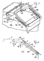
- eine Perspektivansicht einer in einen Frischluftkanal einer Fahrzeugklimatisierungseinrichtung eingebauten Strömungskanalklappe mit Schwenkarmbetätigung,
- Fig. 2
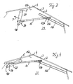
- eine Seitenansicht der Klappe von
Fig. 1 in geschlossenem Zustand, - Fig. 3
- eine Seitenansicht der Klappe von
Fig. 1 in teilweise geöffnetem Zustand, - Fig. 4
- eine Seitenansicht der Klappe von
Fig. 1 in vollständig geöffnetem Zustand, - Fig. 5
- eine Ansicht entsprechend
Fig. 1 , jedoch für eine Klappenvariante mit Zahnstangenbetätigung, - Fig. 6
- eine Seitenansicht der Klappe von
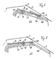
Fig. 5 in geschlossenem Zustand, - Fig. 7
- eine Seitenansicht der Klappe von
Fig. 5 in teilweise geöffnetem Zustand, - Fig. 8
- eine Seitenansicht der Klappe von
Fig. 5 in vollständig geöffnetem Zustand, - Fig. 9
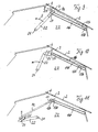
- eine Seitenansicht einer Frischluftkanalklappe, die über einen Schwenkarm und einen zusätzlichen Verbindungshebel betätigt wird, in geschlossenem Zustand,
- Fig. 10
- eine Seitenansicht der Klappe von
Fig. 9 in einer etwas von der Schließposition wegbewegten Stellung und - Fig. 11
- eine Seitenansicht der Klappe von
Fig. 9 in vollständig geöffneter Stellung.
- Fig. 1
- a perspective view of a built-in fresh air duct of a vehicle air conditioning device flow channel flap with Schwenkarmbetätigung,
- Fig. 2
- a side view of the flap of
Fig. 1 in closed condition, - Fig. 3
- a side view of the flap of
Fig. 1 in partially open condition, - Fig. 4
- a side view of the flap of
Fig. 1 in fully open condition, - Fig. 5
- a view accordingly
Fig. 1 , but for a flap variant with rack actuation, - Fig. 6
- a side view of the flap of
Fig. 5 in closed condition, - Fig. 7
- a side view of the flap of
Fig. 5 in partially open condition, - Fig. 8
- a side view of the flap of
Fig. 5 in fully open condition, - Fig. 9
- a side view of a fresh air duct flap, which is actuated via a pivoting arm and an additional connecting lever, in the closed state,
- Fig. 10
- a side view of the flap of
Fig. 9 in a slightly away from the closed position position and - Fig. 11
- a side view of the flap of
Fig. 9 in fully open position.
Die
Der Klappenflügel 1 ist zwischen seiner die Öffnung 2 vollständig absperrenden Schließposition 1a und einer in
An dem in Richtung Freigabeposition 1c hinteren Flügelseitenbereich 11 ist der Klappenflügel 1 beidseits mit je einem Fortsatz 12a, 12b versehen, von dem quer nach außen ein jeweiliger Kulissenzapfen 13a, 13b absteht. Die beiden Kulissenzapfen 13a, 13b greifen in je eine geradlinige Kulissenbahn 14a, 14b ein, die an zwei gegenüberliegenden Querbegrenzungswänden 15a, 15b eingebracht sind und mit den zusammenwirkenden Kulissenzapfen 13a, 13b die Kulissenführungsmittel bilden. Die beiden Kulissenbahnen 14a, 14b verlaufen annähernd parallel, d.h. unter einem Winkel von weniger als etwa 10°, zur Ebene der abzusperrenden Frischluftöffnung 2 mit geringem Abstand von dieser.At the rear
Die mit diesen Betätigungs- und Kulissenführungsmitteln bewirkte Bewegungskinematik lässt sich aus den
Die
Beim Ausführungsbeispiel der
Am Zahnstangenelement 17 ist oberseitig in einem vom L-förmigen Bogenbereich beabstandeten Bereich der Klappenflügel 1 derart fixiert, dass er sich im wesentlichen parallel zum an den L-förmigen Bogenbereich anschließenden, langgestreckten Teil des Zahnstangenelements 17 erstreckt. Die Fixierung erfolgt dabei an einer gegenüber der Höhe der flügelseitigen Kulissenzapfen 13a, 13b beabstandeten Stelle des Klappenflügels 1.On the
Diese Wahl der Betätigungs- und Kulissenführungsmittel hat eine zu derjenigen des Beispiels der
Zum Herausbewegen des Klappenflügels aus seiner Schließposition 1a wird das Zahnrad 16 in der gezeigten Pfeilrichtung D in Drehung versetzt, wodurch sich zunächst das Zahnstangenelement 17 mit dem Klappenflügel im wesentlichen senkrecht von der Öffnungsebene in einer hauptsächlichen Schwenkbewegungskomponente um die flügelseitigen Kulissenzapfen 13a, 13b wegbewegt und folglich der Klappenflügel ohne wesentliche Querkomponente und damit ohne störende Reibwiderstände vom Öffnungsrand 3 abgehoben wird. Im weiteren Verlauf der Öffnungsbewegung gelangen dann der L-Bogenbereich der Zahnungslinie 20 in den Wirkbereich des Zahnrads 16 und gleichzeitig der L-Bogenbereich der Kulissenbahn 19 in den Bereich der Welle 18, wodurch die Klappenflügelbewegung von der zuvor hauptsächlichen Schwenkbewegung in eine anschließende, hauptsächlich transversale Bewegung mit geringerer Schwenkbewegungskomponente übergeht, bis der Klappenflügel 1c schließlich seine Freigabeposition 1c seitlich oberhalb der Kanalöffnung 2 erreicht hat.
Wie aus
Es versteht sich, dass alternativ zu der gezeigten, in Querrichtung mittigen Positionierung eines einzelnen Zahnrades 16 mit zugehörigem Zahnstangenelement 17 zwei seitliche Zahnräder mit zwei zugehörigen Zahnstangenelementen entsprechend den beiden seitlichen Schwenkarmen 6a, 6b des Beispiels der
In den
Die Hebelankopplung des Klappenflügels ist so gewählt, dass der Verbindungshebel 24 in der Verlängerungslinie des Schwenkarms 22 liegt, wenn sich der Klappenflügel in seiner Schließposition 1a gemäß
Wie aus der obigen Beschreibung vorteilhafter Ausführungsbeispiele deutlich wird, realisiert die Erfindung eine vergleichsweise einfach herstellbare Strömungskanalklappe, deren Klappenflügel einerseits einen Strömungskanal absperren und andererseits in eine den Öffnungsquerschnitt vollständig freigebende Freigabeposition seitlich neben der Kanalöffnung verbracht werden kann. Der Klappenflügel kann mit relativ geringem Kraftaufwand in seiner Schließposition gehalten werden. Er lässt sich aus seiner Schließposition mit primär senkrecht zur Öffnungsebene gerichteter Bewegungskomponente herausbewegen, was Reibwiderstände zwischen dem Klappenflügel und dem Kanalgehäuse, speziell dem Öffnungsrand und dort gegebenenfalls angeordneten Dichtungen, minimiert.As is apparent from the above description of advantageous embodiments, the invention realizes a comparatively easy to manufacture flow channel flap whose flap wings on the one hand shut off a flow channel and on the other hand can be spent in a the opening cross-section completely releasing release position laterally adjacent to the channel opening. The flap wing can be held in its closed position with relatively little effort. It can be moved out of its closed position with primarily directed perpendicular to the plane of the opening movement component, which minimizes frictional resistance between the flap wing and the channel housing, especially the opening edge and there optionally arranged seals.
Es versteht sich, dass die erfindungsgemäße Strömungskanalklappe nicht nur in Frischluftkanälen, sondern auch in anderen Kanälen von Fahrzeugklimatisierungseinrichtungen und darüber hinaus in Strömungskanälen beliebiger anderer Einrichtungen einsetzbar ist, bei denen eine Kanalöffnung von einem ansteuerbaren, beweglichen Klappenflügel wahlweise abgesperrt oder freigegeben werden soll.It is understood that the flow channel flap according to the invention not only in fresh air ducts, but also in other channels of vehicle air conditioning devices and beyond in flow channels of any other devices can be used in which a channel opening of a controllable, movable flap wing is either shut off or released.
Claims (6)
- Damper for a flow duct, in particular for a vehicle air conditioner, comprising:- a damper blade (1) movable between a closed position (1a), in which it blocks a duct opening (2) of a flow duct (23) defined by a duct housing (4), and a release position (1c), in which it releases the duct opening (2),- operating means (6a, 6b; 22, 24; 16-20) coupled to the damper blade (1) for its operation, and- gate guidance means (13a, 13b, 14a, 14b) provided on the duct housing (4) and on the damper blade (1) for the guidance of the damper blade (1),- wherein the gate guidance means (13a, 13b, 14a, 14b) and the operating means (6a, 6b; 22, 24; 16-20) are designed such that they move the damper blade (1) in a combined transversal and swivelling movement, that the damper blade (1) is placed at the side of the duct opening (2) in its release position (1c) and that they initially move the damper blade (1) from its closed position (1a) with a main component of the transversal/swivelling movement which acts at right angles to the plane of the duct opening,characterised in that
the damper blade (1) is, in the blade side region (11) which is at the rear in the direction of the release position (1c), provided with an extension (12a, 12b) on either side, from each of which projects a gate pin (13a, 13b) transversely outwards, and in that the gate guidance means (13a, 13b, 14a, 14b) consist of two straight gate guideways (14a, 14b) disposed opposite one another relative to the flow duct (23), which extend at an angle of less than 10 degrees relative to the plane of the duct opening (2) to be blocked at a slight distance therefrom, and of the respective guide pins (13a, 13b) engaging the gate guideways (14a, 14b), wherein the damper blade (1) is coupled to the operating means (6a, 6b; 22, 24; 16-20) in a region (9) of the damper blade (1) which is at the front in the direction of the release position (1c) and placed at a distance from the gate pin coupling region. - Damper for a flow duct according to claim 1, further characterised in that the operating means include at least one swivelling arm (6a, 6b; 22), at the free end of which the damper blade (1) is rotatably hinged.
- Damper for a flow duct according to claim 2, further characterised in that the damper blade (1) is coupled to the free end of the swivelling arm (6a, 6b; 22) either directly or via a connecting lever (24).
- Damper for a flow duct according to claim 3, further characterised in that the connecting lever (24) adopts a position which extends the swivelling arm (22) if the damper blade (1) is in its closed position (1a).
- Damper for a flow duct according to claim 1, further characterised in that the operating means (16-20) include at least one gear (16) non-rotatably mounted on a shaft (18) and a rack element (17) with a tooth line (20) acting together with the gear (16) and with a further gate guideway (19), which the shaft (18) acting as a gate guidance element engages.
- Damper for a flow duct according to claim 5, further characterised in that the tooth line (20) and the corresponding further gate guideway (19) of the rack element (17) are L-shaped.
Applications Claiming Priority (2)
| Application Number | Priority Date | Filing Date | Title |
|---|---|---|---|
| DE10056670A DE10056670A1 (en) | 2000-11-09 | 2000-11-09 | Flow channel flap |
| DE10056670 | 2000-11-09 |
Publications (3)
| Publication Number | Publication Date |
|---|---|
| EP1205320A2 EP1205320A2 (en) | 2002-05-15 |
| EP1205320A3 EP1205320A3 (en) | 2003-07-16 |
| EP1205320B1 true EP1205320B1 (en) | 2009-05-13 |
Family
ID=7663436
Family Applications (1)
| Application Number | Title | Priority Date | Filing Date |
|---|---|---|---|
| EP01126096A Expired - Lifetime EP1205320B1 (en) | 2000-11-09 | 2001-11-02 | Damper for a flow duct |
Country Status (3)
| Country | Link |
|---|---|
| EP (1) | EP1205320B1 (en) |
| AT (1) | ATE431265T1 (en) |
| DE (2) | DE10056670A1 (en) |
Families Citing this family (7)
| Publication number | Priority date | Publication date | Assignee | Title |
|---|---|---|---|---|
| DE10261036A1 (en) * | 2002-07-29 | 2004-02-12 | Behr Gmbh & Co. | Air conditioning housing for motor vehicle has hot air mixing chamber and separate duct for cooling air to floor area |
| AU2003282104A1 (en) | 2002-07-29 | 2004-02-25 | Behr France S.A.R.L. | Air-conditioner housing |
| FR2851502B1 (en) * | 2003-02-26 | 2006-06-23 | Valeo Climatisation | DEVICE FOR MONITORING AN AIR FLOW, IN PARTICULAR FOR AN APPARATUS FOR HEATING AND / OR AIR CONDITIONING A MOTOR VEHICLE |
| DE102004024182A1 (en) * | 2004-05-13 | 2005-12-01 | Behr Gmbh & Co. Kg | Heating and / or air conditioning device for vehicles |
| US7174918B2 (en) | 2005-02-01 | 2007-02-13 | Delphi Technologies, Inc. | Air flow control valve for vehicle air conditioning module |
| DE102007032479A1 (en) * | 2007-07-10 | 2009-01-15 | Behr Gmbh & Co. Kg | Air distribution and / or air mixing device |
| DE102008012349A1 (en) * | 2008-03-03 | 2009-09-10 | GM Global Technology Operations, Inc., Detroit | Heating or air conditioning unit for use in motor vehicles, has flange-air inlet device, which has housing with fresh air inlet opening and air outlet opening, where recirculated air flap is arranged on outer wall of fresh air inlet opening |
Citations (2)
| Publication number | Priority date | Publication date | Assignee | Title |
|---|---|---|---|---|
| EP0732231A1 (en) * | 1995-03-15 | 1996-09-18 | Adam Opel Ag | Heating, aerationor air conditioning device for vehicle |
| FR2763286A1 (en) * | 1997-05-14 | 1998-11-20 | Valeo Climatisation | Motor vehicle heater/air-conditioner adjustment device |
Family Cites Families (3)
| Publication number | Priority date | Publication date | Assignee | Title |
|---|---|---|---|---|
| DE2534652C3 (en) * | 1975-08-02 | 1980-10-30 | Philips Patentverwaltung Gmbh, 2000 Hamburg | Swivel gear for swiveling a component in relation to a stationary housing |
| DE4415459B4 (en) * | 1994-05-03 | 2006-11-09 | Valeo Climatisation S.A. | Device for actuating a flap |
| FR2756901B1 (en) * | 1996-12-09 | 1999-02-12 | Valeo Climatisation | DEVICE FOR CONTROLLING AN AIR ADJUSTMENT SHUTTER FOR A VENTILATION HEATING AND / OR AIR CONDITIONING VEHICLE INSTALLATION |
-
2000
- 2000-11-09 DE DE10056670A patent/DE10056670A1/en not_active Withdrawn
-
2001
- 2001-11-02 DE DE50114891T patent/DE50114891D1/en not_active Expired - Lifetime
- 2001-11-02 AT AT01126096T patent/ATE431265T1/en not_active IP Right Cessation
- 2001-11-02 EP EP01126096A patent/EP1205320B1/en not_active Expired - Lifetime
Patent Citations (2)
| Publication number | Priority date | Publication date | Assignee | Title |
|---|---|---|---|---|
| EP0732231A1 (en) * | 1995-03-15 | 1996-09-18 | Adam Opel Ag | Heating, aerationor air conditioning device for vehicle |
| FR2763286A1 (en) * | 1997-05-14 | 1998-11-20 | Valeo Climatisation | Motor vehicle heater/air-conditioner adjustment device |
Also Published As
| Publication number | Publication date |
|---|---|
| EP1205320A3 (en) | 2003-07-16 |
| DE50114891D1 (en) | 2009-06-25 |
| DE10056670A1 (en) | 2002-05-16 |
| ATE431265T1 (en) | 2009-05-15 |
| EP1205320A2 (en) | 2002-05-15 |
Similar Documents
| Publication | Publication Date | Title |
|---|---|---|
| DE3124325C2 (en) | ||
| DE3632058C2 (en) | ||
| EP1112881B1 (en) | Locking device for foldable top | |
| DE4414036A1 (en) | Air inlet for a heating or air conditioning system of a motor vehicle | |
| DE19714105C2 (en) | Convertible vehicle roof | |
| DE202005015169U1 (en) | Sliding sliding door for vehicles, in particular passenger door for public transport vehicles | |
| DE3602120C2 (en) | ||
| WO2008022733A2 (en) | Kinematics for a cover of an oddments tray in a vehicle | |
| EP1270286B1 (en) | Air directing device especially for a vehicle | |
| EP1205320B1 (en) | Damper for a flow duct | |
| EP2759669B1 (en) | Hinge for a cooking oven | |
| DE19718091A1 (en) | Opening and closing mechanism for car window with pinion and gear segment | |
| DE3447797A1 (en) | DEVICE FOR REGULATING THE FLOW RATE OF ROTATIONAL COMPRESSORS | |
| EP1118491A2 (en) | Pivoting vehicle door wing, in particular for buses | |
| DE102005055700B3 (en) | Air outlet of ventilation unit for vehicle, comprises swivel mounted cover and linear movable fins | |
| DE4101288A1 (en) | Combined car sliding roof and spoiler - has actuating mechanism with swivel arm with rotary drive pinion at one end, rotating about parallel axis | |
| DE4231639C1 (en) | Actuator for operating air control-flap of cooling- or air- conditioning-system - has linear actuator with transmission having cam track shaped to give high force at start and end | |
| DE3230066C2 (en) | Opening and closing mechanism for a sunroof of a vehicle | |
| DE10137650A1 (en) | Wind deflector for motor vehicle roof has common driven control element for deflector body adjusting levers | |
| DE4302504C1 (en) | Air control device for heating, air-conditioning or ventilation systems in road vehicles - has air guide channel in which is pivotable air valve for controlling air throughput cross-section | |
| EP0118665B1 (en) | Rods for the actuation and/or connection of flaps of a heating, ventilating or air conditioning installation | |
| AT502965B1 (en) | DEVICE FOR REGULATING THE OPENING OF DOUBLE LEVER DOORS | |
| EP1030019B1 (en) | Mechanical holding device for a door-wing | |
| DE10110014A1 (en) | Drive arrangement for an element of a vehicle roof that can be pivoted for storage in a storage space in a vehicle | |
| DE19846159C1 (en) | Openable roof for motor vehicle |
Legal Events
| Date | Code | Title | Description |
|---|---|---|---|
| PUAI | Public reference made under article 153(3) epc to a published international application that has entered the european phase |
Free format text: ORIGINAL CODE: 0009012 |
|
| AK | Designated contracting states |
Kind code of ref document: A2 Designated state(s): AT BE CH CY DE DK ES FI FR GB GR IE IT LI LU MC NL PT SE TR |
|
| AX | Request for extension of the european patent |
Free format text: AL;LT;LV;MK;RO;SI |
|
| PUAL | Search report despatched |
Free format text: ORIGINAL CODE: 0009013 |
|
| AK | Designated contracting states |
Designated state(s): AT BE CH CY DE DK ES FI FR GB GR IE IT LI LU MC NL PT SE TR |
|
| AX | Request for extension of the european patent |
Extension state: AL LT LV MK RO SI |
|
| 17P | Request for examination filed |
Effective date: 20030918 |
|
| AKX | Designation fees paid |
Designated state(s): AT BE CH CY DE DK ES FI FR GB GR IE IT LI LU MC NL PT SE TR |
|
| RAP1 | Party data changed (applicant data changed or rights of an application transferred) |
Owner name: BEHR GMBH & CO. KG |
|
| 17Q | First examination report despatched |
Effective date: 20080109 |
|
| GRAP | Despatch of communication of intention to grant a patent |
Free format text: ORIGINAL CODE: EPIDOSNIGR1 |
|
| GRAS | Grant fee paid |
Free format text: ORIGINAL CODE: EPIDOSNIGR3 |
|
| GRAA | (expected) grant |
Free format text: ORIGINAL CODE: 0009210 |
|
| AK | Designated contracting states |
Kind code of ref document: B1 Designated state(s): AT BE CH CY DE DK ES FI FR GB GR IE IT LI LU MC NL PT SE TR |
|
| REG | Reference to a national code |
Ref country code: GB Ref legal event code: FG4D Free format text: NOT ENGLISH |
|
| REG | Reference to a national code |
Ref country code: CH Ref legal event code: EP |
|
| REG | Reference to a national code |
Ref country code: IE Ref legal event code: FG4D |
|
| REF | Corresponds to: |
Ref document number: 50114891 Country of ref document: DE Date of ref document: 20090625 Kind code of ref document: P |
|
| PG25 | Lapsed in a contracting state [announced via postgrant information from national office to epo] |
Ref country code: FI Free format text: LAPSE BECAUSE OF FAILURE TO SUBMIT A TRANSLATION OF THE DESCRIPTION OR TO PAY THE FEE WITHIN THE PRESCRIBED TIME-LIMIT Effective date: 20090513 Ref country code: ES Free format text: LAPSE BECAUSE OF FAILURE TO SUBMIT A TRANSLATION OF THE DESCRIPTION OR TO PAY THE FEE WITHIN THE PRESCRIBED TIME-LIMIT Effective date: 20090824 Ref country code: PT Free format text: LAPSE BECAUSE OF FAILURE TO SUBMIT A TRANSLATION OF THE DESCRIPTION OR TO PAY THE FEE WITHIN THE PRESCRIBED TIME-LIMIT Effective date: 20090913 |
|
| NLV1 | Nl: lapsed or annulled due to failure to fulfill the requirements of art. 29p and 29m of the patents act | ||
| PG25 | Lapsed in a contracting state [announced via postgrant information from national office to epo] |
Ref country code: SE Free format text: LAPSE BECAUSE OF FAILURE TO SUBMIT A TRANSLATION OF THE DESCRIPTION OR TO PAY THE FEE WITHIN THE PRESCRIBED TIME-LIMIT Effective date: 20090813 Ref country code: NL Free format text: LAPSE BECAUSE OF FAILURE TO SUBMIT A TRANSLATION OF THE DESCRIPTION OR TO PAY THE FEE WITHIN THE PRESCRIBED TIME-LIMIT Effective date: 20090513 |
|
| REG | Reference to a national code |
Ref country code: IE Ref legal event code: FD4D |
|
| PG25 | Lapsed in a contracting state [announced via postgrant information from national office to epo] |
Ref country code: IE Free format text: LAPSE BECAUSE OF FAILURE TO SUBMIT A TRANSLATION OF THE DESCRIPTION OR TO PAY THE FEE WITHIN THE PRESCRIBED TIME-LIMIT Effective date: 20090513 Ref country code: DK Free format text: LAPSE BECAUSE OF FAILURE TO SUBMIT A TRANSLATION OF THE DESCRIPTION OR TO PAY THE FEE WITHIN THE PRESCRIBED TIME-LIMIT Effective date: 20090513 |
|
| PLBE | No opposition filed within time limit |
Free format text: ORIGINAL CODE: 0009261 |
|
| STAA | Information on the status of an ep patent application or granted ep patent |
Free format text: STATUS: NO OPPOSITION FILED WITHIN TIME LIMIT |
|
| 26N | No opposition filed |
Effective date: 20100216 |
|
| BERE | Be: lapsed |
Owner name: BEHR G.M.B.H. & CO. KG Effective date: 20091130 |
|
| PG25 | Lapsed in a contracting state [announced via postgrant information from national office to epo] |
Ref country code: MC Free format text: LAPSE BECAUSE OF NON-PAYMENT OF DUE FEES Effective date: 20091130 |
|
| REG | Reference to a national code |
Ref country code: CH Ref legal event code: PL |
|
| GBPC | Gb: european patent ceased through non-payment of renewal fee |
Effective date: 20091102 |
|
| PG25 | Lapsed in a contracting state [announced via postgrant information from national office to epo] |
Ref country code: LI Free format text: LAPSE BECAUSE OF NON-PAYMENT OF DUE FEES Effective date: 20091130 Ref country code: CH Free format text: LAPSE BECAUSE OF NON-PAYMENT OF DUE FEES Effective date: 20091130 Ref country code: BE Free format text: LAPSE BECAUSE OF NON-PAYMENT OF DUE FEES Effective date: 20091130 Ref country code: GR Free format text: LAPSE BECAUSE OF FAILURE TO SUBMIT A TRANSLATION OF THE DESCRIPTION OR TO PAY THE FEE WITHIN THE PRESCRIBED TIME-LIMIT Effective date: 20090814 |
|
| PG25 | Lapsed in a contracting state [announced via postgrant information from national office to epo] |
Ref country code: GB Free format text: LAPSE BECAUSE OF NON-PAYMENT OF DUE FEES Effective date: 20091102 |
|
| PG25 | Lapsed in a contracting state [announced via postgrant information from national office to epo] |
Ref country code: AT Free format text: LAPSE BECAUSE OF NON-PAYMENT OF DUE FEES Effective date: 20091102 |
|
| PGFP | Annual fee paid to national office [announced via postgrant information from national office to epo] |
Ref country code: FR Payment date: 20101209 Year of fee payment: 10 |
|
| PG25 | Lapsed in a contracting state [announced via postgrant information from national office to epo] |
Ref country code: IT Free format text: LAPSE BECAUSE OF FAILURE TO SUBMIT A TRANSLATION OF THE DESCRIPTION OR TO PAY THE FEE WITHIN THE PRESCRIBED TIME-LIMIT Effective date: 20090513 |
|
| PG25 | Lapsed in a contracting state [announced via postgrant information from national office to epo] |
Ref country code: LU Free format text: LAPSE BECAUSE OF NON-PAYMENT OF DUE FEES Effective date: 20091102 |
|
| PG25 | Lapsed in a contracting state [announced via postgrant information from national office to epo] |
Ref country code: TR Free format text: LAPSE BECAUSE OF FAILURE TO SUBMIT A TRANSLATION OF THE DESCRIPTION OR TO PAY THE FEE WITHIN THE PRESCRIBED TIME-LIMIT Effective date: 20090513 |
|
| PG25 | Lapsed in a contracting state [announced via postgrant information from national office to epo] |
Ref country code: CY Free format text: LAPSE BECAUSE OF FAILURE TO SUBMIT A TRANSLATION OF THE DESCRIPTION OR TO PAY THE FEE WITHIN THE PRESCRIBED TIME-LIMIT Effective date: 20090513 |
|
| REG | Reference to a national code |
Ref country code: FR Ref legal event code: ST Effective date: 20120731 |
|
| PG25 | Lapsed in a contracting state [announced via postgrant information from national office to epo] |
Ref country code: FR Free format text: LAPSE BECAUSE OF NON-PAYMENT OF DUE FEES Effective date: 20111130 |
|
| REG | Reference to a national code |
Ref country code: DE Ref legal event code: R082 Ref document number: 50114891 Country of ref document: DE Representative=s name: GRAUEL, ANDREAS, DIPL.-PHYS. DR. RER. NAT., DE |
|
| REG | Reference to a national code |
Ref country code: DE Ref legal event code: R082 Ref document number: 50114891 Country of ref document: DE Representative=s name: GRAUEL, ANDREAS, DIPL.-PHYS. DR. RER. NAT., DE Effective date: 20150306 Ref country code: DE Ref legal event code: R081 Ref document number: 50114891 Country of ref document: DE Owner name: MAHLE INTERNATIONAL GMBH, DE Free format text: FORMER OWNER: BEHR GMBH & CO. KG, 70469 STUTTGART, DE Effective date: 20150306 |
|
| PGFP | Annual fee paid to national office [announced via postgrant information from national office to epo] |
Ref country code: DE Payment date: 20181203 Year of fee payment: 18 |
|
| REG | Reference to a national code |
Ref country code: DE Ref legal event code: R119 Ref document number: 50114891 Country of ref document: DE |
|
| PG25 | Lapsed in a contracting state [announced via postgrant information from national office to epo] |
Ref country code: DE Free format text: LAPSE BECAUSE OF NON-PAYMENT OF DUE FEES Effective date: 20200603 |