EP1205317A2 - Communication de capteur de condition de pneumatique avec réception avec amplification à rapport cyclique du côté du pneumatique - Google Patents
Communication de capteur de condition de pneumatique avec réception avec amplification à rapport cyclique du côté du pneumatique Download PDFInfo
- Publication number
- EP1205317A2 EP1205317A2 EP01126688A EP01126688A EP1205317A2 EP 1205317 A2 EP1205317 A2 EP 1205317A2 EP 01126688 A EP01126688 A EP 01126688A EP 01126688 A EP01126688 A EP 01126688A EP 1205317 A2 EP1205317 A2 EP 1205317A2
- Authority
- EP
- European Patent Office
- Prior art keywords
- tire condition
- sensor unit
- tire
- control signal
- vehicle
- Prior art date
- Legal status (The legal status is an assumption and is not a legal conclusion. Google has not performed a legal analysis and makes no representation as to the accuracy of the status listed.)
- Granted
Links
Images

Classifications
-
- B—PERFORMING OPERATIONS; TRANSPORTING
- B60—VEHICLES IN GENERAL
- B60C—VEHICLE TYRES; TYRE INFLATION; TYRE CHANGING; CONNECTING VALVES TO INFLATABLE ELASTIC BODIES IN GENERAL; DEVICES OR ARRANGEMENTS RELATED TO TYRES
- B60C23/00—Devices for measuring, signalling, controlling, or distributing tyre pressure or temperature, specially adapted for mounting on vehicles; Arrangement of tyre inflating devices on vehicles, e.g. of pumps or of tanks; Tyre cooling arrangements
- B60C23/02—Signalling devices actuated by tyre pressure
- B60C23/04—Signalling devices actuated by tyre pressure mounted on the wheel or tyre
- B60C23/0408—Signalling devices actuated by tyre pressure mounted on the wheel or tyre transmitting the signals by non-mechanical means from the wheel or tyre to a vehicle body mounted receiver
- B60C23/0422—Signalling devices actuated by tyre pressure mounted on the wheel or tyre transmitting the signals by non-mechanical means from the wheel or tyre to a vehicle body mounted receiver characterised by the type of signal transmission means
- B60C23/0433—Radio signals
Definitions
- the present invention relates to a tire condition monitoring system for providing tire operation parameter information, such as tire inflation pressure, to a vehicle operator and for providing tire location identification regardless of previous tire position change due to tire position rotation or the like.
- the present invention relates specifically to a tire condition monitoring system that provides for positive communication control between a vehicle-based unit and tire sensor units to avoid lost communication and the like.
- tire condition monitoring systems have been developed in order to provide tire operation information to a vehicle operator.
- One example type of a tire condition monitoring system is a tire pressure monitoring system that detects when air pressure within a tire drops below a predetermined threshold pressure value.
- a run-flat tire enables a vehicle to travel an extended distance after significant loss of air pressure within that tire.
- a vehicle operator may have difficulty recognizing the significant loss of air pressure within the tire because the loss of air pressure may cause little change in vehicle handling and little change in the visual appearance of the tire.
- a tire pressure monitoring system typically includes a pressure sensing device, such as a pressure switch, an internal power source, and a communications link that provides the tire pressure information from a location at each tire to a central receiver unit.
- the central receiver unit is typically connected to an indicator or display located on a vehicle instrument panel.
- the communications link between each tire-based unit and the central receiver unit is often a wireless link.
- radio frequency signals are utilized to transmit information from each of the tire-based units to the central receiver unit.
- some form of identification of the origin of the signal must be utilized. A need for identification of the origin of the transmitted tire information signal becomes especially important subsequent to a tire position change, such as tire position rotation during routine maintenance.
- the communications link between a tire-based unit and the central receiver may be disrupted. Such disruption may occur due to simultaneous. communication from two tire-based units, multi-path interference from a single transmission, or rotating e-field created by tire movement.
- Positive control of all of the communication that occurs within a system could have very desirable benefits, such as avoiding communication disruption or repeating disrupted communication.
- an ability of one unit to control another unit(s) is often thought of as being associated with the application and consumption of power (e.g., electrical power).
- power e.g., electrical power
- the present invention provides a tire condition sensor unit for association with a tire of a vehicle and for communicating a tire condition to a vehicle-based unit.
- Sensor means senses the tire condition.
- Transmitter means operatively connected to the sensor means, transmits a condition signal that indicates the sensed tire condition.
- Receiver means operatively connected to the sensor means and the transmitter means, receives a control signal and causes operation of the sensor means and the transmitter means during receipt of the control signal.
- the present invention provides a tire condition sensor unit for association with a tire of a vehicle and for communicating a tire condition to a vehicle-based unit.
- Sensor means senses the tire condition.
- Transmitter means operatively connected to the sensor means, transmits a condition signal that indicates the sensed tire condition.
- Receiver means operatively connected to the sensor means and the transmitter means, receives a control signal and causes operation of the sensor means and the transmitter means during a predetermined time period.
- the present invention provides a tire condition sensor unit for association with a tire of a vehicle and for communicating a tire condition to a vehicle-based unit.
- Sensor means senses the tire condition.
- Transmitter means operatively connected to the sensor means, transmits a condition signal that indicates the sensed tire condition.
- Receiver means operatively connected to the sensor means and the transmitter means, receives a control signal and causes operation of the sensor means and the transmitter means in response to receipt of the control signal.
- the receiver means includes means for amplifying strength of a received control signal.
- the present invention provides a tire condition communication system for a vehicle.
- a tire condition sensing unit is operable to sense a tire condition and to transmit a signal indicative of the sensed condition.
- a vehicle-based unit receives the condition indicative signal.
- Communication means which has a first portion associated with the vehicle-based unit and a second portion associated with the tire condition sensing unit, conveys a control signal from the vehicle-based unit to the tire condition sensing unit that causes the tire condition sensing unit to continue operation during conveyance of the control signal.
- the present invention provides a method of communicating tire condition information from a tire condition sensor unit to a vehicle-based unit.
- a control signal is transmitted to a tire condition sensor unit.
- the control signal is received at the tire condition sensor unit.
- a condition is sensed at the tire.
- a signal indicative of the sensed condition is transmitted from the tire condition sensor unit so long as the control signal is received at the tire condition sensor unit.
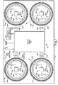
- a tire condition communication system 10 is schematically shown within an associated vehicle 12 in Fig. 1.
- the vehicle 12 has a plurality of inflatable tires (e.g., 14A).
- the vehicle 12 has four tires 14A-14D.
- the vehicle 12 may have a different number of tires.
- the vehicle 12 may include a fifth tire (not shown) that is stored as a spare tire.
- the system 10 includes a plurality of tire condition sensor units (e.g., 18A) for sensing one or more tire conditions at the vehicle tires (e.g., 14A) .
- the number of tire condition sensor units 18A-18D is equal to the number of tires 14A-14D provided within the vehicle 12.
- all of the tire condition sensor units 18A-18D have the same components. Identical components are identified with identical reference numerals, with different alphabetic suffixes. It is to be appreciated that, except as noted, all of the tire condition sensor units 18A-18D generally function in the same manner. For brevity, operation of one of the tire condition sensor units (e.g., 18A) is discussed in detail, with the understanding that the discussion is generally applicable to the other tire condition sensor units (e.g., 18B-18D).
- Each tire condition sensor unit (e.g., 18A) includes a power supply (e.g., a battery 20A) that provides electrical energy to various components within the respective sensor unit.
- the electrical energy enables the tire condition sensor unit (e.g., 18A) to energize a radio frequency antenna (e.g., 22A) to emit a radio frequency signal (e.g., 24A) that is indicative of one or more sensed conditions along with an identification to a central, vehicle-based unit 28.
- a radio frequency antenna 30 receives the condition indicative signal (e.g., 24A) from the tire condition sensor unit (e.g., 18A) and the conveyed information is processed.
- each sensor unit antenna in conjunction with the vehicle-based unit antenna 30 comprises part of a means for communication from the respective tire condition sensor unit (e.g., 18A) to the vehicle-based unit 28.
- a power supply (e.g., a vehicle battery) 34 which is operatively connected to the vehicle-based unit 28, provides electrical energy to permit performance of the processing and the like.
- the vehicle-based unit 28 utilizes the processed information to provide information to a vehicle operator (not shown) via an indicator device 38.
- the indicator device 38 may be a visual display that is located on an instrument panel of the vehicle 12. Accordingly, the vehicle operator is apprised of the sensed condition(s) at the tire (e.g., 14A).
- the sensed condition may be any condition at the tire (e.g., 14A).
- the sensed condition may be inflation pressure of the tire (e.g., 14A), temperature of the tire, motion of the tire, or even a diagnostic condition of the tire condition sensor unit (e.g., 18A) itself.
- only a single antenna 30 of the vehicle-based unit 28 receives all of the condition signals 24A-24D from the plurality of tire condition sensor units 18A-18D.
- each signal conveys an identification.
- the vehicle-based unit 28 has been taught or has learned to recognize the identifications of the tires 14A-14D associated with the vehicle 12 within which the system 10 is provided.
- the tire condition sensor unit e.g., 18A
- operates i.e., senses the condition(s) and transmits the condition signal
- the condition signal 24A i.e., the communication from the tire condition sensor unit
- may be interrupted thus leaving the vehicle-based unit 28 without current tire condition information.
- the vehicle-based unit 28 In order for the vehicle-based unit 28 to obtain current tire condition information or otherwise obtain performance from the tire condition sensor units 18A-18D, the vehicle-based unit has an ability to control operation of the tire condition sensor units and thus control the communication from the tire condition sensor units.
- the system 10 includes a plurality of antennas 40A-40D that are operatively connected 42A-42D to the vehicle-based unit 28. Each antenna (e.g., 40A) is controlled to be energized by the vehicle-based unit 28 to output a control signal (e.g., 44A) that causes an associated one (e.g., 18A) of the tire condition sensor units to perform its function.
- a control signal e.g., 44A
- the respective tire condition sensor unit (e.g., 18A) operates to sense the certain condition(s) and transmit its condition signal (e.g., 24A) in response to the control signal (e.g., 44C).
- the system 10 is configured such that so long as the control signal (e.g., 44A) is provided, the respective tire condition sensor unit (e.g., 18A) continues to operate.
- the transmission of a control signal is during, i.e., in response to, reception of a condition signal (e.g., 24A) at the vehicle-based unit 28.
- a condition signal e.g., 24A
- the associated control signal e.g., 44A
- the tire condition sensor unit e.g., 18A
- the vehicle-based unit 28 has taken control of the tire condition sensor unit (e.g., 18A).
- the output of the control signal (e.g., 44A) and thus the control of the tire condition sensor unit (e.g., 18A) by the vehicle-based unit 28 is selective.
- the vehicle-based unit 28 makes a determination as to whether the tire condition sensor unit (e.g., 18A) is to be controlled to continue to operate.
- each control signal (e.g., 44A) is a low frequency signal that is provided in the form of a magnetic field or magnetic induction signal.
- the frequency of the control signals (44A-44D) is much lower that the frequency of the condition signals (24A-24D) that convey the tire condition information to the vehicle-based unit 28.
- the frequencies of the control signals 44A-44D are each at or near 125 kHz.
- the antennas 40A-40D are magnetic field induction coils.
- the antennas 40A-40D are referred to as low frequency antennas.
- other frequencies e.g., 13 MHz
- Each low frequency antenna (e.g., 40A) is mounted on the vehicle 12 at a location adjacent to a respective one (e.g., 14A) of the vehicle tires.
- each low frequency antenna (e.g., 40A) is mounted within the wheel well associated with the respective tire (e.g., 14A).
- Signal strength of each low frequency control signal (e.g., 44A) drops considerably as the distance from the outputting low frequency antenna (e.g., 40A) increases.
- magnetic field signal strength decreases as a function of the inverse of the cube of the distance (1/D 3 ) from the antenna.
- the low frequency control signals 44A-44D are output at a strength to only permeate the space within the associated wheel well, about the associated tire.
- the low frequency control signals 44A-44D are preferably not output at a strength to noticeably permeate the space about any of the other tires (e.g., 14B-14D).
- Each tire condition sensor unit (e.g., 18A) includes a low frequency reception antenna (e.g., 48A) for receiving the control signal (e.g., 44A) that is output from the low frequency antenna (e.g., 40A) located adjacent to the respective tire (e.g., 14A) to which the tire condition sensor unit is associated.
- the low frequency reception antennas 48A-48D are magnetic induction coils.
- Each associated pair of low frequency antennas (e.g., 40A and 48A) comprise part of a means for communication from the vehicle-based unit 28 to the respective tire condition sensor unit (e.g., 18A).
- the communication from the vehicle-based unit 28 to the respective tire condition sensor unit is a control stimulus only and does not convey information, such as identification information. It is contemplated that information could be conveyed.
- the pairing of low frequency antennas (e.g., 40A and 48A) as a means for communication from the vehicle-based unit 28 to the respective tire condition sensor unit (e.g., 18A) provides sufficient ability to select and control the associated tire condition sensor unit.
- the system 10 lends itself to ease of testing the operability of the tire condition sensor units 18A-18D.
- output of a control signal (e.g., 44C) to an associated tire condition sensor unit (e.g., 18A) should cause continuing operation of the tire condition sensor unit, and thus should cause provision of the tire condition signal (e.g., 24A).
- the control signal (e.g., 44A) may be provided for any length of time to ensure sufficient opportunity for the tire condition sensor unit (e.g., 18A) to respond with its communication.
- the vehicle-based unit 28 interprets the lack of the communication from the tire condition sensor unit (e.g., 18A) as an indication that the sensor unit is faulty (e.g., dying battery).
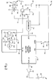
- Fig. 2 schematically illustrates one example of a tire condition sensor unit 18 (generically shown without alphabetic suffixes on the reference numerals).
- An application specific integrated circuit (ASIC) 52 is operatively connected 54 to the battery 20, via input V DD .
- the ASIC 52 includes various circuitries.
- the ASIC 52 includes circuits that provide one or more sensor devices (e.g., an inflation pressure sensor).
- the ASIC 52 also includes circuits that store an identification in a memory, assemble a message containing sensory information and the identification, and output the message as an electrical data signal.
- the ASIC 52 also includes a circuit that provides a timer.
- An amplifier 56 is operatively connected 58 to a data output of the ASIC 52 and is also operatively connected 60 to the antenna 22. In response to an electrical data signal from the ASIC 52, the amplifier 56 stimulates the antenna 22 such that the tire condition signal 24 is output.
- the timer circuit within the ASIC 52 controls the sensing and signal output in accordance with a prearranged/preprogrammed time schedule.
- the ASIC 52 has an input (identified as a sleep input) operatively connected 62 to the battery 20 through a centrifugal switch 64.
- a sleep input When the associated tire is not in motion (e.g., the vehicle is parked) the ASIC 52 is in asleep mode. Within the sleep mode, various functions are suspended (e.g., sensory information is not derived). Thus, the sleep mode helps conserve battery power.
- the low frequency reception antenna 48 includes an induction coil 66 and a capacitor 68 that are connected in parallel.
- the received control signal 44 is transformed into an electrical signal.
- the parallel connected coil 66 and capacitor 68 are connected across the inputs of an amplifier 70, which amplifies (e.g., amplitude) the electrical signal representing the received control signal.
- An output of the amplifier 70 is connected 72 to an integrator 74, which is in turn connected 76 to an input (identified as test input) of the ASIC 52.
- the ASIC 52 is controlled to operate (e.g., sense the condition(s) and output the data signal to the amplifier 56).
- the amplifier 70 is connected 80 to receive electrical energy from the battery 20 via a switch 82.
- the switch 82 is a transistor.
- a timer circuit 84 controls the switch 82.
- the timer circuit 84 is constructed and connected 86 to an output (identified as TX ON) of the ASIC 52 such that the timer circuit is energized to operate when the data signal is output to the amplifier 56 to cause condition signal transmission. Once the data signal ceases, the timer circuit 84 times-out a predetermined time duration. Thus, the powering of the amplifier 70 is via a duty cycle.
- the switch 82 is ON such that the amplifier 70 is powered.
- the control signal 44 can be received.
- the amplifier 70 is continuously energized to continue to receive the control signal.
- the reception of the control signal 44 and transmission of the condition signal 24 continues until the vehicle-based unit 28 (Fig. 1) ceases transmission of the control signal.
- the system 10 has the feature of closed loop control of the communication from the tire condition sensor units 18A-18D, with the vehicle-based unit 28 possessing the ability to control the communication.
- the timer circuit 84 and the switch 82 are thus considered an arrangement for providing power to the amplifier. It is to be realized the power providing arrangement may have any suitable construction/configuration to accomplish the task of providing power to the amplifier in a decided manner (e.g., during, and continuing after, the condition signal transmission).
- the switch 82 is a PNP type transistor, with the emitter connected 90 to the battery 20 and the collector connected 80 to the power input of the amplifier 70. The base of the PNP transistor is connected 92 to a node 94 between two serially connected resistors 96 and 98.
- the first resistor 96 has an end that is connected 102 to the battery 20, and the second resistor 98 has an end that is connected 104 to the collector of a NPN transistor 106.
- the emitter of the NPN transistor 106 is connected 108 to electrical ground.
- a resistor 110 is connected to the base of the NPN transistor 106.
- the other end of the resistor 110 is connected 114 to a node 116.
- Connected to the node 116 is an input from the ASIC that provides a current source 120.
- a capacitor 122 is connected 124 to the node 116 and is connected 126 to electrical ground. While the ASIC 52 provides current, and before the capacitor 122 discharges after cessation of the current from the ASIC, the NPN transistor 106 and PNP transistor 82 are ON and power is provided to the amplifier 70.
- the use of the amplifier 70 that has a controlled power supply can concurrently permit the use of smaller components (e.g., the antenna 48 and the antenna 40, see Fig. 1), and can thus permit reduced power consumption. Also, the duty-cycling of the provision of power to the amplifier 70 also permits reduced power consumption.
- Fig. 3 schematically illustrates one example of the vehicle-based unit 28.
- the antenna 30 is operatively connected 130 to radio frequency receive circuitry 132 at the vehicle-based unit 28.
- the reception of the condition signal results in the provision of an electrical stimulation signal to the radio frequency receive circuitry 132.
- the radio frequency receive circuitry 132 is operatively connected 134 to a controller 136 such that the contents of the received condition signal (e.g., 24A) are conveyed to the controller.
- the controller 136 processes the received information from the condition signal.
- the controller 136 compares the signal-conveyed identification to an identification provided from an identifications memory 138 that is operatively connected 140 to the controller 136. If the identification (i.e., from a tire condition sensor unit located at a tire on the vehicle) is a valid identification, the controller 136 further processes the information conveyed via the signal and provides an appropriate signal to the indicator device 38. For example, if the sensed condition is inflation pressure, the controller 136 provides control signals such that the indicator device 38 provides an indication of the sensed pressure.
- the controller 136 of the vehicle-based unit 28 is also operatively connected 142 to a low frequency selection and driver component 144.
- the low frequency selection and driver component 144 is operatively connected 42A-42D to the plurality of low frequency antennas 40A-40D.
- the controller 136 monitors one or more factors or parameters (e.g., reception of condition signals) that are used to determine whether to send a control signal (e.g., 44A) to a tire condition sensor unit (e.g., 18A, Fig. 1) and take control of the operation of that tire condition sensor unit.
- a control signal e.g., 44A
- the controller 136 provides a signal to the low frequency selection and driver component 144 to cause a stimulus signal to be provided to one of the low frequency antennas (e.g., 40A).
- the present invention permits the vehicle-based unit 28 to control the communication.
- the control provided by the vehicle-based unit 28 permits correction of errors that may occur, such as by signal collisions, merely by causing repeat signal transmissions. If interference of a signal does occur, communication can immediately be re-initialized.
- the low frequency antennas are used for conveyance of the control signal, it is contemplated that the control signal may be conveyed via different structure. Also, the control signal may convey information to the associated tire condition sensor unit.
Landscapes
- Engineering & Computer Science (AREA)
- Mechanical Engineering (AREA)
- Arrangements For Transmission Of Measured Signals (AREA)
- Measuring Fluid Pressure (AREA)
Priority Applications (1)
| Application Number | Priority Date | Filing Date | Title |
|---|---|---|---|
| EP09010352A EP2119578A3 (fr) | 2000-11-14 | 2001-11-08 | Communication de capteur d'état de pneu avec une réception latérale de pneu amplifiée et à cycle de travail |
Applications Claiming Priority (2)
| Application Number | Priority Date | Filing Date | Title |
|---|---|---|---|
| US711588 | 2000-11-14 | ||
| US09/711,588 US6667687B1 (en) | 2000-11-14 | 2000-11-14 | Tire condition sensor communication with duty-cycled, amplified tire-side reception |
Related Child Applications (2)
| Application Number | Title | Priority Date | Filing Date |
|---|---|---|---|
| EP09010352A Division-Into EP2119578A3 (fr) | 2000-11-14 | 2001-11-08 | Communication de capteur d'état de pneu avec une réception latérale de pneu amplifiée et à cycle de travail |
| EP09010352A Division EP2119578A3 (fr) | 2000-11-14 | 2001-11-08 | Communication de capteur d'état de pneu avec une réception latérale de pneu amplifiée et à cycle de travail |
Publications (4)
| Publication Number | Publication Date |
|---|---|
| EP1205317A2 true EP1205317A2 (fr) | 2002-05-15 |
| EP1205317A3 EP1205317A3 (fr) | 2003-03-19 |
| EP1205317B1 EP1205317B1 (fr) | 2009-12-23 |
| EP1205317B2 EP1205317B2 (fr) | 2015-03-11 |
Family
ID=24858679
Family Applications (2)
| Application Number | Title | Priority Date | Filing Date |
|---|---|---|---|
| EP01126688.9A Expired - Lifetime EP1205317B2 (fr) | 2000-11-14 | 2001-11-08 | Communication de capteur de condition de pneumatique avec réception avec amplification à rapport cyclique du côté du pneumatique |
| EP09010352A Withdrawn EP2119578A3 (fr) | 2000-11-14 | 2001-11-08 | Communication de capteur d'état de pneu avec une réception latérale de pneu amplifiée et à cycle de travail |
Family Applications After (1)
| Application Number | Title | Priority Date | Filing Date |
|---|---|---|---|
| EP09010352A Withdrawn EP2119578A3 (fr) | 2000-11-14 | 2001-11-08 | Communication de capteur d'état de pneu avec une réception latérale de pneu amplifiée et à cycle de travail |
Country Status (3)
| Country | Link |
|---|---|
| US (1) | US6667687B1 (fr) |
| EP (2) | EP1205317B2 (fr) |
| DE (1) | DE60140849D1 (fr) |
Cited By (6)
| Publication number | Priority date | Publication date | Assignee | Title |
|---|---|---|---|---|
| US6667687B1 (en) * | 2000-11-14 | 2003-12-23 | Trw Inc. | Tire condition sensor communication with duty-cycled, amplified tire-side reception |
| EP1419907A1 (fr) * | 2002-11-12 | 2004-05-19 | Pacific Industrial Co., Ltd. | Appareil de surveillance de condition de pneumatique |
| EP1433626A2 (fr) * | 2002-12-25 | 2004-06-30 | Pacific Industrial Co., Ltd. | Appareil de surveillance de condition de pneumatique |
| EP1452349A3 (fr) * | 2003-02-28 | 2006-03-15 | Pacific Industrial Co., Ltd. | Emetteur d'un appareil de surveillance des conditions d'un pneumatique et appareil de surveillance associé |
| EP1674299A2 (fr) * | 2004-12-22 | 2006-06-28 | Denso Corporation | Capteur de pression pneumatique avec récepteur de commande à sensibilité de réception variable |
| FR3004673A1 (fr) * | 2013-04-19 | 2014-10-24 | Continental Automotive France | Procede d'assistance pour l'ajustement de la pression d'un pneumatique equipant une roue montee sur un vehicule automobile |
Families Citing this family (29)
| Publication number | Priority date | Publication date | Assignee | Title |
|---|---|---|---|---|
| US8266465B2 (en) | 2000-07-26 | 2012-09-11 | Bridgestone Americas Tire Operation, LLC | System for conserving battery life in a battery operated device |
| US7161476B2 (en) | 2000-07-26 | 2007-01-09 | Bridgestone Firestone North American Tire, Llc | Electronic tire management system |
| US6745624B2 (en) * | 2002-02-05 | 2004-06-08 | Ford Global Technologies, Llc | Method and system for calibrating a tire pressure sensing system for an automotive vehicle |
| US6985076B1 (en) | 2002-08-07 | 2006-01-10 | Ford Global Technologies, Llc | Method and system for detecting the presence of a spare replacement in a tire pressure monitoring system for an automotive vehicle |
| US7026922B1 (en) | 2002-08-07 | 2006-04-11 | Ford Global Technologies, Llc | Method and apparatus for automatically identifying the location of pressure sensors in a tire pressure monitoring system |
| US6982636B1 (en) * | 2002-08-07 | 2006-01-03 | Ford Global Technologies, Llc | Method and system for mitigating false alarms in a tire pressure monitoring system for an automotive vehicle |
| US6952160B1 (en) * | 2002-08-07 | 2005-10-04 | Ford Global Technologies, Llc | Method and apparatus, for identifying the location of pressure sensors in a tire pressure monitoring system |
| US20040196148A1 (en) * | 2003-04-07 | 2004-10-07 | George Albuquerque | Tire management system |
| US20040196147A1 (en) * | 2003-04-07 | 2004-10-07 | George Albuquerque | Tire Management System |
| US7518495B2 (en) * | 2003-11-18 | 2009-04-14 | Lear Corporation | Universal tire pressure monitor |
| US7224269B2 (en) | 2004-12-15 | 2007-05-29 | Ford Global Technologies, Llc | Method and system for resetting tire pressure monitoring system for an automotive vehicle |
| US7369043B2 (en) | 2005-05-11 | 2008-05-06 | Ford Global Technologies, Llc | Method and apparatus for automatically identifying the location of pressure sensors in a tire pressure monitoring system |
| US7570157B2 (en) | 2005-10-24 | 2009-08-04 | Ford Global Technologies, Llc | Method and apparatus for adjusting the pressure sensor measurement range in a tire pressure monitoring system |
| US7498930B2 (en) * | 2005-11-04 | 2009-03-03 | Delphi Technologies, Inc. | Communications interface module for vehicle |
| US7705717B2 (en) * | 2005-11-30 | 2010-04-27 | Ford Global Technologies | Method and apparatus for receiving signals from a sensor into a tire pressure monitoring system |
| EP2018281A4 (fr) * | 2006-05-17 | 2011-03-23 | Trw Automotive Us Llc | Procédé et appareil de détermination de localisation de position de pneumatique identifiable dans un système de surveillance de pression de pneumatique |
| DE102007007136B3 (de) * | 2007-02-09 | 2008-08-28 | Siemens Ag | Radelektronik und Verfahren zum Betreiben einer Radelektronik |
| US7741964B2 (en) * | 2007-05-31 | 2010-06-22 | Schrader Electronics Ltd. | Tire pressure detector having reduced power consumption mechanism |
| JP5502729B2 (ja) | 2007-07-03 | 2014-05-28 | コンティネンタル オートモーティブ システムズ ユーエス, インコーポレイティッド | 汎用タイヤ圧監視センサ |
| JP2009216465A (ja) * | 2008-03-07 | 2009-09-24 | Denso Corp | タイヤ空気圧監視システム |
| US8751092B2 (en) | 2011-01-13 | 2014-06-10 | Continental Automotive Systems, Inc. | Protocol protection |
| US8742914B2 (en) | 2011-08-09 | 2014-06-03 | Continental Automotive Systems, Inc. | Tire pressure monitoring apparatus and method |
| US9676238B2 (en) | 2011-08-09 | 2017-06-13 | Continental Automotive Systems, Inc. | Tire pressure monitor system apparatus and method |
| US8502655B2 (en) | 2011-08-09 | 2013-08-06 | Continental Automotive Systems, Inc. | Protocol misinterpretation avoidance apparatus and method for a tire pressure monitoring system |
| CN103874592B (zh) | 2011-08-09 | 2018-01-30 | 大陆汽车系统公司 | 用于激活轮胎压力监控器的定位过程的设备和方法 |
| US8576060B2 (en) | 2011-08-09 | 2013-11-05 | Continental Automotive Systems, Inc. | Protocol arrangement in a tire pressure monitoring system |
| US9446636B2 (en) | 2014-02-26 | 2016-09-20 | Continental Automotive Systems, Inc. | Pressure check tool and method of operating the same |
| US9517664B2 (en) | 2015-02-20 | 2016-12-13 | Continental Automotive Systems, Inc. | RF transmission method and apparatus in a tire pressure monitoring system |
| DE102016213290A1 (de) | 2015-08-03 | 2017-02-09 | Continental Automotive Systems, Inc. | Vorrichtung, System und Verfahren zum Konfigurieren eines Reifeninformationssensors mit einem Übertragungsprotokoll auf der Basis von Fahrzeugtriggerkenngrößen |
Citations (4)
| Publication number | Priority date | Publication date | Assignee | Title |
|---|---|---|---|---|
| US4308520A (en) † | 1976-07-30 | 1981-12-29 | Edcliff Instruments | Tire pressure indicator |
| EP0626911B1 (fr) † | 1992-02-26 | 1995-11-15 | Uwatec Ag | Dispositif de controle de la pression de gonflage de roues de vehicules equipees de pneus |
| US5880363A (en) * | 1996-08-09 | 1999-03-09 | Temic Telefunken Microelectronic Gmbh | Process for checking air pressure in vehicle wheel tires |
| US5987980A (en) * | 1995-02-23 | 1999-11-23 | Mangafas; Nicholas | In situ tire valve assembly employing short valve element as antenna |
Family Cites Families (13)
| Publication number | Priority date | Publication date | Assignee | Title |
|---|---|---|---|---|
| US4761644A (en) | 1985-06-03 | 1988-08-02 | Aisin Seiki Kabushikikaisha | Data transmission system |
| US5196845A (en) | 1988-10-24 | 1993-03-23 | Compagnie Generale Des Etablissements Michelin | Antenna for tire monitoring device |
| US6087930A (en) * | 1994-02-22 | 2000-07-11 | Computer Methods Corporation | Active integrated circuit transponder and sensor apparatus for transmitting vehicle tire parameter data |
| US5463374A (en) | 1994-03-10 | 1995-10-31 | Delco Electronics Corporation | Method and apparatus for tire pressure monitoring and for shared keyless entry control |
| US5500065A (en) | 1994-06-03 | 1996-03-19 | Bridgestone/Firestone, Inc. | Method for embedding a monitoring device within a tire during manufacture |
| DE69529456T2 (de) | 1994-11-14 | 2003-11-27 | Yokohama Rubber Co Ltd | Reifendrucküberwachungsvorrichtung für ein fahrzeug |
| US5612671A (en) | 1995-12-11 | 1997-03-18 | Delco Electronics Corp. | Method of learning tire pressure transmitter ID |
| US6710708B2 (en) | 1999-02-05 | 2004-03-23 | Schrader-Bridgeport International, Inc. | Method and apparatus for a remote tire pressure monitoring system |
| US7015801B1 (en) * | 2000-10-13 | 2006-03-21 | Trw Inc. | Vehicle-controlled tire condition sensor communication utilizing fixed tire identification |
| US6667687B1 (en) * | 2000-11-14 | 2003-12-23 | Trw Inc. | Tire condition sensor communication with duty-cycled, amplified tire-side reception |
| US6441728B1 (en) * | 2001-01-02 | 2002-08-27 | Trw Inc. | Tire condition sensor communication with tire location provided via vehicle-mounted identification units |
| US6414592B1 (en) | 2001-01-02 | 2002-07-02 | Trw Inc. | Tire condition sensor communication with tire location provided via manually inputted update |
| US6498967B1 (en) * | 2001-09-10 | 2002-12-24 | The Goodyear Tire & Rubber Company | Tire initiated vehicle control system |
-
2000
- 2000-11-14 US US09/711,588 patent/US6667687B1/en not_active Expired - Lifetime
-
2001
- 2001-11-08 EP EP01126688.9A patent/EP1205317B2/fr not_active Expired - Lifetime
- 2001-11-08 DE DE60140849T patent/DE60140849D1/de not_active Expired - Lifetime
- 2001-11-08 EP EP09010352A patent/EP2119578A3/fr not_active Withdrawn
Patent Citations (4)
| Publication number | Priority date | Publication date | Assignee | Title |
|---|---|---|---|---|
| US4308520A (en) † | 1976-07-30 | 1981-12-29 | Edcliff Instruments | Tire pressure indicator |
| EP0626911B1 (fr) † | 1992-02-26 | 1995-11-15 | Uwatec Ag | Dispositif de controle de la pression de gonflage de roues de vehicules equipees de pneus |
| US5987980A (en) * | 1995-02-23 | 1999-11-23 | Mangafas; Nicholas | In situ tire valve assembly employing short valve element as antenna |
| US5880363A (en) * | 1996-08-09 | 1999-03-09 | Temic Telefunken Microelectronic Gmbh | Process for checking air pressure in vehicle wheel tires |
Cited By (10)
| Publication number | Priority date | Publication date | Assignee | Title |
|---|---|---|---|---|
| US6667687B1 (en) * | 2000-11-14 | 2003-12-23 | Trw Inc. | Tire condition sensor communication with duty-cycled, amplified tire-side reception |
| EP1419907A1 (fr) * | 2002-11-12 | 2004-05-19 | Pacific Industrial Co., Ltd. | Appareil de surveillance de condition de pneumatique |
| US6967571B2 (en) | 2002-11-12 | 2005-11-22 | Pacific Industrial Co., Ltd. | Tire condition monitoring apparatus |
| EP1433626A2 (fr) * | 2002-12-25 | 2004-06-30 | Pacific Industrial Co., Ltd. | Appareil de surveillance de condition de pneumatique |
| EP1433626A3 (fr) * | 2002-12-25 | 2006-01-25 | Pacific Industrial Co., Ltd. | Appareil de surveillance de condition de pneumatique |
| EP1452349A3 (fr) * | 2003-02-28 | 2006-03-15 | Pacific Industrial Co., Ltd. | Emetteur d'un appareil de surveillance des conditions d'un pneumatique et appareil de surveillance associé |
| EP1674299A2 (fr) * | 2004-12-22 | 2006-06-28 | Denso Corporation | Capteur de pression pneumatique avec récepteur de commande à sensibilité de réception variable |
| EP1674299A3 (fr) * | 2004-12-22 | 2007-02-14 | Denso Corporation | Capteur de pression pneumatique avec récepteur de commande à sensibilité de réception variable |
| US7315240B2 (en) | 2004-12-22 | 2008-01-01 | Denso Corporation | Tire inflation pressure sensing apparatus with command signal receiver having variable receiver sensitivity |
| FR3004673A1 (fr) * | 2013-04-19 | 2014-10-24 | Continental Automotive France | Procede d'assistance pour l'ajustement de la pression d'un pneumatique equipant une roue montee sur un vehicule automobile |
Also Published As
| Publication number | Publication date |
|---|---|
| EP2119578A3 (fr) | 2010-02-17 |
| EP1205317B2 (fr) | 2015-03-11 |
| DE60140849D1 (de) | 2010-02-04 |
| EP2119578A2 (fr) | 2009-11-18 |
| US6667687B1 (en) | 2003-12-23 |
| EP1205317B1 (fr) | 2009-12-23 |
| EP1205317A3 (fr) | 2003-03-19 |
Similar Documents
| Publication | Publication Date | Title |
|---|---|---|
| EP1205317B2 (fr) | Communication de capteur de condition de pneumatique avec réception avec amplification à rapport cyclique du côté du pneumatique | |
| US7015801B1 (en) | Vehicle-controlled tire condition sensor communication utilizing fixed tire identification | |
| US20030145650A1 (en) | Tire pressure monitoring system with pressure gauge operating mode for indicating when air pressure within a tire is within a predetermined pressure range | |
| US7202777B2 (en) | Tire condition monitoring system | |
| US6441728B1 (en) | Tire condition sensor communication with tire location provided via vehicle-mounted identification units | |
| KR100985316B1 (ko) | 휠 식별 장치 및 휠 식별 기능을 갖춘 타이어 공기압 검출장치 | |
| US6604416B2 (en) | Tire monitoring transmitter with various operation modes | |
| US6501372B2 (en) | Tire condition sensor communication with unique sampling on vehicle-side diversity antenna array | |
| KR100839165B1 (ko) | 차량 휠 정보 처리장치 및 그 방법 | |
| EP1829713B1 (fr) | Appareil de détection de la pression de gonflage de pneus doté d'une fonction pour identifier les roues de roulement et de secours | |
| CN101391563B (zh) | 轮胎充气压力检测装置 | |
| CN109720156B (zh) | 轮胎传感器定位方法和装置 | |
| US20020003474A1 (en) | Method and apparatus for a remote tire pressure monitoring system | |
| US20080143507A1 (en) | Tire pressure monitoring system for associating tire pressure monitoring sensors with wheel locations on a vehicle | |
| JP3632561B2 (ja) | 空気圧検出装置及びタイヤ状態監視システム | |
| US7854163B2 (en) | Wheel identifying apparatus and tire inflation pressure detecting apparatus with function of wheel identification | |
| US7154414B2 (en) | System and method for remote tire pressure monitoring | |
| WO2006074203A2 (fr) | Systeme et procede pour faciliter l'identification de l'emplacement d'un module a distance | |
| US20050258951A1 (en) | Tire parameter sensing system having auto-location feature and associated method | |
| US20090184814A1 (en) | Wireless tire pressure monitoring system with interactive multiple frequency channel | |
| US8026803B2 (en) | Apparatus and process for monitoring a vehicle condition | |
| EP1270276B1 (fr) | Appareil de surveillance de condition de pneumatique | |
| JP4123979B2 (ja) | タイヤ空気圧監視システム | |
| JP4192789B2 (ja) | 車両のタイヤ状態監視システム | |
| EP1384605B1 (fr) | Appareil de surveillance de condition de pneumatique |
Legal Events
| Date | Code | Title | Description |
|---|---|---|---|
| PUAI | Public reference made under article 153(3) epc to a published international application that has entered the european phase |
Free format text: ORIGINAL CODE: 0009012 |
|
| AK | Designated contracting states |
Kind code of ref document: A2 Designated state(s): AT BE CH CY DE DK ES FI FR GB GR IE IT LI LU MC NL PT SE TR |
|
| AX | Request for extension of the european patent |
Free format text: AL;LT;LV;MK;RO;SI |
|
| PUAL | Search report despatched |
Free format text: ORIGINAL CODE: 0009013 |
|
| AK | Designated contracting states |
Kind code of ref document: A3 Designated state(s): AT BE CH CY DE DK ES FI FR GB GR IE IT LI LU MC NL PT SE TR |
|
| AX | Request for extension of the european patent |
Extension state: AL LT LV MK RO SI |
|
| 17P | Request for examination filed |
Effective date: 20030919 |
|
| AKX | Designation fees paid |
Designated state(s): DE FR GB |
|
| RAP1 | Party data changed (applicant data changed or rights of an application transferred) |
Owner name: TRW AUTOMOTIVE U.S. LLC |
|
| GRAP | Despatch of communication of intention to grant a patent |
Free format text: ORIGINAL CODE: EPIDOSNIGR1 |
|
| GRAS | Grant fee paid |
Free format text: ORIGINAL CODE: EPIDOSNIGR3 |
|
| GRAA | (expected) grant |
Free format text: ORIGINAL CODE: 0009210 |
|
| AK | Designated contracting states |
Kind code of ref document: B1 Designated state(s): DE FR GB |
|
| REG | Reference to a national code |
Ref country code: GB Ref legal event code: FG4D |
|
| REF | Corresponds to: |
Ref document number: 60140849 Country of ref document: DE Date of ref document: 20100204 Kind code of ref document: P |
|
| PLBI | Opposition filed |
Free format text: ORIGINAL CODE: 0009260 |
|
| PLAX | Notice of opposition and request to file observation + time limit sent |
Free format text: ORIGINAL CODE: EPIDOSNOBS2 |
|
| 26 | Opposition filed |
Opponent name: BORGWARNER BERU SYSTEMS GMBH Effective date: 20100922 |
|
| PLAF | Information modified related to communication of a notice of opposition and request to file observations + time limit |
Free format text: ORIGINAL CODE: EPIDOSCOBS2 |
|
| PGFP | Annual fee paid to national office [announced via postgrant information from national office to epo] |
Ref country code: GB Payment date: 20101124 Year of fee payment: 10 |
|
| PLBB | Reply of patent proprietor to notice(s) of opposition received |
Free format text: ORIGINAL CODE: EPIDOSNOBS3 |
|
| PGFP | Annual fee paid to national office [announced via postgrant information from national office to epo] |
Ref country code: FR Payment date: 20111128 Year of fee payment: 11 |
|
| GBPC | Gb: european patent ceased through non-payment of renewal fee |
Effective date: 20121108 |
|
| REG | Reference to a national code |
Ref country code: FR Ref legal event code: ST Effective date: 20130731 |
|
| PG25 | Lapsed in a contracting state [announced via postgrant information from national office to epo] |
Ref country code: FR Free format text: LAPSE BECAUSE OF NON-PAYMENT OF DUE FEES Effective date: 20121130 Ref country code: GB Free format text: LAPSE BECAUSE OF NON-PAYMENT OF DUE FEES Effective date: 20121108 |
|
| APBM | Appeal reference recorded |
Free format text: ORIGINAL CODE: EPIDOSNREFNO |
|
| APBP | Date of receipt of notice of appeal recorded |
Free format text: ORIGINAL CODE: EPIDOSNNOA2O |
|
| APAH | Appeal reference modified |
Free format text: ORIGINAL CODE: EPIDOSCREFNO |
|
| APBU | Appeal procedure closed |
Free format text: ORIGINAL CODE: EPIDOSNNOA9O |
|
| PUAH | Patent maintained in amended form |
Free format text: ORIGINAL CODE: 0009272 |
|
| STAA | Information on the status of an ep patent application or granted ep patent |
Free format text: STATUS: PATENT MAINTAINED AS AMENDED |
|
| 27A | Patent maintained in amended form |
Effective date: 20150311 |
|
| AK | Designated contracting states |
Kind code of ref document: B2 Designated state(s): DE FR GB |
|
| REG | Reference to a national code |
Ref country code: DE Ref legal event code: R102 Ref document number: 60140849 Country of ref document: DE |
|
| REG | Reference to a national code |
Ref country code: DE Ref legal event code: R102 Ref document number: 60140849 Country of ref document: DE Effective date: 20150311 |
|
| REG | Reference to a national code |
Ref country code: DE Ref legal event code: R082 Ref document number: 60140849 Country of ref document: DE Representative=s name: PRINZ & PARTNER MBB PATENTANWAELTE RECHTSANWAE, DE |
|
| PGFP | Annual fee paid to national office [announced via postgrant information from national office to epo] |
Ref country code: DE Payment date: 20181128 Year of fee payment: 18 |
|
| REG | Reference to a national code |
Ref country code: DE Ref legal event code: R082 Ref document number: 60140849 Country of ref document: DE Representative=s name: PRINZ & PARTNER MBB PATENTANWAELTE RECHTSANWAE, DE Ref country code: DE Ref legal event code: R081 Ref document number: 60140849 Country of ref document: DE Owner name: BCS AUTOMOTIVE INTERFACE SOLUTIONS US LLC, WIL, US Free format text: FORMER OWNER: TRW AUTOMOTIVE U.S. LLC, LIVONIA, MICH., US |
|
| REG | Reference to a national code |
Ref country code: DE Ref legal event code: R119 Ref document number: 60140849 Country of ref document: DE |
|
| PG25 | Lapsed in a contracting state [announced via postgrant information from national office to epo] |
Ref country code: DE Free format text: LAPSE BECAUSE OF NON-PAYMENT OF DUE FEES Effective date: 20200603 |