US6982636B1 - Method and system for mitigating false alarms in a tire pressure monitoring system for an automotive vehicle - Google Patents
Method and system for mitigating false alarms in a tire pressure monitoring system for an automotive vehicle Download PDFInfo
- Publication number
- US6982636B1 US6982636B1 US10/064,688 US6468802A US6982636B1 US 6982636 B1 US6982636 B1 US 6982636B1 US 6468802 A US6468802 A US 6468802A US 6982636 B1 US6982636 B1 US 6982636B1
- Authority
- US
- United States
- Prior art keywords
- pressure
- status
- signal
- warning
- status signal
- Prior art date
- Legal status (The legal status is an assumption and is not a legal conclusion. Google has not performed a legal analysis and makes no representation as to the accuracy of the status listed.)
- Expired - Lifetime
Links
Images


Classifications
-
- B—PERFORMING OPERATIONS; TRANSPORTING
- B60—VEHICLES IN GENERAL
- B60C—VEHICLE TYRES; TYRE INFLATION; TYRE CHANGING; CONNECTING VALVES TO INFLATABLE ELASTIC BODIES IN GENERAL; DEVICES OR ARRANGEMENTS RELATED TO TYRES
- B60C23/00—Devices for measuring, signalling, controlling, or distributing tyre pressure or temperature, specially adapted for mounting on vehicles; Arrangement of tyre inflating devices on vehicles, e.g. of pumps or of tanks; Tyre cooling arrangements
- B60C23/02—Signalling devices actuated by tyre pressure
- B60C23/04—Signalling devices actuated by tyre pressure mounted on the wheel or tyre
- B60C23/0408—Signalling devices actuated by tyre pressure mounted on the wheel or tyre transmitting the signals by non-mechanical means from the wheel or tyre to a vehicle body mounted receiver
Definitions
- the present invention is related to applications Ser. No. 10/064,693 entitled a “Method And System For Resetting Tire Pressure Monitoring System For An Automotive Vehicle”; Ser. No. 10/064,694 entitled “Method And System For Detecting The Presence Of A Spare Replacement In A Tire Pressure Monitoring System For An Automotive Vehicle”; Ser. No. 10/064,695 entitled “Method And System For Automatically Extending A Tire Pressure Monitoring System For An Automotive Vehicle To Include Auxiliary Tires”; Ser. No. 10/064,687 entitled “Method And System Of Notifying Of Overuse Of A Mini-Spare Tire In A Tire Pressure Monitoring System For An Automotive Vehicle”; Ser. No.
- 10/064,690 entitled “Method And Apparatus For Identifying The Location Of Pressure Sensors In A Tire Pressure Monitoring System”; Ser. No. 10/064,692 entitled “Tire Pressure Monitoring System With A Signal Initiator”; Ser. No. 10/064,691 entitled “Method And Apparatus For Automatically Identifying The Location Of Pressure Sensors In A Tire Pressure Monitoring System”; Ser. No. 10/065,468 entitled “Method And Apparatus For Reminding The Vehicle Operator To Refill The Spare Tire In A Tire Pressure Monitoring System”; filed simultaneously herewith and incorporated by reference herein.
- the present invention relates generally to a system for monitoring tire pressures in an automotive vehicle, and more particularly, to a method and system for monitoring the tire pressure system and prevent false warnings.
- Various types of pressure sensing systems for monitoring the pressure within the tires of an automotive vehicle have been proposed. Such systems generate a pressure signal using an electromagnetic (EM) signal, which is transmitted to a receiver. The pressure signal corresponds to the pressure within the tire. When the tire pressure drops below a predetermined pressure, an indicator is used to signal the vehicle operator of the low pressure.
- EM electromagnetic
- Known systems include coupling a pressure sensor to the valve stem of the tire.
- Other known systems and proposed systems locate the pressure sensors in various locations within the tire wall or tread.
- Tires are mounted to wheels that are commonly made from steel or aluminum.
- Signals from the pressure sensors are read by the system and a low pressure warning is generated when the pressure is below a predetermined threshold.
- a predetermined threshold may not distinguish flat tires and high pressure situations.
- a delay may be formed in such systems upon activation or reactivation of the system. Such delays are not desired in tire pressure monitoring systems because on start up of the system if a low tire pressure is present, it would be desirable to provide the driver with instant notification thereof.
- the present invention provides a system and method for generating timely warnings to a vehicle operator as to the pressure of the tires.
- the present invention provides a two-stage determination. In the first stage, a sensor pressure status is obtained. In the second stage, the sensor pressure status is qualified and a warning status is generated.
- a pressure monitoring system for a tire of an automotive vehicle includes a first pressure sensor coupled to the wheel, a transmitter coupled to the pressure sensor whereby the transmitter generates a pressure signal.
- a controller is coupled to the transmitter. The controller receives the pressure signal and in a first stage, compares the pressure signal to a pressure threshold to obtain a sensor status. In a second stage, the controller qualifies the sensor status signal by generating a warning status in response to the sensor status.
- a method of operating a pressure monitoring system comprises: transmitting a plurality of pressure signals from a tire pressure sensor, receiving said plurality of sequential pressure signals in a controller, in a first stage, comparing the plurality of pressure signals to a pressure threshold to obtain a plurality of pressure status signals, in a second stage, determining a warning status signal in response to said plurality of pressure status signals.
- One advantage of the invention is that the system will quickly respond in a start up mode when a warning is detected to reduce the time associated with the warning to allow early remediation.
- FIG. 1 is a block diagrammatic view of a pressure monitoring system according to the present invention.
- FIG. 2 is a functional flowchart of the monitoring system according to the present invention.
- FIG. 3 is a block diagrammatic view of a pressure transmitter according to the present invention.
- FIG. 4 is a diagrammatic view of a digital word from a pressure transmitter.
- FIG. 5 is a flow chart illustrating determining a pressure status in a first stage of pressure determination according to the present invention.
- FIG. 6 is a flow chart illustrating determining a warning status in a second stage of pressure determination according to the present invention.
- FIG. 7 is a state diagram of low pressure sensor status according to the present invention.
- FIG. 8 is a state diagram of high pressure sensor status according to the present invention.
- FIG. 9 is a state diagram of a flat pressure sensor status.
- FIG. 10 is a table summarizing the results obtained from the state diagrams illustrated in FIGS. 7 , 8 and 9 .
- FIG. 11 is a state diagram of a low pressure warning status.
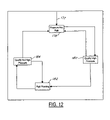
- FIG. 12 is a state diagram of a high pressure warning status.
- FIG. 13 is a state diagram of a flat pressure warning status.
- an automotive vehicle 10 has a pressure monitoring system 12 for monitoring the air pressure within a left front tire 14 a , a right front tire 14 b , a right rear tire 14 c , and a left rear tire 14 d .
- Each tire 14 a – 14 d has a respective tire pressure sensor circuit 16 a , 16 b , 16 c , and 16 d , each of which has a respective antenna 18 a , 18 b , 18 c , and 18 d .
- Each tire is positioned upon a corresponding wheel.
- a fifth tire or spare tire 14 e is also illustrated having a tire pressure sensor circuit 16 e and a respective antenna 18 e .
- five wheels are illustrated, the pressure of various numbers of wheels may be increased.
- the present invention applies equally to vehicles such as pickup trucks that have dual wheels for each rear wheel.
- various numbers of wheels may be used in a heavy duty truck application having dual wheels at a number of locations.
- the present invention is also applicable to trailers and extra spares as will be further described below.
- Each tire 14 may have a respective initiator 20 a – 20 e positioned within the wheel wells adjacent to the tire 14 .
- Initiator 20 generates a low frequency RF signal initiator and is used to initiate a response from each wheel so that the position of each wheel may be recognized automatically by the pressure monitoring system 12 .
- Initiators 20 a – 20 e are preferably coupled directly to a controller 22 . In commercial embodiments where the position programming is done manually, the initiators may be eliminated.
- Controller 22 is preferably a microprocessor based controller having a programmable CPU that may be programmed to perform various functions and processes including those set forth herein.
- Controller 22 has a memory 26 associated therewith.
- Memory 26 may be various types of memory including ROM or RAM. Memory 26 is illustrated as a separate component. However, those skilled in the art will recognize controller 22 may have memory 26 therein.
- Memory 26 is used to store various thresholds, calibrations, tire characteristics, wheel characteristics, serial numbers, conversion factors, temperature probes, spare tire operating parameters, and other values needed in the calculation, calibration and operation of the pressure monitoring system 12 .
- memory may contain a table that includes the sensor identification thereof. Also, the warning statuses of each of the tires may also be stored within the table.
- Controller 22 is also coupled to a receiver 28 .
- receiver 28 is illustrated as a separate component, receiver 28 may also be included within controller 22 .
- Receiver 28 has an antenna 30 associated therewith.
- Receiver 30 is used to receive pressure and various information from tire pressure circuits 16 a – 16 e .
- Controller 22 is also coupled to a plurality of sensors. Such sensors may include a barometric pressure sensor 32 , an ambient temperature sensor 34 , a distance sensor 36 , a speed sensor 38 , a brake pedal sensor 40 , and an ignition sensor 42 . Of course, various other types of sensors may be used.
- Barometric pressure sensor 32 generates a barometric pressure signal corresponding to the ambient barometric pressure.
- the barometric pressure may be measured directly, calculated, or inferred from various sensor outputs.
- the barometric pressure compensation is preferably used but is not required in calculation for determining the pressure within each tire 14 .
- Temperature sensor 34 generates an ambient temperature signal corresponding to the ambient temperature and may be used to generate a temperature profile.
- Distance sensor 36 may be one of a variety of sensors or combinations of sensors to determine the distance traveled for the automotive vehicle. The distance traveled may merely be obtained from another vehicle system either directly or by monitoring the velocity together with a timer 44 to obtain a rough idea of distance traveled.
- Speed sensor 38 may be a variety of speed sensing sources commonly used in automotive vehicles such as a two wheel used in anti-lock braking systems, or a transmission sensor.
- Timer 44 may also be used to measure various times associated with the process set forth herein.
- the timer 44 may measure the time the spare tire is stowed, or measure a time after an initiator signal.
- Brake pedal sensor 41 may generate a brake-on or brake-off signal indicating that the brake pedal is being depressed or not depressed, respectively. Brake pedal sensor 41 may be useful in various applications such as the programming or calibrating of the pressure monitoring system 12 .
- Ignition sensor 42 may be one of a variety of types of sensors to determine if the ignition is powered on. When the ignition is on, a run signal may be generated. When the ignition is off, an off signal is generated. A simple ignition switch may act as an ignition sensor 42 . Of course, sensing the voltage on a particular control line may also provide an indication of whether the ignition is activated. Preferably, pressure monitoring system 12 may not be powered when the ignition is off. However, in one constructed embodiment, the system receives information about once an hour after the ignition has been turned off.
- a telemetric system 46 may be used to communicate various information to and from a central location from a vehicle.
- the control location may keep track of service intervals and use and inform the vehicle operator service is required.
- a counter 48 may also be included in control system 12 .
- Counter 48 may count, for example, the number of times a particular action is performed.
- counter 48 may be used to count the number of key-off to key-on transitions.
- the counting function may be inherent in controller 22 .
- Controller 22 may also be coupled to a button 50 or plurality of buttons 50 for inputting various information, resetting the controller 22 , or various other functions as will be evident to those skilled in the art through the following description.
- Controller 22 may also be coupled to an indicator 52 .
- Indicator 52 may include an indicator light or display panel 54 , which generates a visual signal, or an audible device 56 such as a speaker or buzzer that generates an audible signal.
- Indicator 52 may provide some indication as to the operability of the system such as confirming receipt of a signal such as a calibration signal or other commands, warnings, and controls as will be further described below.
- Indicator may be an LED or LCD panel used to provide commands to the vehicle operator when manual calibrations are performed.
- a pressure monitoring system 12 having various functional blocks is illustrated. These functional blocks may take place within receiver 28 , controller 22 , or a combination thereof. Also, memory 26 is used to store the various ranges. An end-of-line (EOL) tester 58 may also be coupled to pressure monitoring system. EOL tester 58 provides test functions to EOL diagnostic block 60 . EOL tester 58 in conjunction with EOL diagnostic block 60 may be used to provide acceptable pressure ranges 62 and other diagnostic functions to determine fault within the system. The EOL tester 58 may be used in the manufacturing process to store various information in the memory such as various thresholds, tire characteristics, and to initially program the locations corresponding to the vehicle tires.
- EOL end-of-line
- Vehicle speed sensor 38 , ignition switch 42 , and brake on/off switch 41 may be coupled to a manual learn mode activation input process block 64 .
- block 64 and sensors 38 , 41 , and 42 allow an association block 66 to associate the various tire pressure sensors to the locations of the vehicles.
- Block 66 associates the various tire pressure sensors in the memory at block 68 .
- the transmissions from the various sensors are decoded in block 70 , which may be performed in receiver 28 above.
- the decoded information is provided to block 66 and to a block 72 , which processes the various information such as the ranges, the various sensor locations, and the current transmission process.
- the sensor status pressure and transmission ID may be linked to a tire pressure monitor 74 which may be used to provide a warning status to an output block 76 which in turn may provide information to an external controller 78 and to indicator 52 .
- An auto learn block 80 may also be used to associate the various tire pressure sensor monitors with the locations of the tires in the vehicle. This process may replace or be in addition to the manual learn block 64 .
- the auto learn function uses initiators such as the initiator 20 b as shown. The various features of FIG. 2 will be described further in more detail.
- Pressure monitoring system 12 has a transmitter/receiver or transceiver 90 .
- Transmitter/receiver 90 is coupled to antenna 18 a for transmitting various information to receiver 28 .
- the receiver portion may be used to receive an activation signal for an initiator located at each wheel.
- the pressure sensor may have various information such as a serial number memory 92 , a pressure sensor 94 for determining the pressure within the tire, a temperature sensor 96 for determining the temperature within the tire, and a motion detector 98 which may be used to activate the system pressure sensing system.
- the initial message is referred to as a “wake” message, meaning the pressure sensing circuit is now activated to send its pressure transmissions and the other data.
- Battery 100 is preferably a long-life battery capable of lasting through the life of the tire.
- a sensor function monitor 101 may also be incorporated into tire pressure sensor circuit 16 .
- Sensor function monitor 101 generates an error signal when various portions of the tire pressure circuit are not operating or are operating incorrectly. Also, sensor function monitor may generate a signal indicating that the circuit 16 is operating normally.
- Word 102 may comprise a transmitter identification serial number portion 104 followed by a data portion 106 in a predetermined format.
- data section 106 may include a wake or initial status pressure information followed by temperature information.
- Motion detector 28 may initiate the transmission of the word 102 to the transmitter/receiver 90 .
- the word 102 is preferably such that the decode RF transmission block 70 is able to decode the information and validate the word while providing the identification number or serial number, the pressure, the temperature, and a sensor function.
- FIG. 5 a high level flow chart illustrating obtaining a sensor pressure status from the measured pressure is illustrated.
- the pressure status is determined in a similar manner for each of the tires on the vehicle.
- the pressure is measured at the pressure sensor and transmitted to the receiver and is ultimately used in the controller.
- the pressure measured is compared to a low pressure threshold and a low pressure warning is generated if the measured pressure is below the low pressure threshold.
- a high pressure warning is generated.
- block 126 if the measured pressure is below a flat pressure, then a flat pressure warning is generated.
- the pressure status is obtained from blocks 122 , 124 , and 126 .
- the sensor pressure status is a first stage of pressure monitoring according to the present invention.
- a second stage of pressure monitoring is illustrated in a high level flow chart view.
- a low pressure warning status, a high pressure warning status, a flat pressure warning status, and an overall sensor status is used to form a composite warning status.
- the low pressure warning status is determined.
- the high pressure warning status is determined.
- a flat pressure warning status is determined.
- preferably several measurements take place during normal operation to confirm the status.
- Each of the low pressure warning status, high pressure warning status, and flat pressure warning status are combined together to form the composite warning status in block 136 .
- the low pressure warning status, the high pressure warning status, and the flat pressure warning status may have two statuses indicative of a warning state indicating the conditions are not met and a not warning state indicating the conditions are not met.
- Block 138 corresponds to a not low sensor status.
- both the front tire pressure and the rear tire pressure may have different threshold values.
- the spare tire may also have its own threshold values.
- block 140 is performed.
- the low warning status is determined in the second stage as will be described below.
- Block 140 when the warning status is not low and the sensor is equal to or above the threshold for the tire, then the sensor pressure status is not low and the system returns to block 138 .
- block 140 when a low warning status is determined, then block 142 is performed.
- block 142 when the pressure is greater than or equal to the threshold pressure of the associated tire, then block 144 is performed.
- a “not low” warning status is determined as will be further described below.
- block 142 is executed.
- block 138 when a warning status of not low is determined, block 138 is executed.
- Blocks 138 through 144 illustrate a continuous loop in which the sensor readings are monitored and a sensor pressure status and warning status are used to move therethrough.
- FIG. 8 a similar state diagram to that of FIG. 7 is illustrated relative to a high pressure threshold.
- the warning status is not high.
- the pressure of the particular tire exceeds a high pressure threshold.
- block 148 determines a high warning status.
- a high warning status is determined as will be further described below.
- block 146 is again executed.
- block 148 if the high warning status criteria are met, a high warning status is generated and block 150 is executed.
- the thresholds may be offset slightly to provide hysteresis.
- block 150 when the pressure reading drops below a high pressure threshold then block 144 is executed. If subsequent readings are greater than the high pressure threshold then block 150 is again executed. In block 152 when the not high warning status criteria are met, as will be further described below, a not high warning status is generated and block 146 is again executed.
- FIG. 9 a state diagram for determining the presence of a flat tire is illustrated.
- block 156 is executed. Again, the thresholds may be offset slightly to provide hysteresis.
- block 56 if a subsequent pressure reading is greater than the flat threshold, then block 154 is again executed.
- block 156 if the criteria for generating a flat warning status is met, as will be further described below, block 158 is executed.
- block 158 when the pressure reading of a subsequent reading exceeds or is equal to a flat threshold, then block 160 is executed.
- Block 160 determines a not flat warning status in a similar manner to that of block 156 .
- block 160 if the subsequent readings drop below the flat warning threshold, then block 158 is again executed.
- block 160 if the criteria for not flat warning status is met, then block 154 is executed.
- FIGS. 7 , 8 , and 9 are simultaneously performed for each wheel.
- FIG. 10 the results obtained from FIGS. 7 , 8 , and 9 are shown in respective columns. True in the columns refers to that pressure threshold being crossed. Thus, the output pressure status shown in the right hand column is “in range” when each of the pressure thresholds are not met. A flat pressure status refers to the flat pressure threshold being met. A low pressure status is obtained when a low pressure threshold is crossed, and a high pressure status when a high pressure threshold is exceeded.
- blocks 140 and 144 of FIG. 7 are illustrated in further detail.
- the qualification process for either a pressure not low warning status or a low pressure warning status is illustrated.
- the system Upon an initial status reading the system is set to a false low warning status as indicated by arrow 163 and block 162 is executed.
- block 164 On the initial status reading, if a low pressure status is obtained in the first reading, block 164 is executed which immediately generates a low warning status. Thus, no waiting periods or other measurements are necessary from an initial standpoint.
- Loop 165 back to the pressure not low block 162 signifies that the initial value was in range and the status value is not an initial value.
- a warning qualification process is started in block 168 .
- block 162 is executed.
- block 168 if a predetermined number of pressure status signals are low or a certain number of pressure status signals over a fixed time period are low, for example five warning events, block 164 is executed.
- block 164 when a not low pressure status is obtained a qualification timer is initiated in block 170 . If a subsequent low pressure warning is received, then block 164 is again executed.
- block 170 if a low warning qualification timer expires, the low warning status if false or “not low pressure” and block 162 is executed.
- the warning status is initiated as represented by arrow 163 by a wake message received from a spare and the vehicle speed is greater than three miles per hour and the low warning status indicates the tire pressure is not low.
- an initial step represented by arrow 177 is a default state in which the initial status is set to not high.
- block 180 is executed in which the high pressure is qualified.
- the qualification may be a predetermined number of sequential pressure sensor status readings being high or a predetermined number of pressure sensor status readings being high over a predetermined time.
- step 178 is re-executed.
- step 180 if a predetermined of pressure sensor status readings are high, then a high warning status is generated in block 182 .
- a high warning status is generated, if a subsequent pressure status is not high then a qualification timer again starts in block 184 .
- step 184 if a subsequent pressure status is high then step 182 is executed.
- step 184 the not high pressure is qualified before issuing a not high warning status.
- a predetermined number of not high pressure statuses must be received before qualification.
- step 178 is again executed.
- a flat warning status is generated in a similar manner to the low warning status of FIG. 11 .
- the difference between flat warning and low warning is the flat warning is a substantially lower pressure than the flat warning.
- This system also begins when a wake up message is received and the speed is greater than three miles per hour. Other considerations may also initiate the process. The default is illustrated by arrow 191 .
- a flat warning status of true is provided in block 194 .
- Loop 196 resets the initial value flag to false after the initial status value is received.
- a qualification timer is initiated in block 198 .
- block 192 is again executed.
- block 198 if a not flat sensor pressure status is received, block 192 is again executed.
- block 198 if the qualification process has a predetermined number of flat warning events, either consecutively or during a time period, block 194 is executed.
- block 194 if a not flat sensor pressure status is obtained a not flat pressure qualification process is initiated in block 200 .
- block 200 if a subsequent flat warning is received, block 194 is again executed.
- block 200 if a predetermined number of not flat pressure statuses are provided, the flat warning status is not false, then block 192 is again executed.
- the output of the warning status generators of FIGS. 11 , 12 , and 13 generate a composite warning status as illustrated by the following table.
- the composite warning status has an independent flat warning status portion, a high warning status portion, and a low warning status portion.
- the composite warning may also include a sensor status portion to indicate a transmitter fault on behalf of the pressure sensor.
- the tire pressure monitoring system may provide some indication through the indicator such as a displayed word, a series of words, an indicator light or a text message that service or adjustment of the tire pressure may be required.
Abstract
Description
| TABLE | ||||
| Flat | Low | High | Composite | |
| Warning | Warning | Warning | Warning | |
| Sensor Status | Status | Status | Status | Status |
| Don't Care | TRUE | Don't Care | Don't Care | Flat |
| Don't Care | False | TRUE | Don't Care | Low |
| Don't Care | False | False | TRUE | High |
| Transmitter—Fau | False | False | False | Fault |
| In Range | False | False | False | In Range |
Claims (20)
Priority Applications (3)
| Application Number | Priority Date | Filing Date | Title |
|---|---|---|---|
| US10/064,688 US6982636B1 (en) | 2002-08-07 | 2002-08-07 | Method and system for mitigating false alarms in a tire pressure monitoring system for an automotive vehicle |
| EP03102391A EP1388439B1 (en) | 2002-08-07 | 2003-07-31 | A Method and system for preventing false alarms in a tyre pressure monitoring system |
| DE60327971T DE60327971D1 (en) | 2002-08-07 | 2003-07-31 | Method and system for preventing false alarm in a tire pressure monitoring system |
Applications Claiming Priority (1)
| Application Number | Priority Date | Filing Date | Title |
|---|---|---|---|
| US10/064,688 US6982636B1 (en) | 2002-08-07 | 2002-08-07 | Method and system for mitigating false alarms in a tire pressure monitoring system for an automotive vehicle |
Publications (1)
| Publication Number | Publication Date |
|---|---|
| US6982636B1 true US6982636B1 (en) | 2006-01-03 |
Family
ID=30442223
Family Applications (1)
| Application Number | Title | Priority Date | Filing Date |
|---|---|---|---|
| US10/064,688 Expired - Lifetime US6982636B1 (en) | 2002-08-07 | 2002-08-07 | Method and system for mitigating false alarms in a tire pressure monitoring system for an automotive vehicle |
Country Status (3)
| Country | Link |
|---|---|
| US (1) | US6982636B1 (en) |
| EP (1) | EP1388439B1 (en) |
| DE (1) | DE60327971D1 (en) |
Cited By (29)
| Publication number | Priority date | Publication date | Assignee | Title |
|---|---|---|---|---|
| US20060139158A1 (en) * | 2004-12-15 | 2006-06-29 | Ford Global Technologies, Llc | Method and system for resetting tire pressure monitoring system for an automotive vehicle |
| US20060259214A1 (en) * | 2005-05-11 | 2006-11-16 | Ford Global Technologies, Llc | Method and apparatus for automatically identifying the location of pressure sensors in a tire pressure monitoring system |
| US20070090935A1 (en) * | 2005-10-24 | 2007-04-26 | Ford Global Technologies, Llc | Method and apparatus for adjusting the pressure sensor measurement range in a tire pressure monitoring system |
| US20070120659A1 (en) * | 2005-11-30 | 2007-05-31 | Ford Global Technologies, Llc | Method and apparatus for receiving signals from a sensor into a tire pressure monitoring system |
| US20080262670A1 (en) * | 2006-05-22 | 2008-10-23 | Mcclellan Scott | System and method for monitoring vehicle parameters and driver behavior |
| US20080284577A1 (en) * | 2007-05-18 | 2008-11-20 | Trw Automotive U.S. Llc | System for measuring life expectancy of a tire condition monitoring system |
| US20080294690A1 (en) * | 2007-05-22 | 2008-11-27 | Mcclellan Scott | System and Method for Automatically Registering a Vehicle Monitoring Device |
| US20080319602A1 (en) * | 2007-06-25 | 2008-12-25 | Mcclellan Scott | System and Method for Monitoring and Improving Driver Behavior |
| US20090009321A1 (en) * | 2007-07-02 | 2009-01-08 | Mcclellan Scott | System and Method for Defining Areas of Interest and Modifying Asset Monitoring in Relation Thereto |
| US20090024419A1 (en) * | 2007-07-17 | 2009-01-22 | Mcclellan Scott | System and Method for Categorizing Driving Behavior Using Driver Mentoring and/or Monitoring Equipment to Determine an Underwriting Risk |
| US20090085728A1 (en) * | 2007-10-02 | 2009-04-02 | Catten Jonathan C | System and Method for Detecting Use of a Wireless Device in a Moving Vehicle |
| US20090177336A1 (en) * | 2008-01-07 | 2009-07-09 | Mcclellan Scott | System and Method for Triggering Vehicle Functions |
| US20100035632A1 (en) * | 2008-08-06 | 2010-02-11 | Inthinc | System and method for detecting use of a wireless device while driving |
| US20100148949A1 (en) * | 2008-12-12 | 2010-06-17 | Mcquade Thomas Michael | Method and system for associating a tire pressure sensor to a wheel location in an intitiator based tire pressure monitoring system |
| US20100211301A1 (en) * | 2009-02-13 | 2010-08-19 | Mcclellan Scott | System and method for analyzing traffic flow |
| US20100207751A1 (en) * | 2009-02-13 | 2010-08-19 | Follmer Todd W | System and method for viewing and correcting data in a street mapping database |
| US20100207787A1 (en) * | 2009-02-13 | 2010-08-19 | Catten J Corey | System and method for alerting drivers to road conditions |
| US20100211259A1 (en) * | 2009-02-13 | 2010-08-19 | Mcclellan Scott | Driver mentoring to improve vehicle operation |
| US7899610B2 (en) | 2006-10-02 | 2011-03-01 | Inthinc Technology Solutions, Inc. | System and method for reconfiguring an electronic control unit of a motor vehicle to optimize fuel economy |
| US8666590B2 (en) | 2007-06-22 | 2014-03-04 | Inthinc Technology Solutions, Inc. | System and method for naming, filtering, and recall of remotely monitored event data |
| US8818618B2 (en) | 2007-07-17 | 2014-08-26 | Inthinc Technology Solutions, Inc. | System and method for providing a user interface for vehicle monitoring system users and insurers |
| US8825277B2 (en) | 2007-06-05 | 2014-09-02 | Inthinc Technology Solutions, Inc. | System and method for the collection, correlation and use of vehicle collision data |
| US20150059918A1 (en) * | 2013-08-27 | 2015-03-05 | Ford Global Technologies, Llc | Pump with tire fill assist |
| US9067565B2 (en) | 2006-05-22 | 2015-06-30 | Inthinc Technology Solutions, Inc. | System and method for evaluating driver behavior |
| US9117246B2 (en) | 2007-07-17 | 2015-08-25 | Inthinc Technology Solutions, Inc. | System and method for providing a user interface for vehicle mentoring system users and insurers |
| US9172477B2 (en) | 2013-10-30 | 2015-10-27 | Inthinc Technology Solutions, Inc. | Wireless device detection using multiple antennas separated by an RF shield |
| US20170129294A1 (en) * | 2015-11-10 | 2017-05-11 | Toyota Jidosha Kabushiki Kaisha | Tire air pressure monitoring device |
| US20170166020A1 (en) * | 2015-12-10 | 2017-06-15 | Hyundai Motor Company | Tire pressure monitoring system and apparatus and method for controlling the same |
| DE102005025175B4 (en) | 2004-07-16 | 2018-03-01 | Ford Global Technologies, Llc | Method and apparatus for creating refill or bleed warnings in a tire pressure monitoring system |
Families Citing this family (6)
| Publication number | Priority date | Publication date | Assignee | Title |
|---|---|---|---|---|
| JP4833196B2 (en) * | 2005-02-22 | 2011-12-07 | 株式会社ブリヂストン | Sensor abnormality determination device and sensor abnormality determination method |
| EP1902869B1 (en) | 2006-09-19 | 2011-05-11 | EM Microelectronic-Marin SA | Method for checking the operating of a transponder of a vehicle wheel |
| GB2584848A (en) * | 2019-06-17 | 2020-12-23 | Airbus Operations Ltd | Confirmation of tyre monitoring device status |
| GB2584852A (en) * | 2019-06-17 | 2020-12-23 | Airbus Operations Ltd | Determining a status of a tyre monitoring device |
| GB2584851A (en) * | 2019-06-17 | 2020-12-23 | Airbus Operations Ltd | Indicating errors in a tyre monitoring system |
| CN111251792A (en) * | 2020-02-26 | 2020-06-09 | 东风电子科技股份有限公司 | Method for realizing tire fault control processing applied to tire pressure alarm control system |
Citations (82)
| Publication number | Priority date | Publication date | Assignee | Title |
|---|---|---|---|---|
| US1948427A (en) | 1932-12-02 | 1934-02-20 | Arnoid H Moecker | Oil mileage indicator |
| US1954133A (en) | 1929-01-14 | 1934-04-10 | Universal Oil Prod Co | Hydrocarbon oil conversion |
| US2274557A (en) | 1940-07-10 | 1942-02-24 | Morgan Raymond | Electric gauge |
| US2578358A (en) | 1947-03-31 | 1951-12-11 | Ernest E Jellison | Signaling device for automobiles |
| US2589623A (en) | 1949-06-13 | 1952-03-18 | Merritt | Mileage service indicator for motor vehicles |
| US3852717A (en) | 1971-11-22 | 1974-12-03 | Nissan Motor | Device for automatically detecting abnormal conditions in vehicle tires |
| US3911855A (en) | 1974-10-07 | 1975-10-14 | Gen Motors Corp | Service card dispenser |
| US3965847A (en) | 1975-04-03 | 1976-06-29 | General Motors Corporation | Service minder odometer |
| US3974477A (en) | 1974-05-09 | 1976-08-10 | Hester Sam R | Pneumatic pressure monitoring system |
| US4051803A (en) | 1976-09-09 | 1977-10-04 | Arnone Charles V | Air leakage indicator device for a spare tire |
| US4316176A (en) | 1979-12-26 | 1982-02-16 | Eaton Corporation | Tire pressure monitor and self check system therefore |
| US4376931A (en) | 1980-02-07 | 1983-03-15 | Meisei Electric Co., Ltd. | System for detecting abnormality in internal pressure of tire |
| US4443785A (en) | 1980-01-15 | 1984-04-17 | Eaton Corporation | Low power put timer circuit and the application thereof within a tire pressure monitor |
| US4494106A (en) | 1981-02-18 | 1985-01-15 | Grathnail Development Company Limited | Pressure monitor |
| US4510484A (en) | 1983-03-28 | 1985-04-09 | Imperial Clevite Inc. | Piezoelectric reed power supply for use in abnormal tire condition warning systems |
| US4574267A (en) | 1982-05-06 | 1986-03-04 | Trw Inc. | Tire pressure warning system |
| US4742476A (en) | 1986-01-27 | 1988-05-03 | General Motors Corporation | Automatic engine oil change indicator system |
| US5061917A (en) | 1988-05-06 | 1991-10-29 | Higgs Nigel H | Electronic warning apparatus |
| US5109213A (en) | 1991-07-05 | 1992-04-28 | Williams John J | Tire pressure monitor |
| US5463374A (en) | 1994-03-10 | 1995-10-31 | Delco Electronics Corporation | Method and apparatus for tire pressure monitoring and for shared keyless entry control |
| US5517853A (en) | 1993-02-11 | 1996-05-21 | Compagnie Generale Des Establissements Michelin-Michelin Et Cie | Process for using signals in a tire monitoring system to determine reinflation |
| US5569848A (en) | 1995-01-06 | 1996-10-29 | Sharp; Everett H. | System, method and apparatus for monitoring tire inflation pressure in a vehicle tire and wheel assembly |
| US5583482A (en) | 1993-06-25 | 1996-12-10 | Compagnie Generale Des Etablissements Michelin-Michelin & Cie | Device for monitoring tires with transmission of electric signals through the wheel disks |
| US5587698A (en) | 1992-02-05 | 1996-12-24 | Genna; Robert A. | Automatic tire pressure control system for a vehicle |
| US5589815A (en) | 1993-11-02 | 1996-12-31 | Honda Giken Kogyo Kabushiki Kaisha | System for determining pneumatic tire pressure for motor vehicle |
| US5600301A (en) | 1993-03-11 | 1997-02-04 | Schrader Automotive Inc. | Remote tire pressure monitoring system employing coded tire identification and radio frequency transmission, and enabling recalibration upon tire rotation or replacement |
| US5602524A (en) | 1992-02-26 | 1997-02-11 | Mock; Markus | Device for monitoring the air-pressure in pneumatic tires fitted on vehicle wheels |
| US5612671A (en) | 1995-12-11 | 1997-03-18 | Delco Electronics Corp. | Method of learning tire pressure transmitter ID |
| US5656993A (en) | 1995-05-08 | 1997-08-12 | Semisystems, Inc. | Vehicle wheel condition monitor and data storage system |
| US5661651A (en) | 1995-03-31 | 1997-08-26 | Prince Corporation | Wireless vehicle parameter monitoring system |
| US5717376A (en) | 1996-09-03 | 1998-02-10 | United Technologies Automotive, Inc. | System for determining failure of remote sensing device |
| US5721528A (en) | 1996-12-23 | 1998-02-24 | Ford Global Technologies, Inc. | Low tire warning system |
| US5741966A (en) | 1993-08-03 | 1998-04-21 | Handfield; Michael | Method and system for monitoring a parameter of a vehicle tire |
| US5790016A (en) | 1997-01-15 | 1998-08-04 | Algonquin Scientific, Llc | Tire pressure sensing system |
| US5801306A (en) | 1996-03-20 | 1998-09-01 | Compagnie Generale Des Etablissements Michelin - Michelin & Cie | Method of processing pressure measurements in a tire monitoring system |
| US5808190A (en) * | 1996-05-09 | 1998-09-15 | Continental Aktienegesellschaft | Air pressure control system |
| US5838229A (en) | 1995-07-18 | 1998-11-17 | Schrader-Bridgeport International, Inc. | Remote tire pressure monitoring system employing coded tire identification and radio frequency transmission and enabling recalibration upon tire rotation or replacement |
| US5853020A (en) | 1995-06-23 | 1998-12-29 | Widner; Ronald D. | Miniature combination valve and pressure transducer and system |
| US5880363A (en) | 1996-08-09 | 1999-03-09 | Temic Telefunken Microelectronic Gmbh | Process for checking air pressure in vehicle wheel tires |
| US5913240A (en) | 1994-09-30 | 1999-06-15 | Continental Aktiengesellschaft | Method and device for controlling slip and/or for determining the longitudinal force or a flex work-proportional parameter, and vehicle tire therefore |
| US5926087A (en) | 1997-12-22 | 1999-07-20 | Prince Corporation | Visor parameter monitor and display |
| US5939977A (en) | 1996-04-03 | 1999-08-17 | Ssi Technologies, Inc. | Method and apparatus for synchronizing to a data stream for an inductively coupled transponder |
| US5959202A (en) | 1997-01-27 | 1999-09-28 | Sumitomo Electric Industries, Ltd. | Device for determining initial correction factor for correcting rotational velocity of tire |
| US5963128A (en) | 1994-11-22 | 1999-10-05 | Schrader-Bridgeport International, Inc. | Remote tire pressure monitoring system |
| US5965808A (en) | 1995-12-12 | 1999-10-12 | Normann; Norbert | Method of operating tire pressure signalling devices on wheels fitted with pneumatic tires |
| US5969239A (en) | 1995-08-08 | 1999-10-19 | Compagnie Generale Des Etablissments Michelin - Michelin & Cie | Device for monitoring the tires of a vehicle with electromagnetically coupled antennas |
| US5990785A (en) | 1998-04-28 | 1999-11-23 | Suda; Raymond A. | Pager vehicle communication apparatus |
| US5999091A (en) | 1996-11-25 | 1999-12-07 | Highwaymaster Communications, Inc. | Trailer communications system |
| US6002327A (en) | 1998-11-04 | 1999-12-14 | Ford Global Technologies, Inc. | Low tire warning system with axle torque signal |
| US6034597A (en) | 1996-08-07 | 2000-03-07 | Ami Doduco Gmbh | Process for evaluating the signals from a tire pressure monitoring system |
| US6043738A (en) | 1998-06-26 | 2000-03-28 | Schrader-Bridgeport International, Inc. | Method and apparatus for identifying remote sending units in a vehicle |
| US6046672A (en) | 1996-07-29 | 2000-04-04 | Pearman; Kevin Patrick Austin | Tire deflation detector |
| US6078252A (en) | 1997-03-28 | 2000-06-20 | Lear Automotive Dearborn, Inc. | Vehicle wireless switching system |
| US6111520A (en) | 1997-04-18 | 2000-08-29 | Georgia Tech Research Corp. | System and method for the wireless sensing of physical properties |
| US6161071A (en) | 1999-03-12 | 2000-12-12 | Navigation Technologies Corporation | Method and system for an in-vehicle computing architecture |
| US6204758B1 (en) | 1999-07-23 | 2001-03-20 | Schrader-Bridgeport International, Inc. | System to automatically determine wheel position for automotive remote tire monitoring system |
| US6218936B1 (en) | 1998-08-25 | 2001-04-17 | Pacific Industrial Co. Ltd. | Tire air pressure monitoring system |
| US6225895B1 (en) | 1999-05-26 | 2001-05-01 | Floyd E. Bigelow, Jr. | Towed vehicle monitor system |
| US6232875B1 (en) | 2000-06-27 | 2001-05-15 | Trw Inc. | Apparatus and method for controlling a tire condition module of a vehicle tire |
| US6246317B1 (en) | 1998-02-27 | 2001-06-12 | William Pickornik | Target pressure learn strategy for vehicular tire pressure systems |
| US6259361B1 (en) | 1998-07-13 | 2001-07-10 | Prince Corporation | Tire monitoring system |
| US20010008083A1 (en) | 1999-08-16 | 2001-07-19 | Brown Robert Walter | Monitoring pneumatic tire conditions |
| US6271748B1 (en) | 1994-08-31 | 2001-08-07 | Andrew John Derbyshire | Tyre condition monitoring system |
| US6275148B1 (en) * | 1998-12-25 | 2001-08-14 | Toyota Jidosha Kabushiki Kaisha | Vehicle wheel information supply device and wheel tire abnormality indicating device |
| US6275231B1 (en) | 1997-08-01 | 2001-08-14 | American Calcar Inc. | Centralized control and management system for automobiles |
| US6278379B1 (en) | 1998-04-02 | 2001-08-21 | Georgia Tech Research Corporation | System, method, and sensors for sensing physical properties |
| US6278363B1 (en) * | 2000-07-14 | 2001-08-21 | Motorola, Inc | Method and system for monitoring air pressure of tires on a vehicle |
| US6292096B1 (en) | 1999-12-15 | 2001-09-18 | Trw Inc. | Apparatus and method for transmitting data in a tire condition sensing system |
| US6293147B1 (en) | 1999-12-23 | 2001-09-25 | Hunter Engineering Company | Wheel balancer with pressure adjustment |
| US6327570B1 (en) | 1998-11-06 | 2001-12-04 | Dian Stevens | Personal business service system and method |
| US6339736B1 (en) | 2000-03-31 | 2002-01-15 | International Business Machines Corporation | System and method for the distribution of automotive services |
| US6369703B1 (en) * | 2000-06-30 | 2002-04-09 | Eaton Corporation | Tire pressure monitor and location identification system |
| US6385511B1 (en) | 2001-01-11 | 2002-05-07 | Sagem Sa | Method and device of processing a signal sensed on board a vehicle from one of its wheels, and corresponding learning method |
| US6448892B1 (en) * | 1999-09-03 | 2002-09-10 | Sagem Sa | Receiver for monitoring vehicle tire pressure and associated transmitter for remote control of other elements of the vehicle |
| US6446502B1 (en) | 1997-08-19 | 2002-09-10 | Beru Aktiengesellschaft | Method for assigning identifiers, present in signals emitted by transmitters in a tire pressure monitoring system, to the wheels where the transmitters are located |
| US6448891B2 (en) | 1999-07-12 | 2002-09-10 | Geomat Insights, Llc | Wireless remote tire parameter measurement method and apparatus |
| US6453737B2 (en) * | 1999-06-16 | 2002-09-24 | Jorge A. Young | Tire pressure sensory and monitoring method |
| US6463798B2 (en) | 2001-01-17 | 2002-10-15 | Microchip Technology Incorporated | Tire inflation pressure monitoring and location determining method and apparatus |
| US6498967B1 (en) | 2001-09-10 | 2002-12-24 | The Goodyear Tire & Rubber Company | Tire initiated vehicle control system |
| US6518876B1 (en) | 2000-04-25 | 2003-02-11 | Schrader-Bridgeport International, Inc. | Determination of wheel sensor position using radio frequency detectors in an automotive remote tire monitor system |
| US6612165B2 (en) * | 2002-02-04 | 2003-09-02 | Trw Inc. | Tire pressure monitoring system with pressure gauge operating mode for indicating when air pressure within a tire is within a predetermined pressure range |
| US6667687B1 (en) * | 2000-11-14 | 2003-12-23 | Trw Inc. | Tire condition sensor communication with duty-cycled, amplified tire-side reception |
Family Cites Families (1)
| Publication number | Priority date | Publication date | Assignee | Title |
|---|---|---|---|---|
| US20020024432A1 (en) * | 2000-08-22 | 2002-02-28 | Lite-On Automotive Corporation | Method for monitoring tire pressure of pneumatic tire and device therefor |
-
2002
- 2002-08-07 US US10/064,688 patent/US6982636B1/en not_active Expired - Lifetime
-
2003
- 2003-07-31 DE DE60327971T patent/DE60327971D1/en not_active Expired - Lifetime
- 2003-07-31 EP EP03102391A patent/EP1388439B1/en not_active Expired - Fee Related
Patent Citations (84)
| Publication number | Priority date | Publication date | Assignee | Title |
|---|---|---|---|---|
| US1954133A (en) | 1929-01-14 | 1934-04-10 | Universal Oil Prod Co | Hydrocarbon oil conversion |
| US1948427A (en) | 1932-12-02 | 1934-02-20 | Arnoid H Moecker | Oil mileage indicator |
| US2274557A (en) | 1940-07-10 | 1942-02-24 | Morgan Raymond | Electric gauge |
| US2578358A (en) | 1947-03-31 | 1951-12-11 | Ernest E Jellison | Signaling device for automobiles |
| US2589623A (en) | 1949-06-13 | 1952-03-18 | Merritt | Mileage service indicator for motor vehicles |
| US3852717A (en) | 1971-11-22 | 1974-12-03 | Nissan Motor | Device for automatically detecting abnormal conditions in vehicle tires |
| US3974477A (en) | 1974-05-09 | 1976-08-10 | Hester Sam R | Pneumatic pressure monitoring system |
| US3911855A (en) | 1974-10-07 | 1975-10-14 | Gen Motors Corp | Service card dispenser |
| US3965847A (en) | 1975-04-03 | 1976-06-29 | General Motors Corporation | Service minder odometer |
| US4051803A (en) | 1976-09-09 | 1977-10-04 | Arnone Charles V | Air leakage indicator device for a spare tire |
| US4316176A (en) | 1979-12-26 | 1982-02-16 | Eaton Corporation | Tire pressure monitor and self check system therefore |
| US4443785A (en) | 1980-01-15 | 1984-04-17 | Eaton Corporation | Low power put timer circuit and the application thereof within a tire pressure monitor |
| US4376931A (en) | 1980-02-07 | 1983-03-15 | Meisei Electric Co., Ltd. | System for detecting abnormality in internal pressure of tire |
| US4494106A (en) | 1981-02-18 | 1985-01-15 | Grathnail Development Company Limited | Pressure monitor |
| US4574267A (en) | 1982-05-06 | 1986-03-04 | Trw Inc. | Tire pressure warning system |
| US4510484A (en) | 1983-03-28 | 1985-04-09 | Imperial Clevite Inc. | Piezoelectric reed power supply for use in abnormal tire condition warning systems |
| US4742476A (en) | 1986-01-27 | 1988-05-03 | General Motors Corporation | Automatic engine oil change indicator system |
| US5061917A (en) | 1988-05-06 | 1991-10-29 | Higgs Nigel H | Electronic warning apparatus |
| US5109213A (en) | 1991-07-05 | 1992-04-28 | Williams John J | Tire pressure monitor |
| US5587698A (en) | 1992-02-05 | 1996-12-24 | Genna; Robert A. | Automatic tire pressure control system for a vehicle |
| US5602524A (en) | 1992-02-26 | 1997-02-11 | Mock; Markus | Device for monitoring the air-pressure in pneumatic tires fitted on vehicle wheels |
| US5517853A (en) | 1993-02-11 | 1996-05-21 | Compagnie Generale Des Establissements Michelin-Michelin Et Cie | Process for using signals in a tire monitoring system to determine reinflation |
| US5600301A (en) | 1993-03-11 | 1997-02-04 | Schrader Automotive Inc. | Remote tire pressure monitoring system employing coded tire identification and radio frequency transmission, and enabling recalibration upon tire rotation or replacement |
| US5583482A (en) | 1993-06-25 | 1996-12-10 | Compagnie Generale Des Etablissements Michelin-Michelin & Cie | Device for monitoring tires with transmission of electric signals through the wheel disks |
| US5741966A (en) | 1993-08-03 | 1998-04-21 | Handfield; Michael | Method and system for monitoring a parameter of a vehicle tire |
| US5589815A (en) | 1993-11-02 | 1996-12-31 | Honda Giken Kogyo Kabushiki Kaisha | System for determining pneumatic tire pressure for motor vehicle |
| US5463374A (en) | 1994-03-10 | 1995-10-31 | Delco Electronics Corporation | Method and apparatus for tire pressure monitoring and for shared keyless entry control |
| US6271748B1 (en) | 1994-08-31 | 2001-08-07 | Andrew John Derbyshire | Tyre condition monitoring system |
| US5913240A (en) | 1994-09-30 | 1999-06-15 | Continental Aktiengesellschaft | Method and device for controlling slip and/or for determining the longitudinal force or a flex work-proportional parameter, and vehicle tire therefore |
| US5963128A (en) | 1994-11-22 | 1999-10-05 | Schrader-Bridgeport International, Inc. | Remote tire pressure monitoring system |
| US5569848A (en) | 1995-01-06 | 1996-10-29 | Sharp; Everett H. | System, method and apparatus for monitoring tire inflation pressure in a vehicle tire and wheel assembly |
| US5661651A (en) | 1995-03-31 | 1997-08-26 | Prince Corporation | Wireless vehicle parameter monitoring system |
| US5656993A (en) | 1995-05-08 | 1997-08-12 | Semisystems, Inc. | Vehicle wheel condition monitor and data storage system |
| US6199575B1 (en) | 1995-06-23 | 2001-03-13 | Ronald D. Widner | Miniature combination valve and pressure transducer system |
| US5853020A (en) | 1995-06-23 | 1998-12-29 | Widner; Ronald D. | Miniature combination valve and pressure transducer and system |
| US5838229A (en) | 1995-07-18 | 1998-11-17 | Schrader-Bridgeport International, Inc. | Remote tire pressure monitoring system employing coded tire identification and radio frequency transmission and enabling recalibration upon tire rotation or replacement |
| US5969239A (en) | 1995-08-08 | 1999-10-19 | Compagnie Generale Des Etablissments Michelin - Michelin & Cie | Device for monitoring the tires of a vehicle with electromagnetically coupled antennas |
| US5612671A (en) | 1995-12-11 | 1997-03-18 | Delco Electronics Corp. | Method of learning tire pressure transmitter ID |
| US5965808A (en) | 1995-12-12 | 1999-10-12 | Normann; Norbert | Method of operating tire pressure signalling devices on wheels fitted with pneumatic tires |
| US5801306A (en) | 1996-03-20 | 1998-09-01 | Compagnie Generale Des Etablissements Michelin - Michelin & Cie | Method of processing pressure measurements in a tire monitoring system |
| US5939977A (en) | 1996-04-03 | 1999-08-17 | Ssi Technologies, Inc. | Method and apparatus for synchronizing to a data stream for an inductively coupled transponder |
| US5808190A (en) * | 1996-05-09 | 1998-09-15 | Continental Aktienegesellschaft | Air pressure control system |
| US6046672A (en) | 1996-07-29 | 2000-04-04 | Pearman; Kevin Patrick Austin | Tire deflation detector |
| US6034597A (en) | 1996-08-07 | 2000-03-07 | Ami Doduco Gmbh | Process for evaluating the signals from a tire pressure monitoring system |
| US5880363A (en) | 1996-08-09 | 1999-03-09 | Temic Telefunken Microelectronic Gmbh | Process for checking air pressure in vehicle wheel tires |
| US5717376A (en) | 1996-09-03 | 1998-02-10 | United Technologies Automotive, Inc. | System for determining failure of remote sensing device |
| US5999091A (en) | 1996-11-25 | 1999-12-07 | Highwaymaster Communications, Inc. | Trailer communications system |
| US5721528A (en) | 1996-12-23 | 1998-02-24 | Ford Global Technologies, Inc. | Low tire warning system |
| US5790016A (en) | 1997-01-15 | 1998-08-04 | Algonquin Scientific, Llc | Tire pressure sensing system |
| US5959202A (en) | 1997-01-27 | 1999-09-28 | Sumitomo Electric Industries, Ltd. | Device for determining initial correction factor for correcting rotational velocity of tire |
| US6078252A (en) | 1997-03-28 | 2000-06-20 | Lear Automotive Dearborn, Inc. | Vehicle wireless switching system |
| US6111520A (en) | 1997-04-18 | 2000-08-29 | Georgia Tech Research Corp. | System and method for the wireless sensing of physical properties |
| US20020008718A1 (en) | 1997-08-01 | 2002-01-24 | American Calcar Inc. | Centralized control and management system for automobiles |
| US6275231B1 (en) | 1997-08-01 | 2001-08-14 | American Calcar Inc. | Centralized control and management system for automobiles |
| US6446502B1 (en) | 1997-08-19 | 2002-09-10 | Beru Aktiengesellschaft | Method for assigning identifiers, present in signals emitted by transmitters in a tire pressure monitoring system, to the wheels where the transmitters are located |
| US5926087A (en) | 1997-12-22 | 1999-07-20 | Prince Corporation | Visor parameter monitor and display |
| US6246317B1 (en) | 1998-02-27 | 2001-06-12 | William Pickornik | Target pressure learn strategy for vehicular tire pressure systems |
| US6278379B1 (en) | 1998-04-02 | 2001-08-21 | Georgia Tech Research Corporation | System, method, and sensors for sensing physical properties |
| US5990785A (en) | 1998-04-28 | 1999-11-23 | Suda; Raymond A. | Pager vehicle communication apparatus |
| US6043738A (en) | 1998-06-26 | 2000-03-28 | Schrader-Bridgeport International, Inc. | Method and apparatus for identifying remote sending units in a vehicle |
| US6259361B1 (en) | 1998-07-13 | 2001-07-10 | Prince Corporation | Tire monitoring system |
| US6218936B1 (en) | 1998-08-25 | 2001-04-17 | Pacific Industrial Co. Ltd. | Tire air pressure monitoring system |
| US6002327A (en) | 1998-11-04 | 1999-12-14 | Ford Global Technologies, Inc. | Low tire warning system with axle torque signal |
| US6327570B1 (en) | 1998-11-06 | 2001-12-04 | Dian Stevens | Personal business service system and method |
| US6275148B1 (en) * | 1998-12-25 | 2001-08-14 | Toyota Jidosha Kabushiki Kaisha | Vehicle wheel information supply device and wheel tire abnormality indicating device |
| US6161071A (en) | 1999-03-12 | 2000-12-12 | Navigation Technologies Corporation | Method and system for an in-vehicle computing architecture |
| US6225895B1 (en) | 1999-05-26 | 2001-05-01 | Floyd E. Bigelow, Jr. | Towed vehicle monitor system |
| US6453737B2 (en) * | 1999-06-16 | 2002-09-24 | Jorge A. Young | Tire pressure sensory and monitoring method |
| US6448891B2 (en) | 1999-07-12 | 2002-09-10 | Geomat Insights, Llc | Wireless remote tire parameter measurement method and apparatus |
| US6204758B1 (en) | 1999-07-23 | 2001-03-20 | Schrader-Bridgeport International, Inc. | System to automatically determine wheel position for automotive remote tire monitoring system |
| US20010008083A1 (en) | 1999-08-16 | 2001-07-19 | Brown Robert Walter | Monitoring pneumatic tire conditions |
| US6448892B1 (en) * | 1999-09-03 | 2002-09-10 | Sagem Sa | Receiver for monitoring vehicle tire pressure and associated transmitter for remote control of other elements of the vehicle |
| US6292096B1 (en) | 1999-12-15 | 2001-09-18 | Trw Inc. | Apparatus and method for transmitting data in a tire condition sensing system |
| US6293147B1 (en) | 1999-12-23 | 2001-09-25 | Hunter Engineering Company | Wheel balancer with pressure adjustment |
| US6339736B1 (en) | 2000-03-31 | 2002-01-15 | International Business Machines Corporation | System and method for the distribution of automotive services |
| US6518876B1 (en) | 2000-04-25 | 2003-02-11 | Schrader-Bridgeport International, Inc. | Determination of wheel sensor position using radio frequency detectors in an automotive remote tire monitor system |
| US6232875B1 (en) | 2000-06-27 | 2001-05-15 | Trw Inc. | Apparatus and method for controlling a tire condition module of a vehicle tire |
| US6369703B1 (en) * | 2000-06-30 | 2002-04-09 | Eaton Corporation | Tire pressure monitor and location identification system |
| US6278363B1 (en) * | 2000-07-14 | 2001-08-21 | Motorola, Inc | Method and system for monitoring air pressure of tires on a vehicle |
| US6667687B1 (en) * | 2000-11-14 | 2003-12-23 | Trw Inc. | Tire condition sensor communication with duty-cycled, amplified tire-side reception |
| US6385511B1 (en) | 2001-01-11 | 2002-05-07 | Sagem Sa | Method and device of processing a signal sensed on board a vehicle from one of its wheels, and corresponding learning method |
| US6463798B2 (en) | 2001-01-17 | 2002-10-15 | Microchip Technology Incorporated | Tire inflation pressure monitoring and location determining method and apparatus |
| US6498967B1 (en) | 2001-09-10 | 2002-12-24 | The Goodyear Tire & Rubber Company | Tire initiated vehicle control system |
| US6612165B2 (en) * | 2002-02-04 | 2003-09-02 | Trw Inc. | Tire pressure monitoring system with pressure gauge operating mode for indicating when air pressure within a tire is within a predetermined pressure range |
Cited By (52)
| Publication number | Priority date | Publication date | Assignee | Title |
|---|---|---|---|---|
| DE102005025175B4 (en) | 2004-07-16 | 2018-03-01 | Ford Global Technologies, Llc | Method and apparatus for creating refill or bleed warnings in a tire pressure monitoring system |
| US20060139158A1 (en) * | 2004-12-15 | 2006-06-29 | Ford Global Technologies, Llc | Method and system for resetting tire pressure monitoring system for an automotive vehicle |
| US7224269B2 (en) | 2004-12-15 | 2007-05-29 | Ford Global Technologies, Llc | Method and system for resetting tire pressure monitoring system for an automotive vehicle |
| US20060259214A1 (en) * | 2005-05-11 | 2006-11-16 | Ford Global Technologies, Llc | Method and apparatus for automatically identifying the location of pressure sensors in a tire pressure monitoring system |
| US7369043B2 (en) | 2005-05-11 | 2008-05-06 | Ford Global Technologies, Llc | Method and apparatus for automatically identifying the location of pressure sensors in a tire pressure monitoring system |
| US20070090935A1 (en) * | 2005-10-24 | 2007-04-26 | Ford Global Technologies, Llc | Method and apparatus for adjusting the pressure sensor measurement range in a tire pressure monitoring system |
| US7570157B2 (en) | 2005-10-24 | 2009-08-04 | Ford Global Technologies, Llc | Method and apparatus for adjusting the pressure sensor measurement range in a tire pressure monitoring system |
| US20070120659A1 (en) * | 2005-11-30 | 2007-05-31 | Ford Global Technologies, Llc | Method and apparatus for receiving signals from a sensor into a tire pressure monitoring system |
| US7705717B2 (en) | 2005-11-30 | 2010-04-27 | Ford Global Technologies | Method and apparatus for receiving signals from a sensor into a tire pressure monitoring system |
| US9067565B2 (en) | 2006-05-22 | 2015-06-30 | Inthinc Technology Solutions, Inc. | System and method for evaluating driver behavior |
| US9847021B2 (en) | 2006-05-22 | 2017-12-19 | Inthinc LLC | System and method for monitoring and updating speed-by-street data |
| US7859392B2 (en) | 2006-05-22 | 2010-12-28 | Iwi, Inc. | System and method for monitoring and updating speed-by-street data |
| US10522033B2 (en) | 2006-05-22 | 2019-12-31 | Inthinc LLC | Vehicle monitoring devices and methods for managing man down signals |
| US8890717B2 (en) | 2006-05-22 | 2014-11-18 | Inthinc Technology Solutions, Inc. | System and method for monitoring and updating speed-by-street data |
| US8630768B2 (en) | 2006-05-22 | 2014-01-14 | Inthinc Technology Solutions, Inc. | System and method for monitoring vehicle parameters and driver behavior |
| US20080262670A1 (en) * | 2006-05-22 | 2008-10-23 | Mcclellan Scott | System and method for monitoring vehicle parameters and driver behavior |
| US7899610B2 (en) | 2006-10-02 | 2011-03-01 | Inthinc Technology Solutions, Inc. | System and method for reconfiguring an electronic control unit of a motor vehicle to optimize fuel economy |
| US20080284577A1 (en) * | 2007-05-18 | 2008-11-20 | Trw Automotive U.S. Llc | System for measuring life expectancy of a tire condition monitoring system |
| US7714707B2 (en) | 2007-05-18 | 2010-05-11 | Trw Automotive U.S. Llc | System for measuring life expectancy of a tire condition monitoring system |
| US20080294690A1 (en) * | 2007-05-22 | 2008-11-27 | Mcclellan Scott | System and Method for Automatically Registering a Vehicle Monitoring Device |
| US8825277B2 (en) | 2007-06-05 | 2014-09-02 | Inthinc Technology Solutions, Inc. | System and method for the collection, correlation and use of vehicle collision data |
| US8666590B2 (en) | 2007-06-22 | 2014-03-04 | Inthinc Technology Solutions, Inc. | System and method for naming, filtering, and recall of remotely monitored event data |
| US9129460B2 (en) | 2007-06-25 | 2015-09-08 | Inthinc Technology Solutions, Inc. | System and method for monitoring and improving driver behavior |
| US20080319602A1 (en) * | 2007-06-25 | 2008-12-25 | Mcclellan Scott | System and Method for Monitoring and Improving Driver Behavior |
| US20090009321A1 (en) * | 2007-07-02 | 2009-01-08 | Mcclellan Scott | System and Method for Defining Areas of Interest and Modifying Asset Monitoring in Relation Thereto |
| US7999670B2 (en) | 2007-07-02 | 2011-08-16 | Inthinc Technology Solutions, Inc. | System and method for defining areas of interest and modifying asset monitoring in relation thereto |
| US9117246B2 (en) | 2007-07-17 | 2015-08-25 | Inthinc Technology Solutions, Inc. | System and method for providing a user interface for vehicle mentoring system users and insurers |
| US20090024419A1 (en) * | 2007-07-17 | 2009-01-22 | Mcclellan Scott | System and Method for Categorizing Driving Behavior Using Driver Mentoring and/or Monitoring Equipment to Determine an Underwriting Risk |
| US8818618B2 (en) | 2007-07-17 | 2014-08-26 | Inthinc Technology Solutions, Inc. | System and method for providing a user interface for vehicle monitoring system users and insurers |
| US8577703B2 (en) | 2007-07-17 | 2013-11-05 | Inthinc Technology Solutions, Inc. | System and method for categorizing driving behavior using driver mentoring and/or monitoring equipment to determine an underwriting risk |
| US20090085728A1 (en) * | 2007-10-02 | 2009-04-02 | Catten Jonathan C | System and Method for Detecting Use of a Wireless Device in a Moving Vehicle |
| US7876205B2 (en) | 2007-10-02 | 2011-01-25 | Inthinc Technology Solutions, Inc. | System and method for detecting use of a wireless device in a moving vehicle |
| US8890673B2 (en) | 2007-10-02 | 2014-11-18 | Inthinc Technology Solutions, Inc. | System and method for detecting use of a wireless device in a moving vehicle |
| US20090177336A1 (en) * | 2008-01-07 | 2009-07-09 | Mcclellan Scott | System and Method for Triggering Vehicle Functions |
| US8688180B2 (en) | 2008-08-06 | 2014-04-01 | Inthinc Technology Solutions, Inc. | System and method for detecting use of a wireless device while driving |
| US20100035632A1 (en) * | 2008-08-06 | 2010-02-11 | Inthinc | System and method for detecting use of a wireless device while driving |
| US20100148949A1 (en) * | 2008-12-12 | 2010-06-17 | Mcquade Thomas Michael | Method and system for associating a tire pressure sensor to a wheel location in an intitiator based tire pressure monitoring system |
| US7916010B2 (en) * | 2008-12-12 | 2011-03-29 | Ford Global Technologies | Method and system for associating a tire pressure sensor to a wheel location in an intitiator based tire pressure monitoring system |
| US20100207751A1 (en) * | 2009-02-13 | 2010-08-19 | Follmer Todd W | System and method for viewing and correcting data in a street mapping database |
| US8963702B2 (en) | 2009-02-13 | 2015-02-24 | Inthinc Technology Solutions, Inc. | System and method for viewing and correcting data in a street mapping database |
| US20100207787A1 (en) * | 2009-02-13 | 2010-08-19 | Catten J Corey | System and method for alerting drivers to road conditions |
| US8188887B2 (en) | 2009-02-13 | 2012-05-29 | Inthinc Technology Solutions, Inc. | System and method for alerting drivers to road conditions |
| US20100211301A1 (en) * | 2009-02-13 | 2010-08-19 | Mcclellan Scott | System and method for analyzing traffic flow |
| US20100211259A1 (en) * | 2009-02-13 | 2010-08-19 | Mcclellan Scott | Driver mentoring to improve vehicle operation |
| US8892341B2 (en) | 2009-02-13 | 2014-11-18 | Inthinc Technology Solutions, Inc. | Driver mentoring to improve vehicle operation |
| US20150059918A1 (en) * | 2013-08-27 | 2015-03-05 | Ford Global Technologies, Llc | Pump with tire fill assist |
| US10086803B2 (en) * | 2013-08-27 | 2018-10-02 | Ford Global Technologies, Llc | Pump with tire fill assist |
| US9172477B2 (en) | 2013-10-30 | 2015-10-27 | Inthinc Technology Solutions, Inc. | Wireless device detection using multiple antennas separated by an RF shield |
| US9783012B2 (en) * | 2015-11-10 | 2017-10-10 | Toyota Jidosha Kabushiki Kaisha | Tire air pressure monitoring device |
| US20170129294A1 (en) * | 2015-11-10 | 2017-05-11 | Toyota Jidosha Kabushiki Kaisha | Tire air pressure monitoring device |
| US20170166020A1 (en) * | 2015-12-10 | 2017-06-15 | Hyundai Motor Company | Tire pressure monitoring system and apparatus and method for controlling the same |
| US9789740B2 (en) * | 2015-12-10 | 2017-10-17 | Hyundai Motor Company | Tire pressure monitoring system and apparatus and method for controlling the same |
Also Published As
| Publication number | Publication date |
|---|---|
| EP1388439A3 (en) | 2006-02-01 |
| EP1388439A2 (en) | 2004-02-11 |
| DE60327971D1 (en) | 2009-07-30 |
| EP1388439B1 (en) | 2009-06-17 |
Similar Documents
| Publication | Publication Date | Title |
|---|---|---|
| US6982636B1 (en) | Method and system for mitigating false alarms in a tire pressure monitoring system for an automotive vehicle | |
| US6750762B1 (en) | Method and system for resetting tire pressure monitoring system for an automotive vehicle | |
| US6985076B1 (en) | Method and system for detecting the presence of a spare replacement in a tire pressure monitoring system for an automotive vehicle | |
| US7092804B2 (en) | Method and apparatus for providing refill or bleed alerts in a tire pressure monitoring system | |
| US20050200464A1 (en) | Method and system of notifying of use of a tire in a tire pressure monitoring system for an automotive vehicle | |
| US7369043B2 (en) | Method and apparatus for automatically identifying the location of pressure sensors in a tire pressure monitoring system | |
| US6784794B1 (en) | Method and apparatus for reminding the vehicle operator to refill the spare tire in a tire pressure monitoring system | |
| US20060010961A1 (en) | Method and apparatus for detecting leakage rate in a tire pressure monitoring system | |
| US6771169B1 (en) | Tire pressure monitoring system with a signal initiator | |
| US7026922B1 (en) | Method and apparatus for automatically identifying the location of pressure sensors in a tire pressure monitoring system | |
| US7271709B2 (en) | Robust method and system for the automatic detection of a detached remote tire pressure sensor of a tire pressure monitoring system | |
| US7570157B2 (en) | Method and apparatus for adjusting the pressure sensor measurement range in a tire pressure monitoring system | |
| JP4213580B2 (en) | System and method for monitoring automobile tire pressure | |
| US7224269B2 (en) | Method and system for resetting tire pressure monitoring system for an automotive vehicle | |
| US8674821B2 (en) | Tire pressure monitoring apparatus | |
| US7330104B2 (en) | Tire inflation pressure monitoring device | |
| US20100271189A1 (en) | Method for configuring and monitoring a trailer in tow using an integrated trailer brake controller | |
| US6850155B1 (en) | Method and system of notifying of overuse of a mini-spare tire in a tire pressure monitoring system for an automotive vehicle | |
| KR20010052386A (en) | A remote tyre pressure monitoring system | |
| US6900725B1 (en) | Method and system for automatically extending a tire pressure monitoring system for an automotive vehicle to include auxiliary tires | |
| US20030079536A1 (en) | Method and system for monitoring a tire air pressure | |
| JP2019026218A (en) | Tire air pressure monitoring system | |
| US20090207009A1 (en) | Method and Device for Monitoring Pressure of Vehicle Tires | |
| US7705717B2 (en) | Method and apparatus for receiving signals from a sensor into a tire pressure monitoring system | |
| JP2004074923A (en) | Tire air pressure monitoring system and id code registering method in tire air pressure monitoring system |
Legal Events
| Date | Code | Title | Description |
|---|---|---|---|
| AS | Assignment |
Owner name: FORD GLOBAL TECHNOLOGIES, INC., MICHIGAN Free format text: ASSIGNMENT OF ASSIGNORS INTEREST;ASSIGNOR:FORD MOTOR COMPANY;REEL/FRAME:012961/0166 Effective date: 20020806 Owner name: FORD MOTOR COMPANY, MICHIGAN Free format text: ASSIGNMENT OF ASSIGNORS INTEREST;ASSIGNORS:BENNIE, BRIAN;PORTER, FREDERICK JAMES;SHAH, LEENA;AND OTHERS;REEL/FRAME:012961/0176 Effective date: 20020606 |
|
| AS | Assignment |
Owner name: FORD GLOBAL TECHNOLOGIES, LLC, MICHIGAN Free format text: MERGER;ASSIGNOR:FORD GLOBAL TECHNOLOGIES, INC.;REEL/FRAME:013987/0838 Effective date: 20030301 Owner name: FORD GLOBAL TECHNOLOGIES, LLC,MICHIGAN Free format text: MERGER;ASSIGNOR:FORD GLOBAL TECHNOLOGIES, INC.;REEL/FRAME:013987/0838 Effective date: 20030301 |
|
| STCF | Information on status: patent grant |
Free format text: PATENTED CASE |
|
| FPAY | Fee payment |
Year of fee payment: 4 |
|
| FPAY | Fee payment |
Year of fee payment: 8 |
|
| FPAY | Fee payment |
Year of fee payment: 12 |