EP1203924A2 - Elektrische Anzündkapsel - Google Patents
Elektrische Anzündkapsel Download PDFInfo
- Publication number
- EP1203924A2 EP1203924A2 EP01126079A EP01126079A EP1203924A2 EP 1203924 A2 EP1203924 A2 EP 1203924A2 EP 01126079 A EP01126079 A EP 01126079A EP 01126079 A EP01126079 A EP 01126079A EP 1203924 A2 EP1203924 A2 EP 1203924A2
- Authority
- EP
- European Patent Office
- Prior art keywords
- ignition
- charge
- screen plate
- plastic film
- capsule
- Prior art date
- Legal status (The legal status is an assumption and is not a legal conclusion. Google has not performed a legal analysis and makes no representation as to the accuracy of the status listed.)
- Granted
Links
Images
Classifications
-
- F—MECHANICAL ENGINEERING; LIGHTING; HEATING; WEAPONS; BLASTING
- F42—AMMUNITION; BLASTING
- F42C—AMMUNITION FUZES; ARMING OR SAFETY MEANS THEREFOR
- F42C19/00—Details of fuzes
- F42C19/08—Primers; Detonators
- F42C19/0815—Intermediate ignition capsules, i.e. self-contained primary pyrotechnic module transmitting the initial firing signal to the secondary explosive, e.g. using electric, radio frequency, optical or percussion signals to the secondary explosive
-
- F—MECHANICAL ENGINEERING; LIGHTING; HEATING; WEAPONS; BLASTING
- F42—AMMUNITION; BLASTING
- F42C—AMMUNITION FUZES; ARMING OR SAFETY MEANS THEREFOR
- F42C19/00—Details of fuzes
- F42C19/08—Primers; Detonators
- F42C19/12—Primers; Detonators electric
Definitions
- the invention relates to an electrical ignition capsule according to the preamble of claim 1.
- an electrical igniter capsule from a housing that in addition to the electrical ignition device two Includes firing charges and an exhaust charge.
- This capsule has large fluctuations in performance with regard to ignition performance. Because of too fast Pressure rise and excessive gas pressure peak occurred in a large number of cartridge case travelers on. The primer has no cover, so for drop tests Block loosening occurred. Therefore, ignitions occurred during drop tests.
- the object of the invention is to propose an electrical igniter capsule Ignites propellant powder safely, has a uniform performance and that's for sure.
- the screen plate with sufficiently large gas openings and is essential the unbreakable but quickly tearing plastic film.
- the plastic film tears therefore defined in the hole cross-sections of the gas passages.
- the screen plate lies with a predetermined contact pressure on the plastic film and attaches the primer to the electrical Ignition device on. A gap formation in the area of the primer can therefore do not occur.
- the ignition wire bridge embedded in the ignition set according to claim 4 ensures the safe ignition of the primer. This is except for the pole face surrounded by the primer. This creates a large ignition surface.
- the plastic film is made of HDPE (High Density Polyethylene). This can also consist of another suitable plastic.
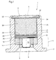
- An electrical ignition capsule 1 consists of a housing 2 on both sides has openings 4,5 closed by lacquer 3.
- An electrical ignition device 11 with pole bodies is located in a receiving bore 10 12,13 and insulating ring 14 located between them.
- One except in the middle horizontal ignition wire bridge 15 is with the pole bodies 12, 13 in a known manner soldered.
- An ignition charge 20 is pressed and encased on the electrical ignition device 11 the ignition wire bridge 15.
- the ignition charge 20 is made of a break-proof, but rapidly traveling plastic film 21 covered with high pressure polyethylene (HDPE).
- HDPE high pressure polyethylene
- a cup 25 is pressed into the receiving bore 10 and contains an ejection charge 26.
- the bowl 25 is formed on the bottom side as a sieve plate 28.
- the cross sections the gas flow openings 29 amount to 50% of the unspecified Cross section of the receiving bore 10.
- a flanged edge 32 fixes a ring 33 and a disk 34 Cup 25 is fixed and presses with a certain pre-tensioning force over the screen plate 28 the film 21 and the ignition charge 20 on the pole body 12, 13.
- the ignition capsule 1 has a relatively large discharge charge 26 and with the same length with the known igniter capsule. This will be mainly achieved by saving space by the ignition capsule according to the invention 1 has only a single ignition charge 20.
- the film 21 has the tasks of holding the primer 20 and for one to ensure even ignition of the primer 20.
- the ignition wire bridge 15 fires asymmetrically. Due to the braking, damaging effect of the film 21 the igniter 20 is ignited across its entire cross section. The The discharge charge 26 is therefore ignited through all gas flow openings 29 and not just part of it.
- the film 21 can also be made of plastic or metal, such as copper, aluminum or from a suitable composite material consist.
Landscapes
- Engineering & Computer Science (AREA)
- General Engineering & Computer Science (AREA)
- Air Bags (AREA)
- Ignition Installations For Internal Combustion Engines (AREA)
- Automotive Seat Belt Assembly (AREA)
Abstract
Description
Claims (5)
- Elektrische Anzündkapsel (1) mit einem Gehäuse (2), einer Ausstoßladung (26), einem Anzündsatz (20) und einer elektrischen Zündeinrichtung (12-15),
dadurch gekennzeichnet, daß zwischen der Ausstoßladung (26) und dem Anzündsatz (20) ein Siebblech (28) mit einer bruchfesten jedoch schnell reißenden Folie (21) aus Kunststoff angeordnet ist. - Anzündkapseln nach Anspruch 1,
dadurch gekennzeichnet, daß das Siebblech (28) Bestandteil eines Napfes (25) ist,
der Napf (25) die Ausstoßladung (26) umgibt, und
durch eingebörtelte Befestigungsteile (33,34) gesichert ist. - Anzündkapseln nach Anspruch 2,
dadurch gekennzeichnet, daß die Lochquerschnitte des Siebbleches 30-70 % des Querschnitts der Aufnahmebohrung (10) betragen. - Anzündkapseln nach Anspruch 1,
dadurch gekennzeichnet, daß eine Zünddrahtbrücke (15) im Anzündsatz (20) eingebettet ist. - Anzündkapsel nach Anspruch 1,
dadurch gekennzeichnet, daß die Kunstoff-Folie aus Hochdruckpolyäthylen (HDPE) oder aus einem anderen geeigneten Kunststoff oder Metall oder einem geeigneten Verbundwerkstoff besteht.
Applications Claiming Priority (2)
| Application Number | Priority Date | Filing Date | Title |
|---|---|---|---|
| DE10054779A DE10054779A1 (de) | 2000-11-04 | 2000-11-04 | Elektrische Anzündkapsel |
| DE10054779 | 2000-11-04 |
Publications (3)
| Publication Number | Publication Date |
|---|---|
| EP1203924A2 true EP1203924A2 (de) | 2002-05-08 |
| EP1203924A3 EP1203924A3 (de) | 2003-04-09 |
| EP1203924B1 EP1203924B1 (de) | 2008-03-19 |
Family
ID=7662187
Family Applications (1)
| Application Number | Title | Priority Date | Filing Date |
|---|---|---|---|
| EP01126079A Expired - Lifetime EP1203924B1 (de) | 2000-11-04 | 2001-11-02 | Elektrische Anzündkapsel |
Country Status (4)
| Country | Link |
|---|---|
| US (1) | US6568331B2 (de) |
| EP (1) | EP1203924B1 (de) |
| DE (2) | DE10054779A1 (de) |
| DK (1) | DK1203924T3 (de) |
Cited By (1)
| Publication number | Priority date | Publication date | Assignee | Title |
|---|---|---|---|---|
| CN103225992A (zh) * | 2013-04-10 | 2013-07-31 | 庄弘炜 | 一种声光爆震弹 |
Families Citing this family (4)
| Publication number | Priority date | Publication date | Assignee | Title |
|---|---|---|---|---|
| US6923122B2 (en) * | 2002-12-10 | 2005-08-02 | Reynolds Systems, Inc. | Energetic material initiation device utilizing exploding foil initiated ignition system with secondary explosive material |
| US7967333B2 (en) * | 2008-10-21 | 2011-06-28 | Autoliv Asp, Inc. | Inflator with ignition distribution |
| US8276516B1 (en) | 2008-10-30 | 2012-10-02 | Reynolds Systems, Inc. | Apparatus for detonating a triaminotrinitrobenzene charge |
| US8841567B1 (en) * | 2013-03-04 | 2014-09-23 | Omnitek Partners Llc | Compact and mechanical inertial igniters for thermal batteries and the like for munitions with short duration firing setback shock |
Family Cites Families (6)
| Publication number | Priority date | Publication date | Assignee | Title |
|---|---|---|---|---|
| US3541961A (en) * | 1968-12-03 | 1970-11-24 | Richard R Larson | Method and apparatus for preventing premature ignition of electro-explosive devices |
| US4150266A (en) * | 1977-01-27 | 1979-04-17 | Networks Electronic Corp. | Miniature pyrotechnic squib switch, single pole, normally open |
| US4386567A (en) * | 1981-07-28 | 1983-06-07 | The United States Of America As Represented By The Secretary Of The Army | Combination percussion-electric primer |
| US5603525A (en) * | 1995-06-22 | 1997-02-18 | Trw Inc. | Air bag inflator initiator housing with stored fluid pressure relief |
| EP0778181A3 (de) * | 1995-12-04 | 1999-04-14 | Morton International, Inc. | Airbag-Gasgenerator-Zünder |
| US5871346A (en) * | 1997-01-24 | 1999-02-16 | Eastman Kodak Company | Flashlamp array venting structure |
-
2000
- 2000-11-04 DE DE10054779A patent/DE10054779A1/de not_active Withdrawn
-
2001
- 2001-10-29 US US10/020,467 patent/US6568331B2/en not_active Expired - Fee Related
- 2001-11-02 DE DE50113752T patent/DE50113752D1/de not_active Expired - Fee Related
- 2001-11-02 EP EP01126079A patent/EP1203924B1/de not_active Expired - Lifetime
- 2001-11-02 DK DK01126079T patent/DK1203924T3/da active
Cited By (1)
| Publication number | Priority date | Publication date | Assignee | Title |
|---|---|---|---|---|
| CN103225992A (zh) * | 2013-04-10 | 2013-07-31 | 庄弘炜 | 一种声光爆震弹 |
Also Published As
| Publication number | Publication date |
|---|---|
| US20020056396A1 (en) | 2002-05-16 |
| EP1203924A3 (de) | 2003-04-09 |
| DE10054779A1 (de) | 2002-05-16 |
| US6568331B2 (en) | 2003-05-27 |
| EP1203924B1 (de) | 2008-03-19 |
| DE50113752D1 (de) | 2008-04-30 |
| DK1203924T3 (da) | 2008-06-09 |
Similar Documents
| Publication | Publication Date | Title |
|---|---|---|
| DE2629462C2 (de) | ||
| DE69802025T2 (de) | Pyrotechnischer Gasgenerator mit einstellbarem Durchsatz und Volumen für einen Airbag | |
| DE60023818T2 (de) | Gegen elektostatische Entladungen geschützter, pyrotechnischer Zünder mit durch Photoätzung hergestellter Zündbrücke | |
| DE69013075T2 (de) | Gehäuse mit zwei Schweissverbindungen für eine Gasbalgaufblasvorrichtung. | |
| EP0488937B1 (de) | Anzündeinheit, insbesondere für den Gasgenerator einer Kraftfahrzeuginsassen-Aufprallschutzvorrichtung | |
| DE3872175T2 (de) | Laengsfoermiger gaserzeuger zum aufblasen von aufblasbaren rueckhaltekissen in fahrzeugen. | |
| DE112016003039B4 (de) | Gasgenerator mit Wärme-Isolations-Schicht | |
| DE2832879A1 (de) | Treibladungsanzuender | |
| DE4138918A1 (de) | Gasgenerator, insbesondere rohrgasgenerator fuer airbag | |
| DE4201651A1 (de) | Selbstzuendungseinrichtung fuer eine airbagaufblasvorrichtung | |
| DE4324554B4 (de) | Gasgenerator, insbesondere für einen Airbag | |
| EP1104540B1 (de) | Zündelement mit einer laserlichtquelle | |
| DE19534076A1 (de) | Verfahren und Vorrichtung zum Aufblasen einer aufblasbaren Fahrzeuginsassenrückhaltevorrichtung | |
| DE3900931A1 (de) | Passives rueckhaltesystem | |
| EP0656522A1 (de) | Patronenhülse | |
| DE10054779A1 (de) | Elektrische Anzündkapsel | |
| WO1993018940A2 (de) | Gasgenerator-system | |
| DE112014004846T5 (de) | Brechbare Platte und diese verwendendes Aufblasglied | |
| DE2350104A1 (de) | Pyrochemischer gasgenerator | |
| DE4138988A1 (de) | Gasgenerator, insbesondere rohrgasgenerator fuer ein aufblasbares aufprallschutzkissen | |
| EP0891268B2 (de) | Gasgenerator | |
| DE3917460C1 (en) | Pyrotechnical gas producer - has central perforated cylinder and concentric cylinder | |
| DE2931765A1 (de) | Detonator ohne initialsprengstoff | |
| DE4116882A1 (de) | Anordnung einer gaserzeugenden masse in einem airbag | |
| DE2214477B2 (de) | Sprengscheibeneinheit |
Legal Events
| Date | Code | Title | Description |
|---|---|---|---|
| PUAI | Public reference made under article 153(3) epc to a published international application that has entered the european phase |
Free format text: ORIGINAL CODE: 0009012 |
|
| AK | Designated contracting states |
Kind code of ref document: A2 Designated state(s): AT BE CH CY DE DK ES FI FR GB GR IE IT LI LU MC NL PT SE TR |
|
| AX | Request for extension of the european patent |
Free format text: AL;LT;LV;MK;RO;SI |
|
| PUAL | Search report despatched |
Free format text: ORIGINAL CODE: 0009013 |
|
| AK | Designated contracting states |
Kind code of ref document: A3 Designated state(s): AT BE CH CY DE DK ES FI FR GB GR IE IT LI LU MC NL PT SE TR |
|
| AX | Request for extension of the european patent |
Extension state: AL LT LV MK RO SI |
|
| RIC1 | Information provided on ipc code assigned before grant |
Ipc: 7F 42C 19/08 A Ipc: 7F 42C 19/12 B |
|
| 17P | Request for examination filed |
Effective date: 20030415 |
|
| AKX | Designation fees paid |
Designated state(s): DE DK FR GB |
|
| RAP1 | Party data changed (applicant data changed or rights of an application transferred) |
Owner name: DIEHL BGT DEFENCE GMBH & CO.KG |
|
| 17Q | First examination report despatched |
Effective date: 20050318 |
|
| GRAP | Despatch of communication of intention to grant a patent |
Free format text: ORIGINAL CODE: EPIDOSNIGR1 |
|
| GRAS | Grant fee paid |
Free format text: ORIGINAL CODE: EPIDOSNIGR3 |
|
| GRAA | (expected) grant |
Free format text: ORIGINAL CODE: 0009210 |
|
| AK | Designated contracting states |
Kind code of ref document: B1 Designated state(s): DE DK FR GB |
|
| REG | Reference to a national code |
Ref country code: GB Ref legal event code: FG4D Free format text: NOT ENGLISH |
|
| REF | Corresponds to: |
Ref document number: 50113752 Country of ref document: DE Date of ref document: 20080430 Kind code of ref document: P |
|
| REG | Reference to a national code |
Ref country code: DK Ref legal event code: T3 |
|
| ET | Fr: translation filed | ||
| PLBE | No opposition filed within time limit |
Free format text: ORIGINAL CODE: 0009261 |
|
| STAA | Information on the status of an ep patent application or granted ep patent |
Free format text: STATUS: NO OPPOSITION FILED WITHIN TIME LIMIT |
|
| 26N | No opposition filed |
Effective date: 20081222 |
|
| REG | Reference to a national code |
Ref country code: DK Ref legal event code: EBP |
|
| GBPC | Gb: european patent ceased through non-payment of renewal fee |
Effective date: 20081102 |
|
| REG | Reference to a national code |
Ref country code: FR Ref legal event code: ST Effective date: 20090731 |
|
| PG25 | Lapsed in a contracting state [announced via postgrant information from national office to epo] |
Ref country code: DK Free format text: LAPSE BECAUSE OF NON-PAYMENT OF DUE FEES Effective date: 20081130 Ref country code: DE Free format text: LAPSE BECAUSE OF NON-PAYMENT OF DUE FEES Effective date: 20090603 |
|
| PG25 | Lapsed in a contracting state [announced via postgrant information from national office to epo] |
Ref country code: GB Free format text: LAPSE BECAUSE OF NON-PAYMENT OF DUE FEES Effective date: 20081102 |
|
| PG25 | Lapsed in a contracting state [announced via postgrant information from national office to epo] |
Ref country code: FR Free format text: LAPSE BECAUSE OF NON-PAYMENT OF DUE FEES Effective date: 20081130 |