EP1202795B1 - Procede de fabrication d'emulsions et ses dispositifs - Google Patents
Procede de fabrication d'emulsions et ses dispositifs Download PDFInfo
- Publication number
- EP1202795B1 EP1202795B1 EP00958582A EP00958582A EP1202795B1 EP 1202795 B1 EP1202795 B1 EP 1202795B1 EP 00958582 A EP00958582 A EP 00958582A EP 00958582 A EP00958582 A EP 00958582A EP 1202795 B1 EP1202795 B1 EP 1202795B1
- Authority
- EP
- European Patent Office
- Prior art keywords
- coherent jet
- phase
- dispersed phase
- emulsion
- jet
- Prior art date
- Legal status (The legal status is an assumption and is not a legal conclusion. Google has not performed a legal analysis and makes no representation as to the accuracy of the status listed.)
- Expired - Lifetime
Links
- 239000000839 emulsion Substances 0.000 title claims abstract description 77
- 238000000034 method Methods 0.000 title claims abstract description 21
- 230000001427 coherent effect Effects 0.000 claims abstract description 65
- 239000003995 emulsifying agent Substances 0.000 claims abstract description 60
- 239000012530 fluid Substances 0.000 claims abstract description 38
- 239000000203 mixture Substances 0.000 claims abstract description 18
- 238000002156 mixing Methods 0.000 claims abstract description 10
- XLYOFNOQVPJJNP-UHFFFAOYSA-N water Substances O XLYOFNOQVPJJNP-UHFFFAOYSA-N 0.000 claims description 30
- 238000004519 manufacturing process Methods 0.000 claims description 12
- 230000000694 effects Effects 0.000 claims description 10
- 238000007654 immersion Methods 0.000 claims description 7
- 239000012263 liquid product Substances 0.000 claims description 3
- 230000003068 static effect Effects 0.000 claims description 3
- 239000000654 additive Substances 0.000 claims description 2
- 230000000996 additive effect Effects 0.000 claims description 2
- 238000005086 pumping Methods 0.000 claims description 2
- 238000007599 discharging Methods 0.000 claims 3
- 230000001804 emulsifying effect Effects 0.000 claims 1
- 239000000126 substance Substances 0.000 claims 1
- 239000003921 oil Substances 0.000 description 26
- 235000019198 oils Nutrition 0.000 description 26
- 229920001213 Polysorbate 20 Polymers 0.000 description 19
- 239000000256 polyoxyethylene sorbitan monolaurate Substances 0.000 description 19
- 235000010486 polyoxyethylene sorbitan monolaurate Nutrition 0.000 description 19
- 239000012141 concentrate Substances 0.000 description 12
- 239000006260 foam Substances 0.000 description 12
- KEUKAQNPUBYCIC-UHFFFAOYSA-N ethaneperoxoic acid;hydrogen peroxide Chemical compound OO.CC(=O)OO KEUKAQNPUBYCIC-UHFFFAOYSA-N 0.000 description 10
- 235000019486 Sunflower oil Nutrition 0.000 description 7
- 239000002600 sunflower oil Substances 0.000 description 7
- 230000033228 biological regulation Effects 0.000 description 4
- 239000002270 dispersing agent Substances 0.000 description 4
- 238000000265 homogenisation Methods 0.000 description 4
- 230000036961 partial effect Effects 0.000 description 4
- 230000001105 regulatory effect Effects 0.000 description 4
- 241000208838 Asteraceae Species 0.000 description 3
- 238000013019 agitation Methods 0.000 description 3
- 230000008901 benefit Effects 0.000 description 3
- 238000004581 coalescence Methods 0.000 description 3
- 238000010586 diagram Methods 0.000 description 3
- 235000013305 food Nutrition 0.000 description 3
- 230000006641 stabilisation Effects 0.000 description 3
- 238000011105 stabilization Methods 0.000 description 3
- 238000010923 batch production Methods 0.000 description 2
- 238000010924 continuous production Methods 0.000 description 2
- 230000001687 destabilization Effects 0.000 description 2
- 238000004945 emulsification Methods 0.000 description 2
- 238000010438 heat treatment Methods 0.000 description 2
- 230000003993 interaction Effects 0.000 description 2
- 239000007788 liquid Substances 0.000 description 2
- 238000011144 upstream manufacturing Methods 0.000 description 2
- 230000003247 decreasing effect Effects 0.000 description 1
- 238000005516 engineering process Methods 0.000 description 1
- 238000005187 foaming Methods 0.000 description 1
- 230000000670 limiting effect Effects 0.000 description 1
- 239000007764 o/w emulsion Substances 0.000 description 1
- 239000003348 petrochemical agent Substances 0.000 description 1
- 230000005501 phase interface Effects 0.000 description 1
- 230000002829 reductive effect Effects 0.000 description 1
- 235000014438 salad dressings Nutrition 0.000 description 1
- 239000000523 sample Substances 0.000 description 1
- 238000005507 spraying Methods 0.000 description 1
Images



Classifications
-
- B—PERFORMING OPERATIONS; TRANSPORTING
- B01—PHYSICAL OR CHEMICAL PROCESSES OR APPARATUS IN GENERAL
- B01F—MIXING, e.g. DISSOLVING, EMULSIFYING OR DISPERSING
- B01F23/00—Mixing according to the phases to be mixed, e.g. dispersing or emulsifying
- B01F23/40—Mixing liquids with liquids; Emulsifying
- B01F23/41—Emulsifying
- B01F23/4105—Methods of emulsifying
-
- B—PERFORMING OPERATIONS; TRANSPORTING
- B01—PHYSICAL OR CHEMICAL PROCESSES OR APPARATUS IN GENERAL
- B01F—MIXING, e.g. DISSOLVING, EMULSIFYING OR DISPERSING
- B01F23/00—Mixing according to the phases to be mixed, e.g. dispersing or emulsifying
- B01F23/40—Mixing liquids with liquids; Emulsifying
- B01F23/45—Mixing liquids with liquids; Emulsifying using flow mixing
- B01F23/451—Mixing liquids with liquids; Emulsifying using flow mixing by injecting one liquid into another
-
- B—PERFORMING OPERATIONS; TRANSPORTING
- B01—PHYSICAL OR CHEMICAL PROCESSES OR APPARATUS IN GENERAL
- B01F—MIXING, e.g. DISSOLVING, EMULSIFYING OR DISPERSING
- B01F25/00—Flow mixers; Mixers for falling materials, e.g. solid particles
- B01F25/20—Jet mixers, i.e. mixers using high-speed fluid streams
- B01F25/23—Mixing by intersecting jets
-
- B—PERFORMING OPERATIONS; TRANSPORTING
- B01—PHYSICAL OR CHEMICAL PROCESSES OR APPARATUS IN GENERAL
- B01F—MIXING, e.g. DISSOLVING, EMULSIFYING OR DISPERSING
- B01F25/00—Flow mixers; Mixers for falling materials, e.g. solid particles
- B01F25/30—Injector mixers
- B01F25/31—Injector mixers in conduits or tubes through which the main component flows
- B01F25/313—Injector mixers in conduits or tubes through which the main component flows wherein additional components are introduced in the centre of the conduit
-
- B—PERFORMING OPERATIONS; TRANSPORTING
- B01—PHYSICAL OR CHEMICAL PROCESSES OR APPARATUS IN GENERAL
- B01F—MIXING, e.g. DISSOLVING, EMULSIFYING OR DISPERSING
- B01F33/00—Other mixers; Mixing plants; Combinations of mixers
- B01F33/80—Mixing plants; Combinations of mixers
- B01F33/834—Mixing in several steps, e.g. successive steps
-
- B—PERFORMING OPERATIONS; TRANSPORTING
- B01—PHYSICAL OR CHEMICAL PROCESSES OR APPARATUS IN GENERAL
- B01F—MIXING, e.g. DISSOLVING, EMULSIFYING OR DISPERSING
- B01F35/00—Accessories for mixers; Auxiliary operations or auxiliary devices; Parts or details of general application
- B01F35/71—Feed mechanisms
- B01F35/715—Feeding the components in several steps, e.g. successive steps
-
- B—PERFORMING OPERATIONS; TRANSPORTING
- B01—PHYSICAL OR CHEMICAL PROCESSES OR APPARATUS IN GENERAL
- B01F—MIXING, e.g. DISSOLVING, EMULSIFYING OR DISPERSING
- B01F2101/00—Mixing characterised by the nature of the mixed materials or by the application field
- B01F2101/06—Mixing of food ingredients
-
- B—PERFORMING OPERATIONS; TRANSPORTING
- B01—PHYSICAL OR CHEMICAL PROCESSES OR APPARATUS IN GENERAL
- B01F—MIXING, e.g. DISSOLVING, EMULSIFYING OR DISPERSING
- B01F2101/00—Mixing characterised by the nature of the mixed materials or by the application field
- B01F2101/22—Mixing of ingredients for pharmaceutical or medical compositions
Definitions
- the present invention relates to a method of manufacture of emulsions as well as an emulsifier this process.
- Such a process will find many applications, particularly in the fields of cosmetology, food industry for the making salad dressings for example, pharmacy, petrochemicals, etc.
- the manufacture of an emulsion consists of the mixture of two fluids, i.e. two liquids, determining two phases, by hypotheses not miscible, one being called dispersed phase and the other dispersing phase, one of which forms droplets microscopic in the other.
- This mixture or emulsion, and more particularly the size of the droplets of the dispersed phase in the dispersing phase depends in particular of energy supplied in the form of agitation to the medium which shears the fluid and thus allows the reduction in the size of the emulsion droplets.
- foam concentrates such as high pressure homogenizers or even "microfluidizers" producing emulsions comprising a emulsifier, for example an oil type emulsion in water.
- Homogenizers are conventionally made up a homogenization head and a high pressure pump to pressurize a fluid contained in a tank.
- the pressurized fluid is usually a pre-emulsion, i.e. it is a mixture partial of the dispersed phase, the dispersing phase and emulsifier; this fluid is then sent through the homogenization head mainly consisting of a base, valve and impact plates.
- the fluid is brutally relaxed through an appropriate opening, to reach a speed of the order of several hundreds of meters per second and then comes into contact with the valve which splits the fluid and projects it on the impact plates thus providing the necessary energy, in the form of agitation in the middle, for the manufacture of the emulsion.
- These homogenizers benefiting from current technologies operate at pressures up to 200 MPa.
- This module is mainly consisting of a cylindrical body each having its ends respectively a direct input block and an output block.
- the cylindrical body contains a succession of hollow and open cylindrical cartridges on one of their transverse faces and they are connected between them by springs.
- These cartridges contain a plurality of vibrating discs which can slide the along the central hollow axis of the cylindrical body of the module.
- microfluidizers conventionally made up of an interaction chamber and a high pressure pump to pressurize a fluid contained in a suitable reservoir.
- the fluid under pressure is usually a pre emulsion which is sent to the interaction room in which this last one is bombarded by itself with energy important brought by the pressurization of the fluid, this which allows the manufacture of the emulsion.
- a disadvantage of these devices is the important amount of emulsifier required to stabilize such emulsion. This high supply of emulsifier is then reflected by an excess of said emulsifier in the dispersing phase of the emulsion after its manufacture, which affects in particular the organoleptic qualities of the emulsion and increases the production costs.
- Document DE-A-2549026 describes, moreover, a emulsification process comprising the introduction of the dispersed phase in a jet of the dispersing phase and the mixing in a chamber of this jet with a part additional of the dispersing phase.
- Another disadvantage of all these devices is that provide an emulsion whose droplets have a average diameter of the order of a micrometer, which is not fully satisfactory for applications in food and cosmetology, by example.
- One of the aims of the invention is therefore to overcome these disadvantages by proposing a method of manufacturing a mixture or emulsion, for example of the oil type in water, to obtain greater fineness of the droplets using a minimum amount of emulsifier for stabilize said emulsion over time.
- the process for the continuous or batch production of a mixture or an emulsion from at least one emulsifier and at least two fluids known to be immiscible, for example a body fatty liquid mixed with water and an appropriate emulsifier, said fluids defining a dispersed phase and a dispersing phase is remarkable in that, the dispersed phase being either contained in a suitable tank, or delivered continuously, it comprises a first step of pressurizing the dispersed phase by conventional high-pressure pumping means, then a sudden depressurization of said dispersed phase is carried out using means making it possible to create a needle jet, that is to say a jet of narrow section, or coherent jet in which the dispersed phase can reach a speed of about 900 ms -1 . It is then conceivable to introduce the coherent jet of the dispersed phase into a dispersing phase in which an appropriate emulsifier has been dissolved to obtain the emulsion.
- the dispersed phase being either contained in a suitable tank,
- Such a method does not make it possible to obtain a size average droplet size small enough why, we prefer to introduce the appropriate emulsifier in said coherent jet by means ensuring the mixing the dispersed phase with said emulsifier.
- This resulting coherent jet is finally brought into contact with the dispersing phase to obtain the mixture or the emulsion.
- bringing the coherent jet into contact resulting with the dispersing phase is obtained by positioning said jet coherent resulting in immersion in the dispersing phase in a static or quasi-static position in means of racking.
- the implementation contact of the resulting coherent jet with the dispersing phase is obtained by means ensuring the introduction of the dispersing phase in said resulting coherent jet and simultaneously their emulsion which then constitutes a jet consistent final.
- the phase dispersed under pressure is regulated according to a range of temperature between -20 ° C and + 80 ° C so that the the emulsion is more homogeneous over time.
- the dispersed phase is pressurized to a pressure greater than or equal to 200 MPa.
- Another object of the invention relates to a device foam concentrate for continuous or batch production a mixture or an emulsion from at least one emulsifier and at least two fluids known to be immiscible, for example a fatty liquid product mixed with water and an emulsifier, said fluids defining a phase dispersed and a dispersing phase, and said device comprising a high pressure pump the inlet of which is connected to a fluid source such as a reservoir containing a dispersed phase;
- this device is remarkable in that the high pump output pressure is connected, by connection means, to means for projecting the dispersed phase in the form of a coherent jet cooperating with means of introduction, connected to an open tank and using the Venturi effect, of an emulsifier in said jet coherent emerging, in immersion, in the phase dispersant contained in means of continuous or discontinuous withdrawal of the emulsion.
- the pump outlet at high pressure is connected, by connection means, to means for projecting the phase dispersed under the form of a coherent jet, provided at their outlet with at least two introduction means which are mounted in series connected to an open tank respectively and using the Venturi effect, respectively at least the emulsifier in said coherent jet and phase dispersant in the resulting coherent jet, to provide the emulsion which is advantageously continuously recovered at the output of said introduction means or discontinuously.
- connection means between the high pressure pump and the projection means, are provided with temperature regulation means on all or part of their length.
- emulsion all mixtures and emulsions obtained according to the invention and by emulsifier all the mixing devices, homogenizer, "microfluidizer”, foam concentrate and homogenizer-emulsifier.
- the device for continuous or discontinuous emulsion which is represented on the Figures 1 to 4, includes a tank 1 containing a phase dispersed and the output of which is connected to a pump high pressure 2.
- a booster pump not shown on the figures, will advantageously be positioned between the tank 1 and the high pressure pump 2 to prime the latter in a conventional manner.
- connection means 3 to means of projection 4 of the dispersing phase in the form of a jet needle or coherent jet 5.
- the means of connection 3, between the high pressure pump 2 and the projection means 4 are provided with means for regulation 6 of the temperature of the dispersed phase, under pressure in said connection means 3, on all or part of their length.
- the output of the means of projection 4 is provided with introduction means 7 into the coherent jet 5 of an emulsifier contained in a second tank 8 connected to said means of introduction 7 of such so that when they come out a coherent jet resulting 9 consisting of the dispersed phase and the emulsifier.
- the resulting coherent jet 9 is then set contact with the dispersing phase contained in means withdrawal 10 continuously or discontinuously as is will see further.
- the resulting coherent throw 9 is preferably positioned in immersion in said phase dispersant to benefit from optimal energy, said resulting coherent jet, necessary to obtain a fine emulsion.
- the output of the introduction means 7 is provided with second introduction means 11, shown in dotted lines in FIG. 1, in the coherent jet resulting from a dispersing phase contained in a third tank 12, also shown in lines dashed in Figure 1, connected to said means introduction 11 so that when they come out a final coherent jet 13 consisting of the emulsion.
- the jet coherent final 13, i.e. the emulsion, is then collected continuously or discontinuously in the means of racking 10.
- the reservoir 1, containing the dispersed phase is connected to the high pump pressure 2 by a pipe 14.
- the high pressure pump 2 is advantageously a return pump which has a very short time constant which therefore does not present time out. It provides a pressure of 400 MPa while ensuring high flow and pressure constant.
- the connection means 3 between the pump high pressure 2 and the projection means 4, not shown in Figure 2 are constituted by a pipe armored 15 capable of carrying the dispersed pressurized phase and they have a branch circuit 16 provided with control valves 17 such as solenoid valves.
- the branch circuit 16 includes means for regulation 6 of the temperature of the dispersed phase pressurized, shown in dotted lines on the Figure 2.
- the regulating means 6 are, moreover, consisting of a coil of coils 18 surrounding the pipe shielded 15 on part of the branch circuit 16 and connected to a heat exchanger 19.
- the length of the coil 18 depends, in particular, on the heat coefficients of the fluid calorific circulating in said coil with turns 18 and of the dispersed phase used.
- the means of connection 3 may not include a circuit bypass 16 and the coil 18 will then be positioned directly around the armored pipe 15.
- the regulating means 6 comprise also a probe 20, preferably mounted upstream of the coil with turns 18 on the branch circuit 16, allowing to control the phase temperature dispersed in the armored pipe 15.
- the means projection 4 are conventionally mounted at the end of the armored pipe 15, facing the ground and they are made up a nozzle 21 supported by a nozzle holder 22 comprising a calibrated hole 23.
- the nozzle 21 is conventionally constituted a body 24 comprising at its lower end a second calibrated hole 25 and a needle 26 having a third hole calibrated 27 coaxial with first 23 and at second 25.
- the diameter of the calibrated hole 26 is advantageously between 0.08 and 0.15 mm for a pressure delivered by the high pressure pump 2 of 200 MPa in order to prevent said calibrated hole 26 from clogs.
- the projection means 4 can be directed upward to provide a straight stream.
- the nozzle 21 provides a needle jet, that is to say a jet of narrow section, or coherent jet 5 of the phase dispersed which is brutally depressurized and which gushes out in the introduction means 7.
- Said means introduction 7 are positioned at the lower end of the nozzle holder 22 and are constituted by a Venturi tube 28, with a length of about 15 mm for a pressure included between 200 MPa and 300 MPa, forming in its central part a mixing chamber 29 and at its lower end a focusing tube 30.
- the coherent jet 5 thus springs in the mixing chamber 29 where the emulsifier, initially contained in the reservoir 8 and which is brought, by a flexible conduit 31 provided with a control valve 17 and a flow control system 32, in the room 29 by Venturi effect, mix to provide in the focusing tube 30 a coherent jet resulting 9.
- the reservoir 8 is a reservoir open so that the emulsifier is under pressure atmospheric and can benefit from the Venturi effect for be brought into the mixing chamber 29. Furthermore, there it would be possible to introduce the emulsifier into the jet coherent dispersed phase by means of an incident jet making a very small angle with said coherent jet 5.
- the focusing tube 30 is positioned in immersion in a static or quasi-static dispersing phase contained in the withdrawal means 10 which are consisting of a main cylindrical container 33, a median cylindrical container 34 and a central cylinder 35 coaxial.
- the main cylindrical container 33 has the larger section and includes two openings 36.37 in its upper part for the introduction of a fluid calorific and two other openings 38.39 in its part lower for the output of said heat fluid, as we will see it later.
- the openings 36, 37, 38 and 39 of the main cylindrical container 33 are advantageously connected to the heat exchanger 19 by means of conventional connections not shown in the figures.
- the median cylindrical container 34 positioned inside of the main cylindrical container 33, includes a bottom reinforced 40 to avoid its deformation due to the pressure of the coherent jet resulting 9.
- the central cylinder 35 open to its two ends is positioned in the container cylindrical median 34 so that its end lower 41 is not in contact with the bottom reinforced 40. Furthermore, the cylindrical container median 34 and central cylinder 35 include respectively an opening 42 in its central part for drawing off the emulsion and an opening 43 in its upper part for the introduction of the phase dispersing as we will see later.
- the withdrawal means 10 can consist of a single cylindrical container comprising the dispersed phase and whether or not provided with a opening in its upper part for the introduction of the dispersing phase and another opening in its lower part for drawing off the emulsion either continuous, or discontinuous.
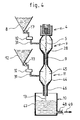
- the projection means 4 provide a coherent jet 5 which springs in a first Venturi tube 28 as described above allowing the mixture of the emulsifier, previously contained in the tank 8, with the phase dispersed and providing a jet coherent resulting 9 as already seen. Said jet resulting coherent 9 then springs into a second tube Venturi 44 mounted in series with the first 28 and forming a second mixing chamber 45 in its central part and a second focusing tube 46 in its lower part.
- the resulting coherent jet 9 thus flows in the second mixing chamber 45 where the dispersing phase, initially contained in the reservoir 12 then brought, by a conduit flexible 31 provided with a control valve 17 and a system flow control 32, in the second chamber mix 45 by Venturi effect, mix with said jet coherent resulting 9 to provide the flowing emulsion in the second focusing tube 46 in the form of a final coherent stream 13.
- the device can include several Venturi tubes mounted in series allowing to successively introduce into the coherent jet 5 several emulsifiers and several dispersing phases to manufacture so-called ternary emulsions such as water / oil / water type emulsions.
- the final coherent jet 13, that is to say the emulsion, is collected in the withdrawal means 10 placed at the vertical under the second focusing tube 46.
- the withdrawal means 10 then consist of a simple cylindrical container 47 provided with an opening 48 in its lower part to continuously draw the emulsion as indicated by arrow 49.
- the emulsion could be drawn off in discontinuous using a simple cylindrical container.
- FIGS. 2, 3, 5 and 6 The operation of the foam concentrate device according to the invention will now be explained with reference to FIGS. 2, 3, 5 and 6.
- the high-pressure pump 2 is primed which then pressurizes the oil in the armored pipe 15. Then actuates, if necessary, the various valves of control 17 so that the oil circulates in the bypass circuit 16 in order to regulate it in temperature.
- the pressurized oil spurts from the nozzle 21 (FIG. 3) to form a coherent jet 5 through the venturi tube 28.
- the oil is pressurized, preferably, at a pressure greater than or equal to 200 MPa so that the coherent jet 5 has sufficient energy to form the emulsion without the nozzle 21 becoming blocked.
- the oil speed can then reach 900 ms -1 for a pressure of 200 MPa and a diameter of the nozzle 21 of between 0.08 and 0.15 mm.
- Tween 20 the emulsifier used, Tween 20 being a registered trademark for an emulsifier. which we will call later "Tween 20".
- the "Tween 20" does not dissolve in the dispersed phase, that is to say the oil.
- the emulsifier dissolves only in the dispersing phase; thus, the "Tween 20" mixes with a homogeneously in coherent jet 5 without being there dissolves.
- the resulting coherent jet 9 is then introduced in immersion in water, corresponding to the dispersing phase, which is continuously injected into the central cylinder 35 through opening 43 as indicated by arrow 50 of the figure 3.
- the size of the emulsion droplets depends in particular on the energy brought in the form of agitation in the middle as we have already seen but also fluids used.
- the size of the droplets will depend in particular on the type of oil used.
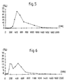
- Figure 5 shows the percentage of droplets according to their diameter, expressed in nanometer (nm) for an oil-in-water type emulsion, including 10% sunflower oil, 89% water and 1% of emulsifier "Tween 20", and obtained by projecting a jet sunflower oil, pressurized to 200 MPa, in water in which the "Tween 20" was previously dissolved.
- the general shape of the curve and the peak around 500 nm indicate that the average droplet diameter of the emulsion is between 500 and 600 nm.
- the graph in Figure 7 represents the destabilization expressed as a percentage, on the ordinate, which corresponds to the percentage of the quantity of the phase destabilized compared to its initial quantity, in function of the emulsifier / dispersed phase ratio, abscissa, i.e. the ratio of percentages emulsifier and dispersed phase of the emulsion.
- the curve in dotted lines corresponds to an emulsion obtained by introducing a jet of water, pressurized to 200 MPa, in oil in which been previously mixed the "Tween 20" and the curve in solid line corresponds to an emulsion obtained according to the invention.
- the stabilization i.e.
Landscapes
- Chemical & Material Sciences (AREA)
- Chemical Kinetics & Catalysis (AREA)
- Colloid Chemistry (AREA)
- Paper (AREA)
- Excavating Of Shafts Or Tunnels (AREA)
- Manufacture, Treatment Of Glass Fibers (AREA)
- Organic Low-Molecular-Weight Compounds And Preparation Thereof (AREA)
Description
- la figure 1 est une représentation schématique du dispositif émulseur selon l'invention,
- la figure 2 est un schéma partiel en légère perspective du dispositif émulseur selon l'invention comportant le réservoir de phase dispersée, la pompe à haute pression, les moyens de raccordement et les moyens de régulation de la température,
- la figure 3 est un schéma partiel de la première variante d'exécution du dispositif émulseur selon l'invention comportant les moyens de projection de la phase dispersée, les moyens d'introduction de l'émulsifiant dans le jet et les moyens de soutirage,
- la figure 4 est un schéma partiel de la seconde variante d'exécution du dispositif émulseur selon l'invention comportant les moyens de projection de la phase dispersée, deux moyens d'introduction respectivement de l'émulsifiant et de la phase dispersante montés en série et les moyens de soutirage,
- la figure 5 est un graphique représentant le pourcentage (%) des gouttelettes en fonction de leur diamètre exprimé en nanomètre (nm) pour un exemple d'émulsion du type huile dans eau, comprenant 10% d'huile de tournesol, 89% d'eau et 1% d'émulsifiant Tween 20 (marque déposée), et obtenue en projetant un jet d'huile de tournesol, pressurisée à 200 MPa, dans de l'eau dans laquelle a été préalablement dissout le Tween 20 (marque déposée),
- la figure 6 est un graphique représentant le pourcentage (%) des gouttelettes en fonction de leur diamètre exprimé en nanomètre (nm) pour une émulsion du type huile dans eau, comprenant 10% d'huile de tournesol, 89.5% d'eau et 0.5% d'émulsifiant Tween 20 (marque déposée) et obtenue selon le procédé.
- la figure 7 est un graphique représentant l'influence du rapport émulsifiant/phase dispersante sur la stabilité d'une émulsion du type eau dans huile.
Claims (10)
- Procédé de fabrication en continu ou en discontinu d'un mélange ou d'une émulsion à partir d'au moins un émulsifiant et au moins deux fluides réputés non miscibles, par exemple un corps gras mélangé à de l'eau et un émulsifiant approprié, lesdits fluides définissant une phase dispersée et une phase dispersante, caractérisé en ce que la phase dispersée étant soit contenue dans un réservoir adapté soit délivrée en continu, on exécute dans l'ordre au moins les étapes suivantes :la phase dispersée est mise sous pression par de classiques moyens de pompage haute pression puis,la phase dispersée est brutalement dépressurisée grâce à des moyens permettant de créer un jet cohérent (5) puis,un émulsifiant approprié est alors introduit dans ledit jet cohérent (5) grâce à des moyens assurant le mélange de la phase dispersée avec ledit émulsifiant et procurant ainsi un jet cohérent résultant (9) puis,ledit jet cohérent résultant (9) est mis en contact avec la phase dispersante pour obtenir, finalement, l'émulsion.
- Procédé selon la revendication 1 caractérisé en ce que le ou les fluides formant la phase dispersée est pressurisée à une pression supérieure ou égale à 200 MPa.
- Procédé selon l'une quelconque des revendications précédentes caractérisé en ce que la température de la phase dispersée sous pression est régulée selon une gamme de température comprise entre -20°C et +80°C.
- Procédé selon l'une quelconque des revendications précédentes caractérisé en ce que la mise en contact du jet cohérent résultant (9) avec la phase dispersante est obtenue en positionnant ledit jet cohérent résultant (9) en immersion dans la phase dispersante en position statique ou quasi statique.
- Procédé selon l'une quelconque des revendications 1 à 4 caractérisé en ce que la mise en contact du jet cohérent résultant (9) avec la phase dispersante est obtenue grâce à des moyens assurant l'introduction de la phase dispersante dans ledit jet cohérent résultant (9) et simultanément leur émulsion qui constitue alors un jet cohérent final (13).
- Dispositif pour la fabrication en continu ou en discontinu d'un mélange ou d'une émulsion à partir d'au moins un émulsifiant et au moins deux fluides réputés non miscibles, par exemple un produit liquide gras mélangé à de l'eau et un émulsifiant approprié, lesdits fluides définissant une phase dispersée et une phase dispersante, mettant en oeuvre le procédé selon la revendication 4 et comportant une pompe à haute pression (2) dont l'entrée est connectée à une source de fluide telle qu'un réservoir (1) contenant une phase dispersée, caractérisé en ce que la sortie de la pompe à haute pression (2) est reliée, par des moyens de raccordement (6), à des moyens de projection (4) de la phase dispersée sous la forme d'un jet cohérent (5) coopérant avec des moyens d'introduction (7), connecté à un réservoir ouvert (8) et utilisant l'effet Venturi, d'un émulsifiant dans ledit jet cohérent (5) pour former un jet cohérent résultant (9) dans un tube de focalisation (30) solidaire des moyens d'introduction (7) et débouchant, en immersion, dans la phase dispersante contenue dans des moyens de soutirage (10), en continu ou en discontinu, de l'émulsion.
- Dispositif pour la fabrication en continu ou en discontinu d'un mélange ou d'une émulsion à partir d'au moins un additif et au moins deux fluides réputés non miscibles, par exemple un produit liquide gras mélangé à de l'eau et un émulsifiant approprié, lesdits fluides définissant une phase dispersée et une phase dispersante, mettant en oeuvre le procédé selon la revendication 5 et comportant une pompe à haute pression (2) dont l'entrée est connectée à une source de fluide telle qu'un réservoir (1) contenant une phase dispersée, caractérisé en ce que la sortie de la pompe à haute pression (2) est reliée, par des moyens de raccordement (3), à des moyens de projection (4) de la phase dispersée sous la forme d'un jet cohérent (5), munis à leur sortie d'au moins deux moyens d'introduction (7,11) qui sont montés en série, reliés à un réservoir ouvert respectivement (8) et (12) et utilisant l'effet Venturi, respectivement au moins de l'émulsifiant dans ledit et cohérent (5) pour former un et cohérent résultant (9) et de la phase dispersante dans ledit jet cohérent résultant (9) pour former un jet cohérent final (13) et procurer ainsi l'émulsion qui est récupérée en continu ou en discontinu à la sortie des seconds moyens d'introduction (11) par des moyens de soutirage (10).
- Dispositif émulseur selon l'une quelconque des revendications 6 et 7 caractérisé en ce que les moyens de raccordement (3), entre la pompe à haute pression (2) et les moyens de projection (4), sont munis de moyens de régulation de la température (6) sur tout ou partie de leur longueur.
- Dispositif émulseur selon la revendication 8 caractérisé en ce que les moyens de régulation de la température (6) sont constitués d'une sonde de température (20) positionnée sur les moyens de raccordement (3) et d'un serpentin à spires (18), connecté à un échangeur calorifique (13), qui entoure lesdits moyens de raccordement (3).
- Dispositif émulseur selon l'une quelconque des revendications 6 à 9 caractérisé en ce que les moyens de soutirage (10) sont munis de moyens de régulation de la température (33,36,37,38,39) connecté à l'échangeur calorifique (13).
Applications Claiming Priority (3)
| Application Number | Priority Date | Filing Date | Title |
|---|---|---|---|
| FR9909448 | 1999-07-21 | ||
| FR9909448A FR2796568B1 (fr) | 1999-07-21 | 1999-07-21 | Procede de fabrication d'emulsions et son dispositif |
| PCT/FR2000/002106 WO2001005493A1 (fr) | 1999-07-21 | 2000-07-21 | Procede de fabrication d'emulsions et son dispositif |
Publications (2)
| Publication Number | Publication Date |
|---|---|
| EP1202795A1 EP1202795A1 (fr) | 2002-05-08 |
| EP1202795B1 true EP1202795B1 (fr) | 2004-06-16 |
Family
ID=9548342
Family Applications (1)
| Application Number | Title | Priority Date | Filing Date |
|---|---|---|---|
| EP00958582A Expired - Lifetime EP1202795B1 (fr) | 1999-07-21 | 2000-07-21 | Procede de fabrication d'emulsions et ses dispositifs |
Country Status (7)
| Country | Link |
|---|---|
| EP (1) | EP1202795B1 (fr) |
| AT (1) | ATE269148T1 (fr) |
| AU (1) | AU7005600A (fr) |
| CA (1) | CA2379754A1 (fr) |
| DE (1) | DE60011623D1 (fr) |
| FR (1) | FR2796568B1 (fr) |
| WO (1) | WO2001005493A1 (fr) |
Families Citing this family (2)
| Publication number | Priority date | Publication date | Assignee | Title |
|---|---|---|---|---|
| FR3066946B1 (fr) * | 2017-05-30 | 2022-12-16 | Michelin & Cie | Melange continu en phase liquide pour la production de composites destines a une utilisation dans des produits elastomeriques |
| FR3066947B1 (fr) * | 2017-05-30 | 2020-12-11 | Michelin & Cie | Malaxage d'un composite elastomerique par melange continu en phase liquide |
Family Cites Families (6)
| Publication number | Priority date | Publication date | Assignee | Title |
|---|---|---|---|---|
| CH559574A5 (en) * | 1973-10-18 | 1975-03-14 | Maier Kurt | Continuously metering detergent into running water - for washing cars using jet induction and mixing |
| DE2549086A1 (de) * | 1975-11-03 | 1977-05-18 | Helmut Mueller | Verfahren und vorrichtung zur herstellung von emulsionen |
| ZA767406B (en) * | 1975-12-22 | 1977-11-30 | Ici Ltd | Method of dispersing an oil slick |
| GB2076672A (en) * | 1980-02-18 | 1981-12-09 | Unilever Ltd | Making foam |
| JPH02504600A (ja) * | 1988-04-25 | 1990-12-27 | インゼネルヌイ、ツェントル、“トランズブク” | 乳濁液を製造するための方法および装置 |
| EP0616002B1 (fr) * | 1992-09-18 | 1998-03-04 | Idemitsu Petrochemical Co., Ltd. | Procede de production de poudre de polycarbonate |
-
1999
- 1999-07-21 FR FR9909448A patent/FR2796568B1/fr not_active Expired - Fee Related
-
2000
- 2000-07-21 AT AT00958582T patent/ATE269148T1/de not_active IP Right Cessation
- 2000-07-21 WO PCT/FR2000/002106 patent/WO2001005493A1/fr not_active Ceased
- 2000-07-21 AU AU70056/00A patent/AU7005600A/en not_active Abandoned
- 2000-07-21 DE DE60011623T patent/DE60011623D1/de not_active Expired - Fee Related
- 2000-07-21 CA CA002379754A patent/CA2379754A1/fr not_active Abandoned
- 2000-07-21 EP EP00958582A patent/EP1202795B1/fr not_active Expired - Lifetime
Also Published As
| Publication number | Publication date |
|---|---|
| EP1202795A1 (fr) | 2002-05-08 |
| CA2379754A1 (fr) | 2001-01-25 |
| WO2001005493A8 (fr) | 2001-04-12 |
| DE60011623D1 (de) | 2004-07-22 |
| FR2796568A1 (fr) | 2001-01-26 |
| FR2796568B1 (fr) | 2001-09-21 |
| AU7005600A (en) | 2001-02-05 |
| ATE269148T1 (de) | 2004-07-15 |
| WO2001005493A1 (fr) | 2001-01-25 |
Similar Documents
| Publication | Publication Date | Title |
|---|---|---|
| EP0676244B1 (fr) | Dispositif de pulvérisation d'un liquide, notamment d'un liquide à haute viscosité, à l'aide d'au moins un gaz auxiliaire | |
| EP0869841A1 (fr) | Dispositif de generation de mousse | |
| CN106861477B (zh) | 高密度微细气泡液生成方法及高密度微细气泡液生成装置 | |
| EP1551540B1 (fr) | Procede et dispositif de fabrication d'une dispersion ou d'une emulsion | |
| EP1051464B1 (fr) | Procede de preparation d'un combustible emulsionne et son dispositif de mise en oeuvre | |
| FR2958186A1 (fr) | Dispositif de formation de gouttes dans un circuit microfluide. | |
| FR2722711A1 (fr) | Appareil et procede pour augmenter le debit d'ecoulement d'un liquide, tel qu'un polymere fondu, a travers un orifice | |
| JP2011528278A (ja) | 剪断力、乱流、及び/又はキャビテーションの生成によって液体を混合するための装置及び方法 | |
| WO2010052388A1 (fr) | Procede de formation d'une emulsion a partir de liquides non miscibles en eux et application a l'alimentation en liquide d'un dispositif de nebulisation | |
| CA2379754A1 (fr) | Procede de fabrication d'emulsions et son dispositif | |
| EP1338330A2 (fr) | Dispositif de mélange et d'homogénéisation destiné à la production d'émulsions | |
| FR3020578A1 (fr) | Dispositif d'injection, notamment pour injecter une charge d'hydrocarbures dans une unite de raffinage. | |
| EP3600647B1 (fr) | Dispositif d'injection de charge ameliore pour une unite fcc | |
| FR2623730A1 (fr) | Installation de fabrication de mousses, notamment pour la realisation d'elements de construction cellulaires permettant la fabrication de mousses avec de tres faibles proportions d'agent emulsifiant comprises entre 1 et 15 pour mille | |
| JP2014133207A (ja) | 連続相中に分散相が分散した組成物の製造方法およびその装置 | |
| EP3113867B1 (fr) | Procédé et dispositif de dispersion de gaz dans un liquide | |
| FR2750347A1 (fr) | Procede de production de mousse optimise et reglable, ainsi que l'appareil concu a cet effet | |
| EP3946709A1 (fr) | Procédés de production de poudre par séchage par atomisation | |
| FR3072126A1 (fr) | Systemes d'alimentation en combustible liquide d'un systeme de combustion, notamment d'une turbine a gaz, comprenant un dispositif de generation d'une emulsion et de repartition du debit d'emulsion | |
| EP3902625A1 (fr) | Dispositif et procede pour creer une emulsion | |
| EP4186585A1 (fr) | Dispositif de dispersion de polymeres hydrosolubles | |
| FR3040312A1 (fr) | Procede de traitement en continu d'un melange | |
| BE526229A (fr) | ||
| BE510572A (fr) | ||
| FR2924033A1 (fr) | Procede d'obtention d'une dispersion d'au moins une huile essentielle dans l'eau. |
Legal Events
| Date | Code | Title | Description |
|---|---|---|---|
| PUAI | Public reference made under article 153(3) epc to a published international application that has entered the european phase |
Free format text: ORIGINAL CODE: 0009012 |
|
| 17P | Request for examination filed |
Effective date: 20020220 |
|
| AK | Designated contracting states |
Kind code of ref document: A1 Designated state(s): AT BE CH CY DE DK ES FI FR GB GR IE IT LI LU MC NL PT SE |
|
| AX | Request for extension of the european patent |
Free format text: AL;LT;LV;MK;RO;SI |
|
| GRAH | Despatch of communication of intention to grant a patent |
Free format text: ORIGINAL CODE: EPIDOS IGRA |
|
| RTI1 | Title (correction) |
Free format text: METHOD FOR MAKING EMULSIONS AND IMPLEMENTING DEVICES |
|
| GRAH | Despatch of communication of intention to grant a patent |
Free format text: ORIGINAL CODE: EPIDOS IGRA |
|
| GRAA | (expected) grant |
Free format text: ORIGINAL CODE: 0009210 |
|
| AK | Designated contracting states |
Kind code of ref document: B1 Designated state(s): AT BE CH CY DE DK ES FI FR GB GR IE IT LI LU MC NL PT SE |
|
| PG25 | Lapsed in a contracting state [announced via postgrant information from national office to epo] |
Ref country code: IT Free format text: LAPSE BECAUSE OF FAILURE TO SUBMIT A TRANSLATION OF THE DESCRIPTION OR TO PAY THE FEE WITHIN THE PRESCRIBED TIME-LIMIT;WARNING: LAPSES OF ITALIAN PATENTS WITH EFFECTIVE DATE BEFORE 2007 MAY HAVE OCCURRED AT ANY TIME BEFORE 2007. THE CORRECT EFFECTIVE DATE MAY BE DIFFERENT FROM THE ONE RECORDED. Effective date: 20040616 Ref country code: CY Free format text: LAPSE BECAUSE OF FAILURE TO SUBMIT A TRANSLATION OF THE DESCRIPTION OR TO PAY THE FEE WITHIN THE PRESCRIBED TIME-LIMIT Effective date: 20040616 Ref country code: NL Free format text: LAPSE BECAUSE OF FAILURE TO SUBMIT A TRANSLATION OF THE DESCRIPTION OR TO PAY THE FEE WITHIN THE PRESCRIBED TIME-LIMIT Effective date: 20040616 Ref country code: IE Free format text: LAPSE BECAUSE OF FAILURE TO SUBMIT A TRANSLATION OF THE DESCRIPTION OR TO PAY THE FEE WITHIN THE PRESCRIBED TIME-LIMIT Effective date: 20040616 Ref country code: AT Free format text: LAPSE BECAUSE OF FAILURE TO SUBMIT A TRANSLATION OF THE DESCRIPTION OR TO PAY THE FEE WITHIN THE PRESCRIBED TIME-LIMIT Effective date: 20040616 Ref country code: FI Free format text: LAPSE BECAUSE OF FAILURE TO SUBMIT A TRANSLATION OF THE DESCRIPTION OR TO PAY THE FEE WITHIN THE PRESCRIBED TIME-LIMIT Effective date: 20040616 Ref country code: GB Free format text: LAPSE BECAUSE OF FAILURE TO SUBMIT A TRANSLATION OF THE DESCRIPTION OR TO PAY THE FEE WITHIN THE PRESCRIBED TIME-LIMIT Effective date: 20040616 |
|
| REG | Reference to a national code |
Ref country code: GB Ref legal event code: FG4D Free format text: NOT ENGLISH |
|
| REG | Reference to a national code |
Ref country code: CH Ref legal event code: EP |
|
| PG25 | Lapsed in a contracting state [announced via postgrant information from national office to epo] |
Ref country code: LU Free format text: LAPSE BECAUSE OF NON-PAYMENT OF DUE FEES Effective date: 20040721 |
|
| REF | Corresponds to: |
Ref document number: 60011623 Country of ref document: DE Date of ref document: 20040722 Kind code of ref document: P |
|
| REG | Reference to a national code |
Ref country code: IE Ref legal event code: FG4D Free format text: FRENCH |
|
| PG25 | Lapsed in a contracting state [announced via postgrant information from national office to epo] |
Ref country code: MC Free format text: LAPSE BECAUSE OF NON-PAYMENT OF DUE FEES Effective date: 20040731 Ref country code: BE Free format text: LAPSE BECAUSE OF NON-PAYMENT OF DUE FEES Effective date: 20040731 Ref country code: CH Free format text: LAPSE BECAUSE OF NON-PAYMENT OF DUE FEES Effective date: 20040731 Ref country code: LI Free format text: LAPSE BECAUSE OF NON-PAYMENT OF DUE FEES Effective date: 20040731 |
|
| PG25 | Lapsed in a contracting state [announced via postgrant information from national office to epo] |
Ref country code: DK Free format text: LAPSE BECAUSE OF FAILURE TO SUBMIT A TRANSLATION OF THE DESCRIPTION OR TO PAY THE FEE WITHIN THE PRESCRIBED TIME-LIMIT Effective date: 20040916 Ref country code: GR Free format text: LAPSE BECAUSE OF FAILURE TO SUBMIT A TRANSLATION OF THE DESCRIPTION OR TO PAY THE FEE WITHIN THE PRESCRIBED TIME-LIMIT Effective date: 20040916 Ref country code: SE Free format text: LAPSE BECAUSE OF FAILURE TO SUBMIT A TRANSLATION OF THE DESCRIPTION OR TO PAY THE FEE WITHIN THE PRESCRIBED TIME-LIMIT Effective date: 20040916 |
|
| PG25 | Lapsed in a contracting state [announced via postgrant information from national office to epo] |
Ref country code: ES Free format text: LAPSE BECAUSE OF FAILURE TO SUBMIT A TRANSLATION OF THE DESCRIPTION OR TO PAY THE FEE WITHIN THE PRESCRIBED TIME-LIMIT Effective date: 20040927 |
|
| LTIE | Lt: invalidation of european patent or patent extension |
Effective date: 20040616 |
|
| NLV1 | Nl: lapsed or annulled due to failure to fulfill the requirements of art. 29p and 29m of the patents act | ||
| GBV | Gb: ep patent (uk) treated as always having been void in accordance with gb section 77(7)/1977 [no translation filed] |
Effective date: 20040616 |
|
| REG | Reference to a national code |
Ref country code: IE Ref legal event code: FD4D |
|
| BERE | Be: lapsed |
Owner name: UNIVERSITE DE BOURGOGNE Effective date: 20040731 Owner name: AMORE MAILLE Effective date: 20040731 |
|
| PG25 | Lapsed in a contracting state [announced via postgrant information from national office to epo] |
Ref country code: DE Free format text: LAPSE BECAUSE OF NON-PAYMENT OF DUE FEES Effective date: 20050201 |
|
| REG | Reference to a national code |
Ref country code: CH Ref legal event code: PL |
|
| PLBE | No opposition filed within time limit |
Free format text: ORIGINAL CODE: 0009261 |
|
| STAA | Information on the status of an ep patent application or granted ep patent |
Free format text: STATUS: NO OPPOSITION FILED WITHIN TIME LIMIT |
|
| 26N | No opposition filed |
Effective date: 20050317 |
|
| REG | Reference to a national code |
Ref country code: FR Ref legal event code: TP |
|
| BERE | Be: lapsed |
Owner name: *UNIVERSITE DE BOURGOGNE Effective date: 20040731 Owner name: *AMORE MAILLE Effective date: 20040731 |
|
| PG25 | Lapsed in a contracting state [announced via postgrant information from national office to epo] |
Ref country code: PT Free format text: LAPSE BECAUSE OF NON-PAYMENT OF DUE FEES Effective date: 20041116 |
|
| PGFP | Annual fee paid to national office [announced via postgrant information from national office to epo] |
Ref country code: FR Payment date: 20070727 Year of fee payment: 8 |
|
| REG | Reference to a national code |
Ref country code: FR Ref legal event code: ST Effective date: 20090331 |
|
| PG25 | Lapsed in a contracting state [announced via postgrant information from national office to epo] |
Ref country code: FR Free format text: LAPSE BECAUSE OF NON-PAYMENT OF DUE FEES Effective date: 20080731 |