EP1201927B1 - Vacuum pump - Google Patents
Vacuum pump Download PDFInfo
- Publication number
- EP1201927B1 EP1201927B1 EP20010124365 EP01124365A EP1201927B1 EP 1201927 B1 EP1201927 B1 EP 1201927B1 EP 20010124365 EP20010124365 EP 20010124365 EP 01124365 A EP01124365 A EP 01124365A EP 1201927 B1 EP1201927 B1 EP 1201927B1
- Authority
- EP
- European Patent Office
- Prior art keywords
- vacuum pump
- flow path
- cover
- bellows
- piping mechanism
- Prior art date
- Legal status (The legal status is an assumption and is not a legal conclusion. Google has not performed a legal analysis and makes no representation as to the accuracy of the status listed.)
- Expired - Lifetime
Links
Images


Classifications
-
- F—MECHANICAL ENGINEERING; LIGHTING; HEATING; WEAPONS; BLASTING
- F04—POSITIVE - DISPLACEMENT MACHINES FOR LIQUIDS; PUMPS FOR LIQUIDS OR ELASTIC FLUIDS
- F04C—ROTARY-PISTON, OR OSCILLATING-PISTON, POSITIVE-DISPLACEMENT MACHINES FOR LIQUIDS; ROTARY-PISTON, OR OSCILLATING-PISTON, POSITIVE-DISPLACEMENT PUMPS
- F04C29/00—Component parts, details or accessories of pumps or pumping installations, not provided for in groups F04C18/00 - F04C28/00
- F04C29/12—Arrangements for admission or discharge of the working fluid, e.g. constructional features of the inlet or outlet
-
- F—MECHANICAL ENGINEERING; LIGHTING; HEATING; WEAPONS; BLASTING
- F04—POSITIVE - DISPLACEMENT MACHINES FOR LIQUIDS; PUMPS FOR LIQUIDS OR ELASTIC FLUIDS
- F04C—ROTARY-PISTON, OR OSCILLATING-PISTON, POSITIVE-DISPLACEMENT MACHINES FOR LIQUIDS; ROTARY-PISTON, OR OSCILLATING-PISTON, POSITIVE-DISPLACEMENT PUMPS
- F04C18/00—Rotary-piston pumps specially adapted for elastic fluids
- F04C18/08—Rotary-piston pumps specially adapted for elastic fluids of intermeshing-engagement type, i.e. with engagement of co-operating members similar to that of toothed gearing
- F04C18/12—Rotary-piston pumps specially adapted for elastic fluids of intermeshing-engagement type, i.e. with engagement of co-operating members similar to that of toothed gearing of other than internal-axis type
- F04C18/126—Rotary-piston pumps specially adapted for elastic fluids of intermeshing-engagement type, i.e. with engagement of co-operating members similar to that of toothed gearing of other than internal-axis type with radially from the rotor body extending elements, not necessarily co-operating with corresponding recesses in the other rotor, e.g. lobes, Roots type
-
- F—MECHANICAL ENGINEERING; LIGHTING; HEATING; WEAPONS; BLASTING
- F04—POSITIVE - DISPLACEMENT MACHINES FOR LIQUIDS; PUMPS FOR LIQUIDS OR ELASTIC FLUIDS
- F04C—ROTARY-PISTON, OR OSCILLATING-PISTON, POSITIVE-DISPLACEMENT MACHINES FOR LIQUIDS; ROTARY-PISTON, OR OSCILLATING-PISTON, POSITIVE-DISPLACEMENT PUMPS
- F04C29/00—Component parts, details or accessories of pumps or pumping installations, not provided for in groups F04C18/00 - F04C28/00
- F04C29/06—Silencing
- F04C29/065—Noise dampening volumes, e.g. muffler chambers
Definitions
- the present invention relates to a flow path structure for a vacuum pump in which a gas delivering body in a pump chamber is activated based on rotation of a rotating shaft so that gas is caused to flow through the operation of the gas delivering body to thereby provide a sucking operation.
- Vibrations of the main body of a vacuum pump are transmitted, by suction piping for sucking gas into the main body of the vacuum pump and discharge piping for discharging gas, from the main body of the vacuum pump.
- the vibrations are then transmitted to auxiliary equipment to which the suction piping or discharging piping is connected, and the auxiliary equipment is vibrated, whereby the level of noise is increased.
- a bellows is interposed on the suction piping or the discharge piping.
- the bellows so interposed on the suction piping or discharge piping absorbs the transmitted vibrations.
- the pressure within the suction piping varies from the atmospheric pressure to a negative pressure which is close to zero.
- a check valve is disposed at the discharge piping.
- the pressure within the discharge piping from the main body of the vacuum pump to the check valve varies from a positive pressure which is higher than the atmospheric pressure, to a negative pressure which is close to zero.
- the pressure within the discharge piping downstream of the check valve varies from a positive pressure, which is higher than the atmospheric pressure, to the atmospheric pressure.
- the bellows In a case where a bellows is used as part of the suction piping or discharge piping whose pressure varies as has been just described, the bellows is elastically deformed to extend or contract by virtue of the change in internal pressure of the bellows. A load from the elastic deformation extends to the auxiliary equipment and this may cause a risk that the auxiliary equipment is damaged.
- An object of the present invention is to provide a flow path structure in which a load generated when a bellows constituting part of the gas flow path of a vacuum pump is elastically deformed by virtue of the change in the pressure in the bellows, does not extend to auxiliary equipment to which the vacuum pump is connected via the bellows.
- a flow path structure for a vacuum pump in which a gas delivering mechanism in a pump chamber is activated based on rotation of a rotating shaft so that gas is delivered through operation of said gas delivering body to thereby provide a sucking operation
- said flow path structure comprising a piping mechanism constituting a gas flow path for said gas and connected to a housing of a main body of said vacuum pump in such a manner to communicate with said pump chamber, a bellows constituting at least part of said piping mechanism, and a cover, incorporating therein said main body of said vacuum pump, and adapted to fix said piping mechanism, wherein said bellows is incorporated in said cover.
- a load generated in association with the elastic deformation of the bellows in the cover is received and absorbed by the cover. Consequently, the load generated in association with the elastic deformation does not extend to auxiliary equipment of the vacuum pump.
- the bellows is disposed so as to be inclined relative to the rotating shaft.
- the construction in which the bellows is disposed so as to be inclined relative to the rotating shaft, is advantageous in making the overall length of the bellows as long as possible.
- the piping mechanism is disposed linearly along an external wall surface of the housing of the main body of the vacuum pump.
- the linear piping mechanism is advantageous in making the apparatus compact.
- the piping mechanism is made substantially parallel to the rotating shaft.
- Vibrations of the vacuum pump are mainly generated in a direction normal to the rotating shaft.
- the bellows of the piping mechanism which is substantially parallel to the rotating shaft extends and/or contracts in axial directions of the rotating shaft, and consequently the disposition of the bellows is the most effective to absorb vibrations of the vacuum pump.
- a through-hole is formed in the cover, the piping mechanism passes through the through-hole, and a seal means is disposed to be joined to the piping mechanism and the cover, to seal between the interior and exterior of the cover.
- the through-hole does not constitute a portion which provides communication between the interior and exterior of the cover, whereby the sealing properties within the cover can be secured.
- a front housing 13 is joined to a front end of a rotor housing 12 of a multi-stage Roots pump 11, and a seal body 36 is joined to the front housing 13.
- a rear housing 14 is joined to a rear end of the rotor housing 12.
- the rotor housing 12 comprises a cylinder block 15 and a plurality of partitions 16.
- the cylinder block 15 comprises a pair of block pieces 17, 18, and the partition 16 comprises a pair of wall pieces 161, 162.
- a space between the front housing 13 and the partition 16 spaces between the adjacent partitions 16 and a space between the rear housing 14 and the partitions 16 constitute pump chambers 66, 67, 68, 69, 70, respectively.
- a rotating shaft 19 is rotatably supported on the front housing 13 and the rear housing 14 via radial bearings 21, 37.
- a rotating shaft 20 is rotatably supported on the front housing 13 and the rear housing 14 via radial bearings 22, 38. Both the rotating shafts 19, 20 are disposed horizontally parallel to each other. The rotating shafts 19, 20 are passed through the partitions 16.
- a plurality of rotors 23, 24, 25, 26, 27 are integrally formed on the rotating shaft 19, and a plurality of rotors 28, 29, 30, 31, 32 are integrally formed on the rotating shaft 20.
- the rotors 23 to 32 are formed in the same configuration and size when viewed in a direction along axes 191, 201 of the rotating shafts 19, 20.
- the thicknesses of the rotors 23, 24, 25, 26, 27 are reduced in that order, and the thicknesses of the rotors 28, 29, 30, 31, 32 are reduced in that order.
- the rotors 23, 28 are accommodated in the pump chamber 66 in a state in which they mesh with each other
- the rotors 24, 29 are accommodated in the pump chamber 67 in a state in which they mesh with each other
- the rotors 25, 30 are accommodated in the pump chamber 68 in a state in which they mesh with each other
- the rotors 26, 31 are accommodated in the pump chamber 69 in a state in which they mesh with each other
- the rotors 27, 32 are accommodated in the pump chamber 70 in a state in which they mesh with each other.
- a gear housing 33 is assembled to the rear housing 14.
- the rotating shafts 19, 20 pass through the rear housing 14 and protrude into the gear housing 33, and gears 34, 35 are securely fastened to protruding ends of the rotating shafts 19, 20, respectively, in a state in which they mesh with each other.
- An electric motor M is assembled to the gear housing 33.
- the driving force of the electric motor M is transmitted to the rotating shaft 19 via an axial joint 10, and the rotating shaft 19 is rotated in a direction indicated by arrows R1 in Figs. 5A, 5B and Figs. 6A, 6B.
- the rotating shaft 20 obtains the driving force from the electric motor M via the gears 34, 35 and rotates in a direction indicated by arrows R2 in Figs. 5A, 5B and Figs. 6A, 6B, which is an opposite direction to the rotating direction of the rotating shaft 19.
- a passage 163 is formed in the partition 16.
- an inlet 164 and an outlet 165 of the passage 163 are formed in the partition 16.
- the adjacent pump chambers 66, 67, 68, 69, 70 are allowed to communicate with each other via the passages 163.
- an introduction port 171 is formed in the block piece 17 in such a manner as to communicate with the pump chamber 66.
- a discharge port 181 is formed in the block piece 18 in such a manner as to communicate with the pump chamber 70.
- Gas introduced into the pump chamber 66 from the introduction port 171 is delivered into the passage 163 from the inlet 164 by virtue of rotation of the rotors 23, 28, and then is delivered out from the outlet 165 into the adjacent pump chamber 67 by way of the passage 163.
- the gas is delivered in the order in which the capacities of the pump chambers are decreased, that is, in the order of the pump chambers 67, 68, 69, and 70.
- the gas that has been delivered to the pump chamber 70 is then discharged to the outside from the discharge port 181.
- the rotors 23 to 32 are a gas delivering mechanism for delivering the gas.
- the rotor housing 12, the front housing 13, the rear housing 14 and the gear housing 33 constitute a housing of a main body of the multi-stage Roots pump. As shown in Figs. 1 and 2, the main body of the multi-stage Roots pump is incorporated in a cover 47, which is securely fastened to fixing portions of a place where the apparatus is installed.
- a connecting flange 39 is connected to the discharge port 181.
- a muffler 40 is connected to the connecting flange 39, and a cylindrical guide pipe 41 is connected to the muffler 40.
- a discharge pipe 42 is connected to the guide pipe 41.
- a through hole 471 is formed in an upper portion of a wall 473 of the cover 47 in front of the front housing 13, and the discharge pipe 42 is passed through the through hole 471.
- the discharge pipe 42 passes through the cover 47 and then connects to an exhaust gas processing device, not shown.
- a bellows 421 is incorporated in series with the discharge pipe 42.
- the bellows 421 is spaced apart from the housing constituting the main body of the multi-stage Roots pump 11.
- a mounting flange 422 is formed around an outer circumference of the discharge pipe 42. The mounting flange 422 is fixed to the cover 47 by tightening screws 57, and the bellows 421 is incorporated in the cover 47.
- the connecting flange 39, the muffler 40, the guide pipe 41 and the discharge pipe 42 are disposed linearly along an external wall surface of the rotor housing 12 in such a manner as to become substantially parallel to the rotating shafts 19, 20.
- the connecting flange 39, the muffler 40, the guide pipe 41 and the discharge pipe 42, which are disposed linearly, constitute a discharge piping mechanism 64 for delivering exhaust gas, that is discharged from the multi-stage Roots pump 11, to the exhaust gas processing device.
- the discharge piping mechanism 64 is connected to the rotor housing 12 constituting the housing of the main body of the multi-stage Roots pump 11 in such a manner as to communicate with the pump chamber 70.
- a valve body 43 and a return spring 44 are accommodated in the guide pipe 41.
- a tapered valve hole 411 is formed in the guide pipe 41, and the valve body 43 is adapted to open/close the valve hole 411.
- the guide pipe 41, the valve body 43 and the return spring 44 constitutes a reverse flow preventing means. Exhaust gas discharged from the pump chamber 70 having the smallest capacity of all the pump chambers to the connecting flange 39, by way of the discharge port 181, reaches the valve hole 411 by way of the muffler 40.
- a connecting flange 58 is connected to an introduction port 171.
- a suction pipe 59 is connected to the connecting flange 58.
- a through hole 472 is provided in a lower portion of the wall 473 of the cover 47, and the suction pipe 59 is passed through the through hole 472.
- the suction pipe 59 passes through the cover 47 to be connected to a target suction device, not shown.
- a bellows 591 is incorporated in the suction pipe 59 in series. The bellows 591 is spaced apart from the housing constituting the main body of the multi-stage Roots pump 11.
- a mounting flange 592 is formed around an outer circumference of the suction pipe 59. The mounting flange 592 is fixed to the cover 47 by tightening screws 60, the bellows 591 is incorporated in the cover 47.
- the connecting flange 58 and the suction pipe 59 are disposed linearly along the external wall surface of the rotor housing 12 in such a manner as to become substantially parallel to the rotating shafts 19, 20.
- the connecting flange 58 and the suction pipe 59 constitute a suction piping mechanism 65 for delivering exhaust gases sucked from the target suction device to the multi-stage Roots pump 11.
- the suction piping mechanism 65 is connected to the rotor housing 12 constituting the housing of the main body of the multi-stage Roots pump 11 in such a manner as to communicate with the pump chamber 66.
- the multi-stage Roots pump 11 is accommodated in the cover 47.
- legs 111 are formed on a lower surface of the multi-stage Roots pump 11.
- the legs 111 are connected to a bottom wall of the cover 47 via rubber cushions 61, respectively.
- a controller 48 and an inverter 49 for controlling the electric motor M mounted in the cover 47 are a controller 48 and an inverter 49 for controlling the electric motor M.
- a cooler 50 is placed on a lower surface of the rear housing 14.
- a cooler 51 is placed on an upper surface of the controller 48, and a cooler 52 is placed on an upper surface of the inverter 49.
- Cooling fluid is delivered to a main supply pipe 53 from a cooling fluid supply source, not shown.
- the cooling fluid delivered to the main supply pipe 53 passes through the cooler 51 and the cooler 52 in that order.
- an electromagnetic three-way valve 55 is in a deexcited state, the cooling fluid that has passed through the cooler 52 is refluxed to the cooling fluid supply source by way of the main supply pipe 53.
- the cooling fluid that has passed through the cooler 51 flows to the cooler 50 side by way of a sub-supply pipe 54.
- a temperature detector 56 attached to a surface of the rear housing 14 detects the temperature of the surface of the rear housing 14.
- the controller 48 control excites and/or deexcites the electromagnetic three-way valve 55 based on temperature detection information obtained from the temperature detector 56. Namely, the controller 48 controls the exciting and/or de-exciting of the magnetic three-way valve 55 so that the temperature on the surface of the rear housing 14 reaches a predetermined temperature.
- a seal member 62 is interposed between a mounting flange 422 and a wall 473, and a seal member 63 is interposed between a mounting flange 592 and the wall 473.
- the seal member 62 is joined to the mounting flange 422 and the wall 473, and constitutes a seal means for cutting off communications between the interior and exterior of the cover 47 through a through hole 471.
- the seal member 63 is joined to the mounting flange 592 and the wall 473, and constitutes a seal means for cutting off communications between the interior and exterior of the cover 47 through a through hole 472.
- a bellows 421 which is part of a discharge pipe 42A constituting a discharge piping mechanism 64A is disposed in such a manner as to be inclined relative to rotating shafts 191, 201 (not shown).
- a bellows 591 which is part of a suction pipe 59A constituting a suction piping mechanism 65A is disposed in such a manner as to be inclined relative to rotating shafts 191, 201 (not shown).
- the construction in which the bellows 421, 591 are disposed in such a manner as to be inclined relative to the rotating shafts 191, 201 is advantageous in making the overall lengths of the bellows 421, 591 as long as possible without extending the length of the main body of the multi-stage Roots pump in the axial direction thereof. The more the bellows 421, 591 extend, the more advantageous it is in absorbing vibrations of the main body of the multi-stage Roots pump.
- the bellows constituting at least part of the piping mechanisms are incorporated in the cover, and the piping mechanisms are connected to the cover.
- the present invention provides a superior advantage that the loads generated when the bellows constituting part of the gas flow path of the vacuum pump are elastically deformed, by virtue of the change in internal pressures, can be prevented from extending to the auxiliary equipment.
Description
- The present invention relates to a flow path structure for a vacuum pump in which a gas delivering body in a pump chamber is activated based on rotation of a rotating shaft so that gas is caused to flow through the operation of the gas delivering body to thereby provide a sucking operation.
- Vibrations of the main body of a vacuum pump are transmitted, by suction piping for sucking gas into the main body of the vacuum pump and discharge piping for discharging gas, from the main body of the vacuum pump. The vibrations are then transmitted to auxiliary equipment to which the suction piping or discharging piping is connected, and the auxiliary equipment is vibrated, whereby the level of noise is increased. In order that the vibrations of the main body of the vacuum pump are not transmitted directly to the auxiliary equipment through the suction piping or discharge piping, it is considered as a measure against the problem that a bellows is interposed on the suction piping or the discharge piping. The bellows so interposed on the suction piping or discharge piping absorbs the transmitted vibrations. This suppresses the vibration of the auxiliary equipment, which in turn suppresses the noise level. Such an arrangement is known from JP-A-56,038598. Further, the use of bellows in piping associated with vacuum pumps are known from JP-A-04,031675.
- The pressure within the suction piping varies from the atmospheric pressure to a negative pressure which is close to zero. On the discharge piping, in order to suppress discharge pulsation, a check valve is disposed at the discharge piping. In this case, the pressure within the discharge piping from the main body of the vacuum pump to the check valve varies from a positive pressure which is higher than the atmospheric pressure, to a negative pressure which is close to zero. In addition, the pressure within the discharge piping downstream of the check valve varies from a positive pressure, which is higher than the atmospheric pressure, to the atmospheric pressure. An atmospheric atmosphere is present in a pump chamber of the vacuum pump before the vacuum pump starts to operate, and the positive pressure higher than the atmospheric pressure is generated when the atmospheric atmosphere is compressed immediately after the vacuum pump starts to operate. In a case where a bellows is used as part of the suction piping or discharge piping whose pressure varies as has been just described, the bellows is elastically deformed to extend or contract by virtue of the change in internal pressure of the bellows. A load from the elastic deformation extends to the auxiliary equipment and this may cause a risk that the auxiliary equipment is damaged.
- An object of the present invention is to provide a flow path structure in which a load generated when a bellows constituting part of the gas flow path of a vacuum pump is elastically deformed by virtue of the change in the pressure in the bellows, does not extend to auxiliary equipment to which the vacuum pump is connected via the bellows.
- With a view to attaining the object, according to one aspect of the present invention, there is provided a flow path structure for a vacuum pump in which a gas delivering mechanism in a pump chamber is activated based on rotation of a rotating shaft so that gas is delivered through operation of said gas delivering body to thereby provide a sucking operation, said flow path structure comprising
a piping mechanism constituting a gas flow path for said gas and connected to a housing of a main body of said vacuum pump in such a manner to communicate with said pump chamber,
a bellows constituting at least part of said piping mechanism, and
a cover, incorporating therein said main body of said vacuum pump, and adapted to fix said piping mechanism,
wherein said bellows is incorporated in said cover. - A load generated in association with the elastic deformation of the bellows in the cover is received and absorbed by the cover. Consequently, the load generated in association with the elastic deformation does not extend to auxiliary equipment of the vacuum pump.
- According to one embodiment, the bellows is disposed so as to be inclined relative to the rotating shaft.
- The construction in which the bellows is disposed so as to be inclined relative to the rotating shaft, is advantageous in making the overall length of the bellows as long as possible.
- According to a further embodiment, the piping mechanism is disposed linearly along an external wall surface of the housing of the main body of the vacuum pump.
- The linear piping mechanism is advantageous in making the apparatus compact.
- According to a still further embodiment, the piping mechanism is made substantially parallel to the rotating shaft.
- Vibrations of the vacuum pump are mainly generated in a direction normal to the rotating shaft. The bellows of the piping mechanism which is substantially parallel to the rotating shaft extends and/or contracts in axial directions of the rotating shaft, and consequently the disposition of the bellows is the most effective to absorb vibrations of the vacuum pump.
- According to a yet further embodiment, a through-hole is formed in the cover, the piping mechanism passes through the through-hole, and a seal means is disposed to be joined to the piping mechanism and the cover, to seal between the interior and exterior of the cover.
- The through-hole does not constitute a portion which provides communication between the interior and exterior of the cover, whereby the sealing properties within the cover can be secured.
- The present invention may be more fully understood from the description of preferred embodiments of the invention, as set forth below, together with the accompanying drawings.
- In the drawings;
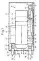
- Fig. 1 is a side view of a multi-stage Roots pump placed in a cover according to a first embodiment of the present invention,
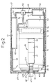
- Fig. 2 is a plan view of the multi-stage Roots pump in the cover shown in Fig. 1,
- Fig. 3A is a cross-sectional side view of a main portion of a discharge piping mechanism, and Fig. 3B is a cross-sectional side view of a main portion of a suction piping mechanism,
- Fig. 4 is a longitudinally horizontally cross-sectional view of the multi-stage Roots pump,
- Fig. 5A is a cross-sectional view taken along the line A-A in Fig. 4, and Fig. 5B is a cross-sectional view taken along the line B-B in Fig. 4,
- Fig. 6A is a cross-sectional view taken along the line C-C in Fig. 4, and Fig. 6B is a cross-sectional view taken along the line D-D in Fig. 4,
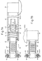
- Figs. 7A, 7B show a second embodiment according to the present invention, in which Fig. 7A is a cross-sectional side view showing a main portion of a discharge piping mechanism, and Fig. 7B is a cross-sectional side view showing a main portion of a suction piping mechanism, and
- Figs. 8A, 8B show a third embodiment according to the present invention, in which Fig. 8A is a cross-sectional side view showing a main portion of a discharge piping mechanism, and Fig. 8B is a cross-sectional side view showing a main portion of a suction piping mechanism.
-
- A first embodiment of the present invention in which the invention is embodied in a Roots pump will be described below with reference to Figs. 1 to 6B.
- As shown in Fig. 4, a
front housing 13 is joined to a front end of arotor housing 12 of amulti-stage Roots pump 11, and aseal body 36 is joined to thefront housing 13. Arear housing 14 is joined to a rear end of therotor housing 12. Therotor housing 12 comprises acylinder block 15 and a plurality ofpartitions 16. As shown in Fig. 5B, thecylinder block 15 comprises a pair ofblock pieces partition 16 comprises a pair ofwall pieces front housing 13 and thepartition 16, spaces between theadjacent partitions 16 and a space between therear housing 14 and thepartitions 16 constitutepump chambers - A rotating
shaft 19 is rotatably supported on thefront housing 13 and therear housing 14 viaradial bearings shaft 20 is rotatably supported on thefront housing 13 and therear housing 14 viaradial bearings rotating shafts shafts partitions 16. - A plurality of
rotors rotating shaft 19, and a plurality ofrotors rotating shaft 20. Therotors 23 to 32 are formed in the same configuration and size when viewed in a direction alongaxes rotating shafts rotors rotors rotors pump chamber 66 in a state in which they mesh with each other, therotors rotors pump chamber 68 in a state in which they mesh with each other, therotors pump chamber 69 in a state in which they mesh with each other, and therotors pump chamber 70 in a state in which they mesh with each other. - A
gear housing 33 is assembled to therear housing 14. The rotatingshafts rear housing 14 and protrude into thegear housing 33, and gears 34, 35 are securely fastened to protruding ends of therotating shafts gear housing 33. The driving force of the electric motor M is transmitted to therotating shaft 19 via an axial joint 10, and therotating shaft 19 is rotated in a direction indicated by arrows R1 in Figs. 5A, 5B and Figs. 6A, 6B. The rotatingshaft 20 obtains the driving force from the electric motor M via thegears rotating shaft 19. - As shown in Figs. 4 and 5B, a
passage 163 is formed in thepartition 16. As shown in Fig. 5B, aninlet 164 and anoutlet 165 of thepassage 163 are formed in thepartition 16. Theadjacent pump chambers passages 163. - As shown in Fig. 5A, an
introduction port 171 is formed in theblock piece 17 in such a manner as to communicate with thepump chamber 66. As shown in Fig. 6B, adischarge port 181 is formed in theblock piece 18 in such a manner as to communicate with thepump chamber 70. Gas introduced into thepump chamber 66 from theintroduction port 171 is delivered into thepassage 163 from theinlet 164 by virtue of rotation of therotors outlet 165 into the adjacent pump chamber 67 by way of thepassage 163. Thus, similarly, the gas is delivered in the order in which the capacities of the pump chambers are decreased, that is, in the order of thepump chambers pump chamber 70 is then discharged to the outside from thedischarge port 181. Therotors 23 to 32 are a gas delivering mechanism for delivering the gas. - The
rotor housing 12, thefront housing 13, therear housing 14 and thegear housing 33 constitute a housing of a main body of the multi-stage Roots pump. As shown in Figs. 1 and 2, the main body of the multi-stage Roots pump is incorporated in acover 47, which is securely fastened to fixing portions of a place where the apparatus is installed. - As shown in Fig. 6B, a connecting
flange 39 is connected to thedischarge port 181. As shown in Fig. 3A, amuffler 40 is connected to the connectingflange 39, and acylindrical guide pipe 41 is connected to themuffler 40. Adischarge pipe 42 is connected to theguide pipe 41. A throughhole 471 is formed in an upper portion of awall 473 of thecover 47 in front of thefront housing 13, and thedischarge pipe 42 is passed through the throughhole 471. Thedischarge pipe 42 passes through thecover 47 and then connects to an exhaust gas processing device, not shown. A bellows 421 is incorporated in series with thedischarge pipe 42. The bellows 421 is spaced apart from the housing constituting the main body of the multi-stage Roots pump 11. A mountingflange 422 is formed around an outer circumference of thedischarge pipe 42. The mountingflange 422 is fixed to thecover 47 by tighteningscrews 57, and thebellows 421 is incorporated in thecover 47. - The connecting
flange 39, themuffler 40, theguide pipe 41 and thedischarge pipe 42 are disposed linearly along an external wall surface of therotor housing 12 in such a manner as to become substantially parallel to therotating shafts flange 39, themuffler 40, theguide pipe 41 and thedischarge pipe 42, which are disposed linearly, constitute adischarge piping mechanism 64 for delivering exhaust gas, that is discharged from the multi-stage Roots pump 11, to the exhaust gas processing device. Thedischarge piping mechanism 64 is connected to therotor housing 12 constituting the housing of the main body of the multi-stage Roots pump 11 in such a manner as to communicate with thepump chamber 70. - A
valve body 43 and areturn spring 44 are accommodated in theguide pipe 41. A taperedvalve hole 411 is formed in theguide pipe 41, and thevalve body 43 is adapted to open/close thevalve hole 411. Theguide pipe 41, thevalve body 43 and thereturn spring 44 constitutes a reverse flow preventing means. Exhaust gas discharged from thepump chamber 70 having the smallest capacity of all the pump chambers to the connectingflange 39, by way of thedischarge port 181, reaches thevalve hole 411 by way of themuffler 40. In a case where a load, applied to a closingend wall 45 of thevalve body 43 by the pressure inside themuffler 40, exceeds a load applied to the closingend wall 45 by the pressure inside theguide pipe 41 and the spring force of thereturn spring 44, thevalve body 43 opens thevalve hole 411. Exhaust gases that have passed through thevalve hole 411, flow to thedischarge pipe 42 side through the circumference of acircumferential wall 46 of thevalve body 43 and acommunication hole 461. - As shown in Fig. 5A, a connecting
flange 58 is connected to anintroduction port 171. As shown in Fig. 3B, asuction pipe 59 is connected to the connectingflange 58. A throughhole 472 is provided in a lower portion of thewall 473 of thecover 47, and thesuction pipe 59 is passed through the throughhole 472. Thesuction pipe 59 passes through thecover 47 to be connected to a target suction device, not shown. A bellows 591 is incorporated in thesuction pipe 59 in series. The bellows 591 is spaced apart from the housing constituting the main body of the multi-stage Roots pump 11. A mountingflange 592 is formed around an outer circumference of thesuction pipe 59. The mountingflange 592 is fixed to thecover 47 by tighteningscrews 60, thebellows 591 is incorporated in thecover 47. - The connecting
flange 58 and thesuction pipe 59 are disposed linearly along the external wall surface of therotor housing 12 in such a manner as to become substantially parallel to therotating shafts flange 58 and thesuction pipe 59 constitute asuction piping mechanism 65 for delivering exhaust gases sucked from the target suction device to the multi-stage Roots pump 11. Thesuction piping mechanism 65 is connected to therotor housing 12 constituting the housing of the main body of the multi-stage Roots pump 11 in such a manner as to communicate with thepump chamber 66. - As shown in Figs. 1 and 2, the multi-stage Roots pump 11 is accommodated in the
cover 47. As shown in Fig. 1,legs 111 are formed on a lower surface of the multi-stage Roots pump 11. Thelegs 111 are connected to a bottom wall of thecover 47 via rubber cushions 61, respectively. - As shown in Fig. 2, mounted in the
cover 47 are acontroller 48 and aninverter 49 for controlling the electric motor M. A cooler 50 is placed on a lower surface of therear housing 14. A cooler 51 is placed on an upper surface of thecontroller 48, and a cooler 52 is placed on an upper surface of theinverter 49. Cooling fluid is delivered to amain supply pipe 53 from a cooling fluid supply source, not shown. The cooling fluid delivered to themain supply pipe 53 passes through the cooler 51 and the cooler 52 in that order. In a case where an electromagnetic three-way valve 55 is in a deexcited state, the cooling fluid that has passed through the cooler 52 is refluxed to the cooling fluid supply source by way of themain supply pipe 53. On the contrary, in a case where the electromagnetic three-way valve 55 is in an excited state, the cooling fluid that has passed through the cooler 51 flows to the cooler 50 side by way of asub-supply pipe 54. Atemperature detector 56 attached to a surface of therear housing 14 detects the temperature of the surface of therear housing 14. Thecontroller 48 control excites and/or deexcites the electromagnetic three-way valve 55 based on temperature detection information obtained from thetemperature detector 56. Namely, thecontroller 48 controls the exciting and/or de-exciting of the magnetic three-way valve 55 so that the temperature on the surface of therear housing 14 reaches a predetermined temperature. - The following advantages are obtained from the first embodiment.
- (1) The vibrations of the main body of the multi-stage
Roots pump 11 generated in association with the
rotation of the
rotors 23 to 32 are transmitted through thesuction piping mechanism 65 and thedischarge piping mechanism 64. The vibrations of the main body of the multi-stage Roots pump 11, which are transmitted through thesuction piping mechanism 65, are absorbed by thebellows 591. The vibrations of the main body of the multi-stage Roots pump 11, which are transmitted through thedischarge piping mechanism 64, are absorbed by thebellows 421. The pressure in thesuction piping mechanism 65 varies from atmospheric pressure to a negative pressure which is close to zero. The pressure in thedischarge piping mechanism 64 from the main body of the multi-stage Roots pump 11 to thevalve body 43 changes from a positive pressure, which is equal to or higher than the atmospheric pressure, to a negative pressure which is close to zero. In addition, the pressure in thedischarge piping mechanism 64 downstream of thevalve body 43 varies from a positive pressure, which is higher than the atmospheric pressure, to atmospheric pressure. The atmospheric atmosphere is present in thepump chambers 66 to 70 before the multi-stage Roots pump starts to operate, and the positive pressure, which is equal to or higher than the atmospheric pressure, is generated when the atmospheric atmosphere is compressed immediately after the multi-stage Roots pump has started to operate. Thebellows bellows cover 47, and the loads generated in association with the elastic deformations of thebellows cover 47 are received and absorbed by thecover 47. Consequently, the loads generated in association with the elastic deformations of thebellows - (2) The
discharge piping mechanism 64 and thesuction piping mechanism 65 are disposed linearly along the external wall surface of therotor housing 12 constituting the housing of the main body of the multi-stage Roots pump 11. The construction, in which thedischarge piping mechanism 64 and thesuction piping mechanism 65 are disposed linearly along the external wall surface of therotor housing 12, can ensure that an exclusive space for peripheral attachments to the main body of the multi-stage Roots pump 11 is small. Consequently, acompact cover 47 can be adopted, and this makes the multi-stage Roots pump 11 itself, including thecover 47, compact. - (3) The vibrations of the multi-stage Roots pump 11
are mainly generated in the direction normal to the
rotating shafts bellows 421 of thedischarge piping mechanism 64, which is substantially parallel to therotating shafts bellows 591 of thesuction piping mechanism 65, which are substantially parallel to therotating shafts axes rotating shafts bellows bellows bellows rotating shafts -
- Next, a second embodiment shown in Figs. 7A, 7B will be described. The same reference numerals will be imparted to constituent components similar to those described in the first embodiment.
- A
seal member 62 is interposed between a mountingflange 422 and awall 473, and aseal member 63 is interposed between a mountingflange 592 and thewall 473. Theseal member 62 is joined to the mountingflange 422 and thewall 473, and constitutes a seal means for cutting off communications between the interior and exterior of thecover 47 through a throughhole 471. Theseal member 63 is joined to the mountingflange 592 and thewall 473, and constitutes a seal means for cutting off communications between the interior and exterior of thecover 47 through a throughhole 472. There is no gap in thecover 47 and the interior of thecover 47 is completely sealed by thecover 47. Consequently, even if there should occur a leakage of exhaust gases from the main body of the multi-stage Roots pump 11, thesuction piping mechanism 65 or thedischarge piping mechanism 64, the gas that has so leaked can be sealed in thecover 47. - Next, a third embodiment illustrated in Figs. 8A, 8B will be described. The same reference numerals will be imparted to constituent components similar to those described in the first embodiment.
- A bellows 421 which is part of a
discharge pipe 42A constituting adischarge piping mechanism 64A is disposed in such a manner as to be inclined relative torotating shafts 191, 201 (not shown). A bellows 591 which is part of asuction pipe 59A constituting asuction piping mechanism 65A is disposed in such a manner as to be inclined relative torotating shafts 191, 201 (not shown). The construction in which thebellows rotating shafts bellows bellows - The following embodiments may be provided according to the present invention.
- (1) The bellows are directly joined to the cover.
- (2) The
muffler 40 may be made to function as a bellows on the discharge piping mechanism side. In this case, themuffler 40 and theguide pipe 41 need to be spaced apart from the housing of the main body of the multi-stage Roots pump. - (3) The piping mechanism for forming the gas flow
path inside the
cover 47 may be connected to the internal surface of thecover 47 in such a manner as to communicate with the through hole in thecover 47, and the piping mechanism for forming the gas flow path outside thecover 47 is connected to the external surface of the cover in such a manner as to communicate with the through hole in thecover 47. - (4) The present invention may be applied to vacuum pumps other than Roots pumps.
-
- As has been described heretofore, according to the present invention, the bellows constituting at least part of the piping mechanisms are incorporated in the cover, and the piping mechanisms are connected to the cover. Thus, the present invention provides a superior advantage that the loads generated when the bellows constituting part of the gas flow path of the vacuum pump are elastically deformed, by virtue of the change in internal pressures, can be prevented from extending to the auxiliary equipment.
Claims (8)
- A flow path structure for a vacuum pump in which a gas delivering mechanism in a pump chamber is activated based on rotation of a rotating shaft (191, 201) so that gas is delivered through operation of said gas delivering body to thereby provide a sucking operation, said flow path structure comprising
a piping mechanism (64, 65) constituting a gas flow path for said gas and connected to a housing (12) of a main body of said vacuum pump (11) in such a manner to communicate with said pump chamber (66, 67, 68, 69, 70),
a bellows (421, 591) constituting at least part of said piping mechanism; characterised by
a cover (47), incorporating therein said main body of said vacuum pump, and adapted to fix said piping mechanism (64, 65),
wherein said bellows (421, 591) is incorporated in said cover (47). - A flow path structure for a vacuum pump, as set forth in Claim 1, wherein said bellows is disposed in such a manner as to be inclined relative to said rotating shaft (191, 201).
- A flow path structure for a vacuum pump, as set forth in Claim 1, wherein said piping mechanism is disposed linearly along an external wall surface of said housing (12) of said main body of said vacuum pump.
- A flow path structure for a vacuum pump, as set forth in Claim 1, wherein said piping mechanism is made substantially parallel to said rotating shaft.
- A flow path structure for a vacuum pump, as set forth in any of Claims 1 to 4, wherein a through hole (471, 472) is formed in said cover (47), and said piping mechanism (64, 65) passes through said through-hole, and wherein a seal mechanism (62, 63) is disposed to be joined to said piping mechanism and said cover, to seal between the interior and exterior of said cover.
- A flow path structure for a vacuum pump, as set forth in any of Claims 1 to 5, wherein said piping mechanism (64, 65) is a discharge piping mechanism (64) constituting a gas flow path on a discharge side.
- A flow path structure for a vacuum pump, as set forth in any of Claims 1 to 5, wherein said piping mechanism (64, 65) is a suction piping mechanism (65) constituting a gas flow path on a suction side.
- A flow path structure for a vacuum pump as set forth in any of Claims 1 to 7, wherein said vacuum pump is a vacuum pump in which a plurality of said rotating shafts (191, 201) are disposed in parallel to each other, in which rotors (23, 32) as said gas delivering mechanism are disposed on each of said plurality of said rotating shafts, in which said rotors on said rotating shafts which are adjacent to each other are made to mesh with each other, and in which a plurality of pump chambers (66, 67, 68, 69, 70) or a single pump chamber is provided in which said rotors which are in a state in which said rotors mesh with each other are accommodated as a set.
Applications Claiming Priority (2)
| Application Number | Priority Date | Filing Date | Title |
|---|---|---|---|
| JP2000322577 | 2000-10-23 | ||
| JP2000322577A JP2002130170A (en) | 2000-10-23 | 2000-10-23 | Channel structure in vacuum pump |
Publications (3)
| Publication Number | Publication Date |
|---|---|
| EP1201927A2 EP1201927A2 (en) | 2002-05-02 |
| EP1201927A3 EP1201927A3 (en) | 2003-01-22 |
| EP1201927B1 true EP1201927B1 (en) | 2004-09-01 |
Family
ID=18800431
Family Applications (1)
| Application Number | Title | Priority Date | Filing Date |
|---|---|---|---|
| EP20010124365 Expired - Lifetime EP1201927B1 (en) | 2000-10-23 | 2001-10-23 | Vacuum pump |
Country Status (3)
| Country | Link |
|---|---|
| EP (1) | EP1201927B1 (en) |
| JP (1) | JP2002130170A (en) |
| DE (1) | DE60105249T2 (en) |
Families Citing this family (7)
| Publication number | Priority date | Publication date | Assignee | Title |
|---|---|---|---|---|
| JP3922140B2 (en) | 2002-09-06 | 2007-05-30 | 株式会社豊田自動織機 | Fluid pump device |
| JP3896930B2 (en) | 2002-09-10 | 2007-03-22 | 株式会社豊田自動織機 | Fluid pump device |
| JP4007130B2 (en) * | 2002-09-10 | 2007-11-14 | 株式会社豊田自動織機 | Vacuum pump |
| JP3991918B2 (en) * | 2003-05-19 | 2007-10-17 | 株式会社豊田自動織機 | Roots pump |
| JP4702236B2 (en) * | 2006-09-12 | 2011-06-15 | 株式会社豊田自動織機 | Vacuum pump shutdown control method and shutdown control apparatus |
| CN102297135B (en) * | 2010-06-25 | 2013-09-04 | 宝山钢铁股份有限公司 | Nonlinear sound elimination method and sound eliminator for high-power double-blade countercurrent cooling type Roots vacuum pump |
| CN104131962B (en) * | 2013-11-25 | 2017-05-24 | 东莞四唯微型水泵有限公司 | Vacuum air pump |
Family Cites Families (5)
| Publication number | Priority date | Publication date | Assignee | Title |
|---|---|---|---|---|
| GB1137865A (en) * | 1965-03-31 | 1968-12-27 | English Electric Co Ltd | Liquid-metal cooled nuclear reactors and rotary pump assemblies therefor |
| JPS5638598A (en) * | 1979-09-05 | 1981-04-13 | Hitachi Ltd | Exhausting device of turbo-molecular pump |
| JPS618479A (en) * | 1984-06-25 | 1986-01-16 | Fujitsu Ltd | Vacuum unit |
| JPH0431675A (en) * | 1990-05-25 | 1992-02-03 | Hitachi Ltd | Connecting member for vacuum |
| US5411376A (en) * | 1993-12-15 | 1995-05-02 | Walbro Corporation | Fuel pump with noise suppression |
-
2000
- 2000-10-23 JP JP2000322577A patent/JP2002130170A/en active Pending
-
2001
- 2001-10-23 EP EP20010124365 patent/EP1201927B1/en not_active Expired - Lifetime
- 2001-10-23 DE DE2001605249 patent/DE60105249T2/en not_active Expired - Lifetime
Also Published As
| Publication number | Publication date |
|---|---|
| EP1201927A3 (en) | 2003-01-22 |
| DE60105249T2 (en) | 2005-09-01 |
| DE60105249D1 (en) | 2004-10-07 |
| EP1201927A2 (en) | 2002-05-02 |
| JP2002130170A (en) | 2002-05-09 |
Similar Documents
| Publication | Publication Date | Title |
|---|---|---|
| AU2004202610B2 (en) | Plural compressors | |
| US7607904B2 (en) | Rotary compressor with low pressure space surrounding outer peripheral face of compression mechanism and discharge passage passing through housing | |
| KR101363170B1 (en) | Motor-driven compressor | |
| KR101804422B1 (en) | Dry vacuum pump apparatus, exhaust unit, and silencer | |
| US20060204378A1 (en) | Dual horizontal scroll machine | |
| KR20160100987A (en) | Compact low noise rotary compressor | |
| US9989058B2 (en) | Electric motor vehicle vacuum pump arrangement | |
| US11506201B2 (en) | Scroll compressor having intermediate pressure chamber to supply fluid to compression chambers via two supply passages and two injection ports to limit reduction in compression efficiency | |
| EP1201927B1 (en) | Vacuum pump | |
| JPS6137835Y2 (en) | ||
| US7344366B2 (en) | Hermetic compressor having a high pressure chamber | |
| JP3736063B2 (en) | Rolling piston type rotary compressor | |
| JP2011196244A (en) | Compressor | |
| US7578660B2 (en) | Hermetic compressor | |
| KR20040007673A (en) | Enclosed type compressor | |
| JPH11182474A (en) | Cylinder assembly of rotary compressor | |
| JP4875411B2 (en) | Scroll compressor | |
| JP4493202B2 (en) | Oil-cooled screw two-stage compressor | |
| JPH09158884A (en) | Rotary compressor | |
| JPH0727061A (en) | Scroll compressor | |
| JP3789215B2 (en) | External gear pump | |
| JP2012087701A (en) | Negative pressure pump | |
| KR100255941B1 (en) | Apparatus for reducing noise of a sealed rotary compressor | |
| KR910007159Y1 (en) | Discharge arrangement for a compressor | |
| CN116538086A (en) | Compression mechanism unit, compressor, and refrigeration cycle device |
Legal Events
| Date | Code | Title | Description |
|---|---|---|---|
| PUAI | Public reference made under article 153(3) epc to a published international application that has entered the european phase |
Free format text: ORIGINAL CODE: 0009012 |
|
| 17P | Request for examination filed |
Effective date: 20011023 |
|
| AK | Designated contracting states |
Kind code of ref document: A2 Designated state(s): AT BE CH CY DE DK ES FI FR GB GR IE IT LI LU MC NL PT SE TR |
|
| AX | Request for extension of the european patent |
Free format text: AL;LT;LV;MK;RO;SI |
|
| PUAL | Search report despatched |
Free format text: ORIGINAL CODE: 0009013 |
|
| AK | Designated contracting states |
Kind code of ref document: A3 Designated state(s): AT BE CH CY DE DK ES FI FR GB GR IE IT LI LU MC NL PT SE TR |
|
| AX | Request for extension of the european patent |
Free format text: AL;LT;LV;MK;RO;SI |
|
| AKX | Designation fees paid |
Designated state(s): DE FR GB |
|
| 17Q | First examination report despatched |
Effective date: 20031017 |
|
| GRAP | Despatch of communication of intention to grant a patent |
Free format text: ORIGINAL CODE: EPIDOSNIGR1 |
|
| GRAS | Grant fee paid |
Free format text: ORIGINAL CODE: EPIDOSNIGR3 |
|
| GRAA | (expected) grant |
Free format text: ORIGINAL CODE: 0009210 |
|
| AK | Designated contracting states |
Kind code of ref document: B1 Designated state(s): DE FR GB |
|
| REG | Reference to a national code |
Ref country code: GB Ref legal event code: FG4D |
|
| REG | Reference to a national code |
Ref country code: IE Ref legal event code: FG4D |
|
| REF | Corresponds to: |
Ref document number: 60105249 Country of ref document: DE Date of ref document: 20041007 Kind code of ref document: P |
|
| ET | Fr: translation filed | ||
| PLBE | No opposition filed within time limit |
Free format text: ORIGINAL CODE: 0009261 |
|
| STAA | Information on the status of an ep patent application or granted ep patent |
Free format text: STATUS: NO OPPOSITION FILED WITHIN TIME LIMIT |
|
| 26N | No opposition filed |
Effective date: 20050602 |
|
| PGFP | Annual fee paid to national office [announced via postgrant information from national office to epo] |
Ref country code: FR Payment date: 20121018 Year of fee payment: 12 |
|
| REG | Reference to a national code |
Ref country code: GB Ref legal event code: 746 Effective date: 20130412 |
|
| REG | Reference to a national code |
Ref country code: DE Ref legal event code: R084 Ref document number: 60105249 Country of ref document: DE Effective date: 20130521 |
|
| PGFP | Annual fee paid to national office [announced via postgrant information from national office to epo] |
Ref country code: DE Payment date: 20131016 Year of fee payment: 13 Ref country code: GB Payment date: 20131023 Year of fee payment: 13 |
|
| REG | Reference to a national code |
Ref country code: FR Ref legal event code: ST Effective date: 20140630 |
|
| PG25 | Lapsed in a contracting state [announced via postgrant information from national office to epo] |
Ref country code: FR Free format text: LAPSE BECAUSE OF NON-PAYMENT OF DUE FEES Effective date: 20131031 |
|
| REG | Reference to a national code |
Ref country code: DE Ref legal event code: R119 Ref document number: 60105249 Country of ref document: DE |
|
| GBPC | Gb: european patent ceased through non-payment of renewal fee |
Effective date: 20141023 |
|
| PG25 | Lapsed in a contracting state [announced via postgrant information from national office to epo] |
Ref country code: GB Free format text: LAPSE BECAUSE OF NON-PAYMENT OF DUE FEES Effective date: 20141023 Ref country code: DE Free format text: LAPSE BECAUSE OF NON-PAYMENT OF DUE FEES Effective date: 20150501 |