EP1201855A1 - Serrure à Crémone - Google Patents
Serrure à Crémone Download PDFInfo
- Publication number
- EP1201855A1 EP1201855A1 EP01123108A EP01123108A EP1201855A1 EP 1201855 A1 EP1201855 A1 EP 1201855A1 EP 01123108 A EP01123108 A EP 01123108A EP 01123108 A EP01123108 A EP 01123108A EP 1201855 A1 EP1201855 A1 EP 1201855A1
- Authority
- EP
- European Patent Office
- Prior art keywords
- bolt
- espagnolette
- lock according
- housing
- connecting slide
- Prior art date
- Legal status (The legal status is an assumption and is not a legal conclusion. Google has not performed a legal analysis and makes no representation as to the accuracy of the status listed.)
- Withdrawn
Links
Images

Classifications
-
- E—FIXED CONSTRUCTIONS
- E05—LOCKS; KEYS; WINDOW OR DOOR FITTINGS; SAFES
- E05C—BOLTS OR FASTENING DEVICES FOR WINGS, SPECIALLY FOR DOORS OR WINDOWS
- E05C9/00—Arrangements of simultaneously actuated bolts or other securing devices at well-separated positions on the same wing
- E05C9/18—Details of fastening means or of fixed retaining means for the ends of bars
- E05C9/1825—Fastening means
- E05C9/1833—Fastening means performing sliding movements
- E05C9/1841—Fastening means performing sliding movements perpendicular to actuating bar
Definitions
- the invention relates to a connecting rod lock a main castle and at least one with which Main lock coupled via at least one drive rod Auxiliary bolt lock, the auxiliary bolt lock being a Bolt housing, a bolt bolt with bolt body and has a connecting rod connecting slide, the Bolt bolt with a laterally protruding guide pin is provided and the connecting rod connecting slide one Control slot for the guide pin has.
- This Guide rails have the task of locking the bolt to guide one in the extension movement, the other the push bolt bolt out so that it does not can be forcibly moved or pivoted.
- This Guide strips can be designed reinforced or with Reinforcements can be provided.
- Especially at Injection molded housings can be the housing itself or at least can these guide strips with reinforcing material, e.g. Glass fibers, carbon fibers or the like. Provided.
- the bolt bolt with a bolt foot is preferred Mistake.
- This bolt foot serves on the one hand to the side Support the bolt bolt, on the other hand protrudes from it Bolt foot from the guide pin, which in the Control slot of the connecting rod connecting slide intervenes.
- the design of the bolt bolt with a Bolt foot has the main advantage that the bolt foot to the conditions inside the housing, in particular can be adapted to the connecting rod connecting slide, whereas the bolt body is independent of the bolt foot optimal in terms of size and shape to the Security requirements can be adjusted.
- the bolt body of the bolt bolt preferably has one circular cross-section, which is from the bolt housing end of the bolt body to be pushed out with bevels is provided.
- Such a bolt body is extremely resistant and has the ability, e.g. warped doors when closing the additional bolt lock to close the door tightly to reach.
- the bolt bolt 26, shown separately in Figure 6 has a bolt body 30 and a bolt base 32 on.
- the bolt foot 32 essentially has one rectangular cross-section, whereas the bolt body 30 has a circular cross section, which is clearly in Figure 4 is shown.
- Towards the free end 34 is the bolt body 30 with opposite one another Bevels 36 and thus forms a wedge, whereby a e.g. warped door is used when the Bolt bolt 26 is pushed out of the bolt housing 16.
- the bolt housing 16 has one Partially circular guide receptacle 38 between two guide projections 42 designed as guide strips 40 is provided. These guide strips 40 also serve for lateral support of the bolt foot 32, the between these two guide strips 40 between the inserted Position and the extended position movable is stored.
- the Guide pin 24 at a distance from the longitudinal axis 46 of the Bolt body 30 is provided on the bolt foot 32.
- This laterally offset coupling of the bolt bolt 26 on Espagnolette connecting slide 14 has the consequence that the Espagnolette connecting slide 14 immediately to the side next to the control slot 22 with the recess 28 can be.
- This recess 28 is required because the Width of the bolt body 30, in particular its diameter, in the plane of the connecting rod connecting slide 14 intervenes. The recess 28 thus prevents one Collision of the connecting rod connecting slide 14 with the Bolt body 30 when the bolt bolt 26 into the bolt housing 16 is drawn in.
- the bolt body 30 migrates in the trapezoidal recess 28 into it.
Landscapes
- Engineering & Computer Science (AREA)
- Mechanical Engineering (AREA)
- Casings For Electric Apparatus (AREA)
- Lock And Its Accessories (AREA)
- Surgical Instruments (AREA)
Abstract
Description
Die Erfindung betrifft einen Treibstangenverschluss mit einem Hauptschloss und wenigstens einem, mit dem Hauptschloss über wenigstens eine Treibstange angekoppelten Zusatzriegelschloss, wobei das Zusatzriegelschloss ein Riegelgehäuse, einen Bolzenriegel mit Bolzenkörper und einen Treibstangen-Anschlussschieber aufweist, wobei der Bolzenriegel mit einem seitlich abragenden Führungszapfen versehen ist und der Treibstangen-Anschlussschieber einen Steuerschlitz für den Führungszapfen aufweist. The invention relates to a connecting rod lock a main castle and at least one with which Main lock coupled via at least one drive rod Auxiliary bolt lock, the auxiliary bolt lock being a Bolt housing, a bolt bolt with bolt body and has a connecting rod connecting slide, the Bolt bolt with a laterally protruding guide pin is provided and the connecting rod connecting slide one Control slot for the guide pin has.
Aus der EP-A-0 891 465 ist ein Bolzenriegel-Zusatzschloss bekannt, welches zwei Treibstangen-Anschlussschieber aufweist, welche eine Antriebsachse beaufschlagen. Die Treibstangen-Anschlussschieber sind zusammen mit dem Bolzenriegel in einem einteiligen Gehäuse vorgesehen. Sie werden in dieses durch dessen stulpseitige Öffnung eingeschoben.From EP-A-0 891 465 there is an additional bolt bolt lock Known which two connecting rod connecting slides has, which act on a drive axle. The Espagnolette connecting slides are together with the Bolt bolts are provided in a one-piece housing. she are in this through its faceplate opening inserted.
Aus der DE-U-88 03 839 ist ein Zusatzriegelschloss bekannt, welches im Wesentlichen aus einem Schlosskasten, einer Schlossdecke, einem Riegel und einem Riegelträger besteht. Der Riegelträger weist einen Doppeldorn auf, welcher in eine Haltenut eines Schiebers eingreift. Dieser Stand der Technik hat den wesentlichen Nachteil, dass eine Vielzahl an Bauteilen erforderlich ist, um das Zusatzriegelschloss aufzubauen.An additional deadbolt lock is known from DE-U-88 03 839, which essentially consists of a lock case, one Castle cover, a bolt and a bolt carrier. The bolt carrier has a double mandrel, which in engages a retaining groove of a slide. This state of the Technology has the major disadvantage that a multitude on components is required to use the additional bolt lock build.
Der Erfindung liegt daher die Aufgabe zugrunde, einen Treibstangenverschluss bereitzustellen, der einen kostengünstigen, einfachen Aufbau aufweist und aus wenigen Teilen besteht und in einem einfachen Herstellungsprozess hergestellt werden kann.The invention is therefore based on the object To provide espagnolette closure, the one has inexpensive, simple structure and a few Sharing consists and in a simple manufacturing process can be manufactured.
Diese Aufgabe wird erfindungsgemäß bei einem Treibstangenverschluss der eingangs genannten Art dadurch gelöst, dass das Riegelgehäuse einteilig ausgebildet und in Ausschubrichtung des Bolzenriegels offen ausgeführt ist.This object is achieved with one Espagnolette lock of the type mentioned in the introduction solved that the latch housing is formed in one piece and in Extension direction of the bolt bolt is open.
Bei einem Ausführungsbeispiel ist vorgesehen, dass an wenigstens einer der Innenwände wenigstens ein Führungsvorsprung für den Bolzenriegel und/oder den Treibstangen-Anschlussschieber vorgesehen ist.In one embodiment, it is provided that at least one of the inner walls at least one Guide projection for the bolt bolt and / or the Espagnolette connecting slide is provided.
Das Zusatzriegelschloss für den erfindungsgemäßen Treibstangenverschluss besteht im Wesentlichen aus dem Riegelgehäuse, dem Treibstangen-Anschlussschieber und dem Bolzenriegel, wobei sowohl der Bolzenriegel als auch der Treibstangen-Anschlussschieber über die stulpseitige Öffnung in das einteilige Riegelgehäuse eingeschoben und im Gehäuse über Führungsvorsprünge geführt werden. Es bedarf somit keiner separaten Führungen und das Riegelgehäuse wird durch Anschrauben an der Stulpschiene geschlossen.The additional bolt lock for the invention Espagnolette lock essentially consists of the Bolt housing, the connecting rod connecting slide and the Bolt bolt, both the bolt bolt and the Espagnolette connecting slide over the forend side Opening inserted into the one-piece transom housing and in Housing are guided over guide projections. It requires thus no separate guides and the bolt housing closed by screwing on the faceplate.
Bei einer Weiterbildung ist vorgesehen, dass die Führungsvorsprünge als Führungsleisten ausgebildet sind. Diese verlaufen insbesondere orthogonal zur Bewegungsrichtung des Treibstangen-Anschlussschiebers, d.h. ein als Druckguss- oder Spritzgussteil hergestelltes Riegelgehäuse ist problemlos entformbar. Dabei sind die Führungsleisten so angeordnet, dass sie den Treibstangen-Anschlussschieber in jeder Verschiebelage optimal führen. In a further development it is provided that the guide projections are designed as guide rails. This run in particular orthogonally to the direction of movement of the Espagnolette connecting slide, i.e. one as die-cast or injection molded part is a bolt housing easily demoldable. The guide rails are like this arranged that they in the connecting rod connecting slide guide each shift position optimally.
Insbesondere kann auch die Innenseite der Rückwand des Riegelgehäuses mit einer Führungsnut versehen sein, in welcher die der Rückwand zugewandte Kante des Treibstangen-Anschlussschiebers geführt wird.In particular, the inside of the rear wall of the Bolt housing be provided with a guide groove in which is the edge of the connecting rod connecting slide facing the rear wall to be led.
Bevorzugt sind die Führungsvorsprünge bzw. Führungsleisten an einer Innenseite des Riegelgehäuses vorgesehen. Ein weiterer Vorteil der Führungsvorsprünge bzw. Führungsleisten ist, dass sie aufgrund der geringen Auflagefläche die Reibung zwischen dem Riegelgehäuse und den bewegten Teilen im Gehäuse, nämlich dem Treibstangen-Anschlussschieber und dem Schwenkriegel, auf ein Minimum reduzieren.The guide projections or guide strips are preferred provided on an inside of the latch housing. On Another advantage of the guide projections or guide strips is that due to the small footprint the friction between the bolt housing and the moving Parts in the housing, namely the connecting rod connecting slide and the swivel bolt, to a minimum.
Gemäß einem bevorzugten Ausführungsbeispiel erstrecken sich beidseits des Bolzenriegels Führungsleisten. Diese Führungsleisten haben die Aufgabe, den Bolzenriegel zum einen bei der Ausschubbewegung zu führen, zum anderen den ausgeschobenen Bolzenriegel abzustützen, so dass er nicht gewaltsam verschoben oder verschwenkt werden kann. Diese Führungsleisten können verstärkt ausgeführt sein oder mit Verstärkungen versehen sein. Insbesondere bei Spritzgussgehäusen kann das Gehäuse selbst oder zumindest können diese Führungsleisten mit Verstärkungsmaterial, z.B. Glasfasern, Kohlefasern oder dergl., versehen sein.According to a preferred embodiment, extend guide rails on both sides of the bolt bolt. This Guide rails have the task of locking the bolt to guide one in the extension movement, the other the push bolt bolt out so that it does not can be forcibly moved or pivoted. This Guide strips can be designed reinforced or with Reinforcements can be provided. Especially at Injection molded housings can be the housing itself or at least can these guide strips with reinforcing material, e.g. Glass fibers, carbon fibers or the like. Provided.
Mit Vorzug ist der Bolzenriegel mit einem Bolzenfuß versehen. Dieser Bolzenfuß dient zum einen zur seitlichen Abstützung des Bolzenriegels, zum anderen ragt von diesem Bolzenfuß der Führungszapfen ab, welcher in den Steuerschlitz des Treibstangen-Anschlussschiebers eingreift. Die Ausgestaltung des Bolzenriegels mit einem Bolzenfuß hat den wesentlichen Vorteil, dass der Bolzenfuß an die Gegebenheiten innerhalb des Gehäuses, insbesondere an den Treibstangen-Anschlussschieber angepasst sein kann, wohingegen der Bolzenkörper unabhängig vom Bolzenfuß optimal hinsichtlich Größe und Form an die Sicherheitsanforderungen angepasst sein kann.The bolt bolt with a bolt foot is preferred Mistake. This bolt foot serves on the one hand to the side Support the bolt bolt, on the other hand protrudes from it Bolt foot from the guide pin, which in the Control slot of the connecting rod connecting slide intervenes. The design of the bolt bolt with a Bolt foot has the main advantage that the bolt foot to the conditions inside the housing, in particular can be adapted to the connecting rod connecting slide, whereas the bolt body is independent of the bolt foot optimal in terms of size and shape to the Security requirements can be adjusted.
Insbesondere weist der Bolzenfuß eine geringere Dicke auf als der Bolzenkörper. Die größere Dicke des Bolzenkörpers ist erforderlich, um Krafteinwirkungen standhalten zu können. Die geringe Dicke des Bolzenfußes ist erforderlich, um den Riegelbolzen nach wie vor problemlos innerhalb des Riegelgehäuses verschieben zu können und um den Riegelbolzen problemlos im Gehäuse neben dem Treibstangen-Anschlussschieber lagern zu können.In particular, the bolt foot has a smaller thickness than the bolt body. The greater thickness of the bolt body is required to withstand force can. The small thickness of the bolt foot is required around the locking bolt still within the To be able to move the bolt housing and around the Latching bolts in the housing next to the connecting rod connecting slide without any problems to be able to store.
Bei einem Ausführungsbeispiel weist der Bolzenfuß eine geringere Höhe auf als die Tiefe des Riegelgehäuses. Hierdurch wird der Vorteil erzielt, dass auch bei ausgeschobenem Bolzenriegel der komplette Bolzenfuß sich noch innerhalb des Riegelgehäuses befindet und lediglich der Bolzenkörper ausgeschoben ist, wodurch die Sicherheit weiter erhöht wird.In one embodiment, the bolt foot has a lower height than the depth of the transom housing. This has the advantage that even with pushed out bolt bolt the complete bolt foot itself is still inside the latch housing and only the bolt body is pushed out, increasing security is further increased.
Gemäß einem bevorzugten Ausführungsbeispiel ist vorgesehen, dass der Bolzenfuß den Bolzenkörper zumindest an einer Seite in Verschieberichtung des Treibstangen-Anschlussschiebers überragt. An diesem den Bolzenkörper überragenden Abschnitt des Bolzenfußes ist der Führungszapfen vorgesehen und ist somit zur Längsachse des Bolzenkörpers beabstandet. Dies hat den Vorteil, dass der Treibstangen-Anschlussschieber mit Steuerschlitz dem Bolzenkörper ausweichen kann, was nachfolgend noch näher beschrieben wird.According to a preferred embodiment, that the bolt foot holds the bolt body at least on one Side in the direction of displacement of the connecting rod connecting slide surmounted. On this the bolt body protruding section of the bolt foot is the Guide pin is provided and is thus to the longitudinal axis of the Bolt body spaced. This has the advantage that the Espagnolette connecting slide with control slot Bolt body can dodge, which is explained in more detail below is described.
Mit Vorzug weist der Bolzenkörper des Bolzenriegels einen kreisrunden Querschnitt auf, wobei das aus dem Riegelgehäuse auszuschiebende Ende des Bolzenkörpers mit Auflaufschrägen versehen ist. Ein derartiger Bolzenkörper ist äußerst widerstandsfähig und besitzt die Fähigkeit, z.B. verzogene Türen beim Schließen des Zusatzriegelschlosses heranzuziehen, um ein dichtes Schließen der Tür zu erreichen.The bolt body of the bolt bolt preferably has one circular cross-section, which is from the bolt housing end of the bolt body to be pushed out with bevels is provided. Such a bolt body is extremely resistant and has the ability, e.g. warped doors when closing the additional bolt lock to close the door tightly to reach.
Mit Vorzug ist der Treibstangen-Anschlussschieber mit einer insbesondere trapezförmigen Aussparung versehen, die sich stulpseitig bis in den Bereich des Steuerschlitzes erstreckt. Dabei befindet sich bei eingeschobenem Bolzenriegel der Bolzenkörper im Wesentlichen in der Aussparung.The espagnolette connecting slide with one is preferred in particular provided trapezoidal recess that itself extends on the cuff side into the area of the control slot. It is with the bolt bolt inserted the bolt body essentially in the recess.
Bei einem bevorzugten Ausführungsbeispiel ist vorgesehen, dass der Treibstangen-Anschlussschieber einen Abstützlappen aufweist, der aus der Ebene des Treibstangen-Anschlussschiebers vorsteht, insbesondere ausgeklappt ist, wobei der Abstützlappen bei ausgeschobenem Bolzenriegel unter diesem zu liegen kommt. Hierdurch wird eine zusätzliche Rückdrücksicherung geschaffen, die den Führungszapfen, der eine Rückdrücksicherung für den Bolzenriegel bildet, entlastet. Sollte durch übermäßige Gewalteinwirkung der Führungszapfen brechen, so wird der Bolzenriegel nach wie vor über den Abstützlappen daran gehindert, in das Riegelgehäuse eingeschoben zu werden.In a preferred embodiment, that the connecting rod connecting slide has a support tab has that from the plane of the connecting rod connecting slide protrudes, in particular is unfolded, the Support tabs when the bolt bolt is extended comes to rest. This creates an additional back pressure protection created the guide pin, the one Back pressure protection for the bolt bolt forms, relieved. Should be caused by excessive force from the guide pin break, the bolt bolt is still over the Support tabs prevented from entering the latch housing to be inserted.
Weitere Vorteile, Merkmale und Einzelheiten der Erfindung ergeben sich aus der nachfolgenden Beschreibung, in der unter Bezugnahme auf die Zeichnung ein besonders bevorzugtes Ausführungsbeispiel im Einzelnen beschrieben ist. Dabei können die in der Zeichnung dargestellten und in den Ansprüchen sowie in der Beschreibung erwähnten Merkmale jeweils einzeln für sich oder in beliebiger Kombination erfindungswesentlich sein. In der Zeichnung zeigen:
- Figur 1
- einen Längsschnitt durch ein Zusatzriegelschloss mit eingeschobenem Bolzenriegel;
- Figur 2
- einen Längsschnitt durch das Zusatzriegelschloss gemäß Figur 1 mit ausgeschobenem Bolzenriegel;
- Figur 3
- einen Schnitt III-III gemäß Figur 2;
- Figur 4
- eine Ansicht in Richtung des Pfeils IV gemäß Figur 2;
- Figur 5
- eine Seitenansicht eines Treibstangen-Anschlussschiebers;
- Figur 6
- eine Seitenansicht eines Bolzenriegels; und
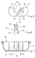
- Figur 7
- einen Längsschnitt durch das Riegelgehäuse.
- Figure 1
- a longitudinal section through an additional bolt lock with inserted bolt bolt;
- Figure 2
- a longitudinal section through the additional bolt lock according to Figure 1 with the bolt bolt pushed out;
- Figure 3
- a section III-III of Figure 2;
- Figure 4
- a view in the direction of arrow IV of Figure 2;
- Figure 5
- a side view of a connecting rod connecting slide;
- Figure 6
- a side view of a bolt bolt; and
- Figure 7
- a longitudinal section through the bolt housing.
Die Figur 1 zeigt einen Längsschnitt durch ein Zusatzriegelschloss,
welches insgesamt mit 10 bezeichnet ist. Ein
derartiges Zusatzriegelschloss 10 ist Teil eines Treibstangenverschlusses
und wird von einem Hauptschloss mittels
einer Treibstange angetrieben. Die nicht dargestellte
Treibstange wird über entsprechende Kupplungen 12 mit einem
Treibstangen-Anschlussschieber 14, welcher im Riegelgehäuse
16 verschieblich gelagert ist, gekuppelt. Dieser Treibstangen-Anschlussschieber
14 liegt mit seiner rückwärtigen
Kante 18 (Figur 5) an der Rückwand 20 des Riegelgehäuses 16
an und stützt sich an dieser ab. Vorteilhaft weist die
Rückwand 20 eine Führungsnut zur Aufnahme des Treibstangen-Anschlussschiebers
14 auf. Der im Wesentlichen U-förmig
gestaltete Treibstangen-Anschlussschieber 14 besitzt
zwischen den beiden Kupplungen 12 einen Steuerschlitz 22,
in welchen ein Führungszapfen 24 eines Bolzenriegels 26
eingreift. Zwischen dem Steuerschlitz 22 und der in der
Zeichnung links dargestellten Kupplung 12 ist eine
Aussparung 28 vorgesehen, welche im Bereich des Steuerschlitzes
22 im Wesentlichen der Form des Steuerschlitzes
22 folgt. Die Aufgabe und Funktion dieser Aussparung 28
wird weiter unten erläutert.FIG. 1 shows a longitudinal section through an additional bolt lock,
which is denoted overall by 10. On
Such
Der Bolzenriegel 26, der in Figur 6 separat dargestellt
ist, weist einen Bolzenkörper 30 und einen Bolzenfuß 32
auf. Der Bolzenfuß 32 besitzt einen im Wesentlichen
rechteckförmigen Querschnitt, wohingegen der Bolzenkörper
30 einen kreisrunden Querschnitt besitzt, was deutlich in
Figur 4 dargestellt ist. In Richtung des freien Endes 34
ist der Bolzenkörper 30 mit einander gegenüberliegenden
Auflaufschrägen 36 versehen und bildet somit einen Keil,
wodurch eine z.B. verzogene Tür herangezogen wird, wenn der
Bolzenriegel 26 aus dem Riegelgehäuse 16 ausgeschoben wird.
Für den Bolzenkörper 30 weist das Riegelgehäuse 16 eine
teilkreisförmige Führungsaufnahme 38 auf, die zwischen zwei
als Führungsleisten 40 ausgebildeten Führungsvorsprüngen 42
vorgesehen ist. Diese Führungsleisten 40 dienen außerdem
zur seitlichen Abstützung des Bolzenfußes 32, der zwischen
diesen beiden Führungsleisten 40 zwischen der eingeschobenen
Stellung und der ausgeschobenen Stellung verschieblich
gelagert ist. Diese Führungsleisten 40 dienen außerdem,
zusammen mit einer Führungsleiste 44, zur Abstützung des
Treibstangen-Anschlussschiebers 14, der zwischen diesen
Führungsleisten 40, 44 und der Innenfläche der benachbarten
Seitenwand des Riegelgehäuses 16 verschieblich gelagert
ist. Weiterhin dienen die Führungsleisten 40, 44 der
Versteifung des Riegelgehäuses 16.The
Aus der Zeichnung ist deutlich erkennbar, dass der
Führungszapfen 24 mit Abstand zur Längsachse 46 des
Bolzenkörpers 30 am Bolzenfuß 32 vorgesehen ist. Diese
seitlich versetzte Ankopplung des Bolzenriegels 26 am
Treibstangen-Anschlussschieber 14 hat zur Folge, dass der
Treibstangen-Anschlussschieber 14 unmittelbar seitlich
neben dem Steuerschlitz 22 mit der Aussparung 28 versehen
sein kann. Diese Aussparung 28 ist erforderlich, da die
Breite des Bolzenkörpers 30, insbesondere dessen Durchmesser,
in die Ebene des Treibstangen-Anschlussschiebers 14
eingreift. Die Aussparung 28 verhindert somit eine
Kollision des Treibstangen-Anschlussschiebers 14 mit dem
Bolzenkörper 30, wenn der Bolzenriegel 26 ins Riegelgehäuse
16 eingezogen wird. Der Bolzenkörper 30 wandert dabei in
die trapezförmige Aussparung 28 hinein.It can be clearly seen from the drawing that the
Der Treibstangen-Anschlussschieber 14 ist außerdem mit
einem Abstützlappen 48 versehen, der in Richtung des
Bolzenfußes 32 absteht. Dieser Abstützlappen 48 ist als
Stanzbiegeteil aus der Ebene des Treibstangen-Anschlussschiebers
14 ausgeklappt. Ist der Bolzenriegel 26, wie in
den Figuren 2 und 3 dargestellt, vollständig aus dem
Riegelgehäuse 16 ausgeschoben, untergreift der Abstützlappen
48 die Unterseite des Bolzenfußes 32 und bildet eine
Rückdrücksicherung für den Bolzenriegel 26. Das Unterschieben
des Abstützlappens 48 unter den Bolzenfuß 32 wird
dadurch ermöglicht, dass der Steuerschlitz 22 in seinem
stulpseitigen Bereich einen in Verschieberichtung des
Treibstangen-Anschlussschiebers 14 verlaufenden Abschnitt
50 besitzt, in welchem der Bolzenriegel 26 nicht mehr
weiter aus dem Riegelgehäuse 16 ausgeschoben wird. Der
Abschnitt 50 bildet zusammen mit dem Führungszapfen 24 die
primäre Rückdrücksicherung für den Bolzenriegel 26. Am
anderen Ende des Steuerschlitzes 22 ist ebenfalls ein in
gleicher Richtung verlaufender Abschnitt 52 vorgesehen, der
verhindert, dass der eingeschobene Bolzenriegel 26 nicht
versehentlich aus dem Riegelgehäuse 16 ausgeschoben wird.The connecting
Aus der Zeichnung ist deutlich erkennbar, dass nach dem
Einsetzen des Führungszapfens 24 in den Steuerschlitz 22
der Bolzenriegel 26 zusammen mit dem Treibstangen-Anschlussschieber
14 durch die stulpseitige Öffnung 54 des
Riegelgehäuses 16 in dieses eingeschoben werden kann und in
diesem dann korrekt gelagert und geführt ist, ohne dass es
hierfür weiterer Bauteile bedarf. Das Schießen der Öffnung
54 und somit die Lagesicherung der Bauteile innerhalb des
Riegelgehäuses 16 ist durch Anschrauben des Riegelgehäuses
16 an der Stulpschiene bewirkt.From the drawing it can be clearly seen that after the
Inserting the
Claims (19)
Applications Claiming Priority (2)
| Application Number | Priority Date | Filing Date | Title |
|---|---|---|---|
| DE20018104U | 2000-10-23 | ||
| DE20018104U DE20018104U1 (en) | 2000-10-23 | 2000-10-23 | Espagnolette lock |
Publications (1)
| Publication Number | Publication Date |
|---|---|
| EP1201855A1 true EP1201855A1 (en) | 2002-05-02 |
Family
ID=7947961
Family Applications (1)
| Application Number | Title | Priority Date | Filing Date |
|---|---|---|---|
| EP01123108A Withdrawn EP1201855A1 (en) | 2000-10-23 | 2001-09-27 | Serrure à Crémone |
Country Status (3)
| Country | Link |
|---|---|
| EP (1) | EP1201855A1 (en) |
| DE (1) | DE20018104U1 (en) |
| PL (1) | PL195038B1 (en) |
Cited By (2)
| Publication number | Priority date | Publication date | Assignee | Title |
|---|---|---|---|---|
| EP1447504A2 (en) * | 2003-02-17 | 2004-08-18 | Fullex Locks Limited | Apparatus for locking a closure |
| FR3111930A1 (en) * | 2020-06-24 | 2021-12-31 | Assa Abloy France Sas | Locking lock with auxiliary bolts |
Citations (5)
| Publication number | Priority date | Publication date | Assignee | Title |
|---|---|---|---|---|
| FR2319760A1 (en) * | 1975-07-28 | 1977-02-25 | Drevet Guy | Double morticed door lock - has barrel lock operating main mortice linked to second door handle mortice |
| FR2435587A1 (en) * | 1978-09-08 | 1980-04-04 | Novobat Sarl | Lockable casement bolt with latch and dead bolts - uses coil spring to drive conrods home when released by lever actuated by bit lock cylinder |
| DE8803839U1 (en) * | 1988-03-22 | 1988-09-22 | Carl Fuhr Gmbh & Co, 5628 Heiligenhaus, De | |
| DE9321445U1 (en) * | 1993-02-12 | 1998-02-26 | Fliether Karl Gmbh & Co | Lock to be used in particular on apartment lock doors, in particular lock which can be actuated by a connecting rod |
| EP0891465A1 (en) * | 1996-04-04 | 1999-01-20 | Ferco International Ferrures Et Serrures De Batiment | Espagnolette or espagnolette lock, particularly of multipoint-type |
-
2000
- 2000-10-23 DE DE20018104U patent/DE20018104U1/en not_active Expired - Lifetime
-
2001
- 2001-09-27 EP EP01123108A patent/EP1201855A1/en not_active Withdrawn
- 2001-10-19 PL PL350217A patent/PL195038B1/en unknown
Patent Citations (5)
| Publication number | Priority date | Publication date | Assignee | Title |
|---|---|---|---|---|
| FR2319760A1 (en) * | 1975-07-28 | 1977-02-25 | Drevet Guy | Double morticed door lock - has barrel lock operating main mortice linked to second door handle mortice |
| FR2435587A1 (en) * | 1978-09-08 | 1980-04-04 | Novobat Sarl | Lockable casement bolt with latch and dead bolts - uses coil spring to drive conrods home when released by lever actuated by bit lock cylinder |
| DE8803839U1 (en) * | 1988-03-22 | 1988-09-22 | Carl Fuhr Gmbh & Co, 5628 Heiligenhaus, De | |
| DE9321445U1 (en) * | 1993-02-12 | 1998-02-26 | Fliether Karl Gmbh & Co | Lock to be used in particular on apartment lock doors, in particular lock which can be actuated by a connecting rod |
| EP0891465A1 (en) * | 1996-04-04 | 1999-01-20 | Ferco International Ferrures Et Serrures De Batiment | Espagnolette or espagnolette lock, particularly of multipoint-type |
Cited By (3)
| Publication number | Priority date | Publication date | Assignee | Title |
|---|---|---|---|---|
| EP1447504A2 (en) * | 2003-02-17 | 2004-08-18 | Fullex Locks Limited | Apparatus for locking a closure |
| EP1447504A3 (en) * | 2003-02-17 | 2006-01-18 | Fullex Locks Limited | Apparatus for locking a closure |
| FR3111930A1 (en) * | 2020-06-24 | 2021-12-31 | Assa Abloy France Sas | Locking lock with auxiliary bolts |
Also Published As
| Publication number | Publication date |
|---|---|
| PL195038B1 (en) | 2007-08-31 |
| DE20018104U1 (en) | 2001-02-22 |
| PL350217A1 (en) | 2002-05-06 |
Similar Documents
| Publication | Publication Date | Title |
|---|---|---|
| EP1066437B1 (en) | Spring-loaded catch for a sliding door of a sheet metal cupboard | |
| EP2059148B1 (en) | Drawer | |
| DE102005048693B4 (en) | Door opener arrangement and adapter piece for use in a door opener arrangement | |
| DE3844849C2 (en) | Espagnolette lock | |
| EP0878576B1 (en) | Door latch device for electric apparatuses | |
| DE3437806C2 (en) | Lock | |
| DE2803346A1 (en) | LOCKING DEVICE FOR A DOOR | |
| EP2312103B1 (en) | Locking device with a strike plate receiving a locking pin bolt | |
| EP0156379B1 (en) | Cash drawer for a cash register | |
| DE60038615T2 (en) | LOCK | |
| EP1318258B1 (en) | Fitting on a wing or a frame of a window, a door or similar | |
| EP1867819B1 (en) | Lock for a connecting rod fitting and connecting rod fitting with such a lock | |
| DE102007025723B3 (en) | Garage door coupling unit, especially for tilting door, enables position of blocking pin and latching position of hook to be cancelled manually and/or by drive motor unit | |
| DE10359803A1 (en) | Espagnolette | |
| EP1201855A1 (en) | Serrure à Crémone | |
| EP1199428A1 (en) | Espagnolette locking device | |
| EP1116841A1 (en) | Lock, in particular mortise lock | |
| EP0298292B1 (en) | Door lock with sliding bolt and latch | |
| DE102004060717B4 (en) | Lock for locking a wing in a frame of a window | |
| DE102016114386A1 (en) | tank latch | |
| DE8330967U1 (en) | QUICK RELEASE DEVICE FOR A LOCKED DOOR | |
| EP0662556B1 (en) | Locking device for a door or a window | |
| DE10357721B4 (en) | Closing device for doors or windows | |
| EP1500764A2 (en) | Latch device | |
| EP0998865A2 (en) | Locking device for drawer slide |
Legal Events
| Date | Code | Title | Description |
|---|---|---|---|
| PUAI | Public reference made under article 153(3) epc to a published international application that has entered the european phase |
Free format text: ORIGINAL CODE: 0009012 |
|
| AK | Designated contracting states |
Kind code of ref document: A1 Designated state(s): AT BE CH CY DE DK ES FI FR GB GR IE IT LI LU MC NL PT SE TR |
|
| AX | Request for extension of the european patent |
Free format text: AL;LT;LV;MK;RO;SI |
|
| 17P | Request for examination filed |
Effective date: 20020625 |
|
| AKX | Designation fees paid |
Free format text: AT BE CH CY DE DK ES FI FR GB GR IE IT LI LU MC NL PT SE TR |
|
| 17Q | First examination report despatched |
Effective date: 20040330 |
|
| GRAP | Despatch of communication of intention to grant a patent |
Free format text: ORIGINAL CODE: EPIDOSNIGR1 |
|
| STAA | Information on the status of an ep patent application or granted ep patent |
Free format text: STATUS: THE APPLICATION IS DEEMED TO BE WITHDRAWN |
|
| 18D | Application deemed to be withdrawn |
Effective date: 20080401 |