EP1200216B1 - Verfahren und einrichtung zum herstellen eines stranges aus metall - Google Patents
Verfahren und einrichtung zum herstellen eines stranges aus metall Download PDFInfo
- Publication number
- EP1200216B1 EP1200216B1 EP00951251A EP00951251A EP1200216B1 EP 1200216 B1 EP1200216 B1 EP 1200216B1 EP 00951251 A EP00951251 A EP 00951251A EP 00951251 A EP00951251 A EP 00951251A EP 1200216 B1 EP1200216 B1 EP 1200216B1
- Authority
- EP
- European Patent Office
- Prior art keywords
- strand
- reduction
- solidification
- cooling
- liquid core
- Prior art date
- Legal status (The legal status is an assumption and is not a legal conclusion. Google has not performed a legal analysis and makes no representation as to the accuracy of the status listed.)
- Expired - Lifetime
Links
- 238000000034 method Methods 0.000 title claims abstract description 18
- 239000002184 metal Substances 0.000 title claims abstract description 6
- 229910052751 metal Inorganic materials 0.000 title claims abstract description 6
- 238000007711 solidification Methods 0.000 claims abstract description 68
- 230000008023 solidification Effects 0.000 claims abstract description 68
- 238000001816 cooling Methods 0.000 claims abstract description 64
- 239000007788 liquid Substances 0.000 claims abstract description 41
- 238000009749 continuous casting Methods 0.000 claims abstract description 5
- 238000009434 installation Methods 0.000 claims abstract 4
- 239000002826 coolant Substances 0.000 claims description 14
- 239000000463 material Substances 0.000 claims description 8
- 238000004519 manufacturing process Methods 0.000 claims description 3
- 230000006978 adaptation Effects 0.000 description 4
- 229910000831 Steel Inorganic materials 0.000 description 3
- 238000005096 rolling process Methods 0.000 description 3
- 239000010959 steel Substances 0.000 description 3
- XEEYBQQBJWHFJM-UHFFFAOYSA-N Iron Chemical compound [Fe] XEEYBQQBJWHFJM-UHFFFAOYSA-N 0.000 description 2
- 238000013528 artificial neural network Methods 0.000 description 2
- 238000005266 casting Methods 0.000 description 2
- 238000009826 distribution Methods 0.000 description 2
- 230000000694 effects Effects 0.000 description 2
- 238000005516 engineering process Methods 0.000 description 2
- 239000011159 matrix material Substances 0.000 description 2
- 230000015556 catabolic process Effects 0.000 description 1
- 239000003795 chemical substances by application Substances 0.000 description 1
- 238000010276 construction Methods 0.000 description 1
- 239000000498 cooling water Substances 0.000 description 1
- 230000002068 genetic effect Effects 0.000 description 1
- 229910052742 iron Inorganic materials 0.000 description 1
- 238000012804 iterative process Methods 0.000 description 1
- 230000007774 longterm Effects 0.000 description 1
- 238000002844 melting Methods 0.000 description 1
- 230000008018 melting Effects 0.000 description 1
- 230000005855 radiation Effects 0.000 description 1
- 239000007921 spray Substances 0.000 description 1
- XLYOFNOQVPJJNP-UHFFFAOYSA-N water Substances O XLYOFNOQVPJJNP-UHFFFAOYSA-N 0.000 description 1
Images

Classifications
-
- B—PERFORMING OPERATIONS; TRANSPORTING
- B22—CASTING; POWDER METALLURGY
- B22D—CASTING OF METALS; CASTING OF OTHER SUBSTANCES BY THE SAME PROCESSES OR DEVICES
- B22D11/00—Continuous casting of metals, i.e. casting in indefinite lengths
- B22D11/12—Accessories for subsequent treating or working cast stock in situ
- B22D11/1206—Accessories for subsequent treating or working cast stock in situ for plastic shaping of strands
-
- B—PERFORMING OPERATIONS; TRANSPORTING
- B21—MECHANICAL METAL-WORKING WITHOUT ESSENTIALLY REMOVING MATERIAL; PUNCHING METAL
- B21B—ROLLING OF METAL
- B21B1/00—Metal-rolling methods or mills for making semi-finished products of solid or profiled cross-section; Sequence of operations in milling trains; Layout of rolling-mill plant, e.g. grouping of stands; Succession of passes or of sectional pass alternations
- B21B1/46—Metal-rolling methods or mills for making semi-finished products of solid or profiled cross-section; Sequence of operations in milling trains; Layout of rolling-mill plant, e.g. grouping of stands; Succession of passes or of sectional pass alternations for rolling metal immediately subsequent to continuous casting
- B21B1/463—Metal-rolling methods or mills for making semi-finished products of solid or profiled cross-section; Sequence of operations in milling trains; Layout of rolling-mill plant, e.g. grouping of stands; Succession of passes or of sectional pass alternations for rolling metal immediately subsequent to continuous casting in a continuous process, i.e. the cast not being cut before rolling
-
- B—PERFORMING OPERATIONS; TRANSPORTING
- B22—CASTING; POWDER METALLURGY
- B22D—CASTING OF METALS; CASTING OF OTHER SUBSTANCES BY THE SAME PROCESSES OR DEVICES
- B22D11/00—Continuous casting of metals, i.e. casting in indefinite lengths
- B22D11/12—Accessories for subsequent treating or working cast stock in situ
- B22D11/128—Accessories for subsequent treating or working cast stock in situ for removing
- B22D11/1282—Vertical casting and curving the cast stock to the horizontal
-
- B—PERFORMING OPERATIONS; TRANSPORTING
- B22—CASTING; POWDER METALLURGY
- B22D—CASTING OF METALS; CASTING OF OTHER SUBSTANCES BY THE SAME PROCESSES OR DEVICES
- B22D11/00—Continuous casting of metals, i.e. casting in indefinite lengths
- B22D11/16—Controlling or regulating processes or operations
- B22D11/22—Controlling or regulating processes or operations for cooling cast stock or mould
- B22D11/225—Controlling or regulating processes or operations for cooling cast stock or mould for secondary cooling
-
- B—PERFORMING OPERATIONS; TRANSPORTING
- B21—MECHANICAL METAL-WORKING WITHOUT ESSENTIALLY REMOVING MATERIAL; PUNCHING METAL
- B21B—ROLLING OF METAL
- B21B2201/00—Special rolling modes
- B21B2201/14—Soft reduction
Definitions
- the invention relates to methods and a device for Production of a strand from metal by means of a continuous caster, the at least one cooling device for cooling of the strand, with the cooling device at least assigned a reduction framework for reducing the thickness of the strand is, the strand solidified when reducing the thickness Has shell and a liquid core.
- the object of the invention is a method and a device to carry out the procedure to indicate which one improved soft reduction compared to the prior art, in particular even with varying strand speeds.
- the object is achieved according to the invention by a method Claim 1 or a device according to claim 10 solved. It is used to manufacture a strand of metal a continuous caster, which has at least one cooling device for cooling the strand, the cooling device at least a reduction framework for reducing the thickness of the strand subordinate, the strand in the thickness reduction a has a solidified shell and a liquid core, and wherein cooling using a temperature and solidification model such, in particular automatically, is set that the Solidification limit between the solidified shell and the liquid Core when the strand enters the reduction frame a predetermined set solidification limit between the solidified Shell and the liquid core corresponds. To this A particularly good soft reduction is achieved in this way.
- Temperature and solidification models can be, for example analytical model, a neural network or a combination be from an analytical model and a neural network.
- the temperature and solidification model advantageously sets cooling the strand and the solidification limit between the solidified shell and the liquid core.
- Such an embodiment of the invention is special Advantage because of the temperature and solidification model the solidification limit between the solidified shell and the liquid core depending on the cooling quantity the cause Effect relationship between cooling and the solidification limit between the solidified shell and the liquid core.
- the Temperature and solidification model the solidification limit between the solidified shell and the liquid core in dependence from cooling the strand, especially in real time and constantly, determined and the necessary cooling of the Strands in an iterative manner depending on the given Target solidification limit between the solidified shell and the liquid core determined, iterating until the Deviation of those determined with the temperature and solidification model Solidification limit between the solidified shell and the liquid core from the predetermined set solidification limit between the solidified shell and the liquid core is less than a predetermined tolerance value.
- to determine the necessary cooling of the strand depending from the specified set solidification limit between the solidified shell and the liquid core at least one further size of the sizes strand speed, strand geometry, Strand shell thickness, mold length, time, strand material, Coolant pressure or volume, droplet size of the coolant and coolant temperature used.
- the sizes strand geometry, strand shell thickness, Time, strand material, coolant pressure or -volume and coolant temperature used is particularly suitable, a particularly precise To achieve cooling of the strand.
- each reduction device a target solidification limit between the solidified shell and the liquid core of the strand assigned.
- the effect of the thickness reduction in the temperature and solidification model through the reduction framework especially the location the boundary between the solidified shell and the liquid core modeled.
- the modeling of the reduction in thickness through the reduction framework by at least one of the quantities reducing power and Degree of reduction.
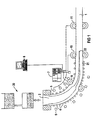
- FIG. 1 shows a continuous caster.
- the cast strand which is a solidified shell 21 within a solidification limit 22 and a liquid Core 2 has.
- the strand is equipped with drive or guide rollers 4 moves and on its way through cooling devices 5 cooled. These are advantageously as water spray devices educated. For the sake of clarity are not all drive or guide rollers 4 and cooling devices 5 provided with reference numerals. In known methods the cooling devices 5 are divided into cooling segments. This division is new and inventive Procedure not necessary, but can be taken into account.
- Both the drive rollers 4 and the cooling devices 5 are technically connected to a computing device. in the The present exemplary embodiment are both in terms of data technology connected to one and the same automation device 7.
- the Automation device 7 optionally also does not have one shown terminal and a keyboard, not shown on.
- a parent Computing system 8 For continuous casting necessary material, in this case liquid steel fed via a feed device 20.
- the manipulated variables for the cooling devices 5 are by means of a temperature and Solidification model, i.e. of a thermal model of the strand calculated that in the exemplary embodiment the superordinate computing system 8 is implemented.
- Reference numerals 9, 10 and 11 denote the cooling device 5 assigned reduction frameworks. These are more advantageous Embodiment of the invention in terms of data technology with the programmable logic controller Controller 7 connected to the automation device 7 the rolling force and the degree of reduction, e.g. in the form of the roll gap.
- Three reduction frames 9, 10 and 11 are exemplary embodiments intended.
- a so-called soft reduction is carried out.
- the strand to be reduced is not soft reduction solidified, but has a liquid core 2 and one solidified shell 21 when it enters a reduction framework.
- the strand 1 only a soft reduction in the reduction frames 9 and 10 are provided.
- Cooling with the cooling devices 5 is set by means of the automation device 7 such that the solidification limit 22 between the solidified shell 21st and the liquid core 2 of the strand 1 when entering the Reduction frameworks 9 and 10 of a desired set solidification limit between the liquid core 2 and the solidified Shell 21 corresponds.
- the reduction framework 9 is particularly advantageous arranged within the cooling section, i.e. there are before and 9 cooling devices 5 are provided behind the reduction frame. In a further advantageous manner, 10 cooling devices also behind the second reduction frame provided.
- the cooling device 9 is advantageously not arranged in the bend of strand 1 like this 1 is indicated for reasons of clarity, but before the bend of the strand or behind the bend of the Stranges 1 arranged.
- the solidification limits e i in the strand are determined in the temperature and solidification model 13 from a given cooling of the strand k i by means of the temperature and solidification model 13.
- This solidification limit e i is compared in a comparator 14 with the set solidification limit e 0 in the strand.
- the comparator 14 asks whether
- the function block 12 determines a new proposal k i for improved cooling of the strand.
- a value for the cooling is used as the initial value for the iteration, which has proven to be a tried-and-tested average over the long term. If the magnitude of the difference between e i and e 0 is less than or equal to the tolerance value ⁇ e max , the setpoint k 0 for cooling the strand is set equal to the value k i with a set cooling setting 15.
- the values e i , e 0 , ⁇ e max , k i , k 0 are not necessarily scalars, but column matrices with one or more values.
- B the column matrix k 0, the various actuating or command variables for the cooling devices 5 of the individual cooling segments 6 of a strand cooling system or the column matrix e 0 , the set solidification limits at different points on the strand.
- the iteration circuit shown in FIG. 2 takes place on the basis of genetic algorithms. This is particularly useful when k i or k 0 are column matrices with many elements.
- the temperature and solidification model 13 can be implemented both as a one-dimensional model and as a two-dimensional model.
- the thermal conduction equation forms the basis of the temperature and solidification model, shown here for the two-dimensional case represents that for the temperature and solidification model 13 in differential form, ie in the form is used.
- T is the temperature
- t is the time
- a is the temperature conductivity.
- x and y are the two-dimensional spatial coordinates.
- the cross section of the strand skin is divided into small rectangles Size ⁇ x times ⁇ y divided and the temperature is in small Time steps ⁇ t calculated.
- the temperature at Entry into the mold in all rectangles
- the manifold temperature of the steel is assumed that the temperature at Entry into the mold (in all rectangles) the manifold temperature of the steel.
- T U equates to the temperature of the cooling water in the mold.
- T U is equated to the temperature of the coolant and ⁇ is, for example, according to calculated, where V is the coolant volume in l / m 2 min. V can be specified differently for each point on the strand surface, which means that the model can also be used to describe nozzle characteristics.
- the solidification limits e i in the strand are determined in the temperature and solidification model 13 from a given cooling of the strand by means of the temperature and solidification model 13.
Landscapes
- Engineering & Computer Science (AREA)
- Mechanical Engineering (AREA)
- Continuous Casting (AREA)
- Treatment Of Steel In Its Molten State (AREA)
- Heat Treatment Of Strip Materials And Filament Materials (AREA)
Description
- FIG 1
- eine Stranggießanlage,
- FIG 2
- ein Ablaufdiagramm zur iterativen Bestimmung einer Soll-Kühlung des Stranges mittels eines Temperatur- und Erstarrungsmodells,
- FIG 3
- ein Ablaufdiagramm zur iterativen Bestimmung eines Adaptionskoeffizienten.



- Kokillenlänge
- Stranggeometrie (Höhe und Breite)
- Stranggeschwindigkeit
- Wärmeübergangskoeffizient α in der Kokille
- Kühlmitteltemperatur in der Kokille
- Schmelztemperatur
- Erstarrungsenthalpie
- Wärmeleitkoeffizient λ
- Spezifische Wärmekapazität c
- Dichte ρ
- Länge jeder Kühlzone
- Kühlmittelvolumen V in jeder Kühlzone
- Strangmaterial
Claims (10)
- Verfahren zum Herstellen eines Stranges (1) aus Metall mittels einer Stranggießanlage, die zumindest eine Kühleinrichtung (5) zur Kühlung des Stranges (1) aufweist, wobei der Kühleinrichtung (5) zumindest ein Reduktionsgerüst (9,10,11) zur Dickenreduktion des Stranges (1) zugeordnet ist, wobei der Strang (1) bei der Dickenreduktion eine erstarrte Hülle (21) und einen flüssigen Kern (2) aufweist,
dadurch gekennzeichnet, daß die Kühlung mittels eines Temperatur- und Erstarrungsmodells (13) derart eingestellt wird, daß die Erstarrungsgrenze (22) zwischen der erstarrten Hülle (21) und dem flüssigen Kern (2) bei Einlauf des Stranges (1) in das Reduktionsgerüst (9,10,11) einer vorgegebenen Soll-Erstarrungsgrenze zwischen der erstarrten Hülle (21) und dem flüssigen Kern (2) entspricht. - Verfahren nach Anspruch 1,
dadurch gekennzeichnet, daß mit dem Temperatur- und Erstarrungsmodell (13) die Erstarrungsgrenze (22) zwischen der erstarrten Hülle (21) und dem flüssigen Kern (2) in Abhängigkeit von der Kühlung des Stranges (1), insbesondere in Echtzeit und ständig, ermittelt wird und daß die notwendige Kühlung des Stranges (1) auf iterative Weise in Abhängigkeit der vorgegebenen Soll-Erstarrungsgrenze (e0) zwischen der erstarrten Hülle (21) und dem flüssigen Kern (2) bestimmt wird, wobei so oft iteriert wird, bis die Abweichung der mit dem Temperatur- und Erstarrungsmodell (13) ermittelten Erstarrungsgrenze (ei) zwischen der erstarrten Hülle (21) und dem flüssigen Kern (2) von der vorgegebenen Soll-Erstarrungsgrenze (ei) zwischen der erstarrten Hülle (21) und dem flüssigen Kern (2) kleiner ist als ein vorgegebener Toleranzwert. - Verfahren nach Anspruch 1 oder 2,
dadurch gekennzeichnet, daß zur Bestimmung der notwendigen Kühlung des Stranges (1) in Abhängigkeit von der vorgegebenen Soll-Erstarrungsgrenze zwischen der erstarrten Hülle (21) und dem flüssigen Kern (2) zumindest eine weitere Größe der Größen Stranggeschwindigkeit, Stranggeometrie, Strangschalendicke, Kokillenlänge, Zeit, Strangmaterial, Kühlmitteldruck bzw. -volumen, Tröpfchengröße des Kühlmittels und Kühlmitteltemperatur verwendet wird. - Verfahren nach Anspruch 1, 2 oder 3,
dadurch gekennzeichnet, daß zur Bestimmung der notwendigen Kühlung des Stranges (1) in Abhängigkeit der Erstarrungsgrenze (22) zwischen der erstarrten Hülle (21) und dem flüssigen Kern (2) auch die Größen Stranggeometrie, Strangschalendicke, Zeit, Strangmaterial, Kühlmitteldruck bzw. -volumen und Kühlmitteltemperatur verwendet werden. - Verfahren nach Anspruch 1, 2, 3 oder 4, wobei der Kühleinrichtung (5) zumindest zwei Reduktionsgerüsten (9,10,11) nachgeordnet sind,
dadurch gekennzeichnet, daß zumindest zwei Reduktionsgerüsten (9,10,11) eine Soll-Erstarrungsgrenze zwischen der erstarrten Hülle (21) und dem flüssigen Kern (2) des Stranges (1) bei Einlauf in das jeweilige Reduktionsgerüst (9,10,11) zugeordnet wird. - Verfahren nach Anspruch 1, 2, 3, 4 oder 5,
dadurch gekennzeichnet, daß im Temperatur- und Erstarrungsmodell (13) die Wirkung der Dickenreduktion durch das Reduktionsgerüst (9,10,11), insbesondere die Lage der Erstarrungsgrenze (22) zwischen erstarrter Hülle (21) und flüssigem Kern (2), mit berücksichtigt wird. - Verfahren nach Anspruch 5,
dadurch gekennzeichnet, daß die Modellierung der Dickenreduktion durch das Reduktionsgerüst (9,10,11) durch zumindest eine der Größen Reduktionskraft und Dickenreduktionsgrad erfolgt. - Verfahren nach einem der vorhergehenden Ansprüche,
dadurch gekennzeichnet, daß zumindest eine der Größen Reduktionskraft und Reduktionsgrad im Reduktionsgerüst (9,10,11) gemessen und zur Adaption des Temperatur- und Erstarrungsmodells (13) verwendet wird. - Verfahren nach Anspruch 8,
dadurch gekennzeichnet, daß die Größen Reduktionskraft und Reduktionsgrad im Reduktionsgerüst (9,10,11) gemessen und zur Adaption des Temperaturund Erstarrungsmodells (13) verwendet werden. - Stranggießanlage zum Herstellen eines Stranges (1), insbesondere nach einem Verfahren gemäß einem der vorhergehenden Ansprüche, wobei die Stranggießanlage zumindest eine Kühleinrichtung (5) zur Kühlung des Stranges (1) und zumindest ein zugeordnetes Reduktionsgerüst (9,10,11) zur Dickenreduktion des Stranges (1) sowie eine Recheneinrichtung zur Steuerung der Kühlung des Stranges mittels der Kühleinrichtung (5) aufweist,
dadurch gekennzeichnet, daß auf der Recheneinrichtung ein Temperatur- und Erstarrungsmodell (13) zur derartigen Einstellung der Erstarrungsgrenze (22) zwischen einer erstarrten Hülle (21) und einem flüssigen Kern (2) des Stranges (1) bei Einlauf des Stranges (1) in das Reduktionsgerüst (9,10,11) implementiert ist, daß die Erstarrungsgrenze (22) einer vorgegebenen Soll-Erstarrungsgrenze zwischen der erstarrten Hülle (21) und dem flüssigen Kern (2) entspricht.
Applications Claiming Priority (3)
| Application Number | Priority Date | Filing Date | Title |
|---|---|---|---|
| DE19931331 | 1999-07-07 | ||
| DE19931331A DE19931331A1 (de) | 1999-07-07 | 1999-07-07 | Verfahren und Einrichtung zum Herstellen eines Stranges aus Metall |
| PCT/DE2000/002117 WO2001003867A1 (de) | 1999-07-07 | 2000-06-29 | Verfahren und einrichtung zum herstellen eines stranges aus metall |
Publications (2)
| Publication Number | Publication Date |
|---|---|
| EP1200216A1 EP1200216A1 (de) | 2002-05-02 |
| EP1200216B1 true EP1200216B1 (de) | 2002-12-11 |
Family
ID=7913934
Family Applications (1)
| Application Number | Title | Priority Date | Filing Date |
|---|---|---|---|
| EP00951251A Expired - Lifetime EP1200216B1 (de) | 1999-07-07 | 2000-06-29 | Verfahren und einrichtung zum herstellen eines stranges aus metall |
Country Status (6)
| Country | Link |
|---|---|
| US (1) | US6880616B1 (de) |
| EP (1) | EP1200216B1 (de) |
| AT (1) | ATE229392T1 (de) |
| DE (2) | DE19931331A1 (de) |
| RU (1) | RU2245214C2 (de) |
| WO (1) | WO2001003867A1 (de) |
Cited By (1)
| Publication number | Priority date | Publication date | Assignee | Title |
|---|---|---|---|---|
| EP2349612B2 (de) † | 2008-11-20 | 2020-11-04 | Primetals Technologies Austria GmbH | Verfahren und stranggiessanlage zum herstellen von dicken brammen |
Families Citing this family (19)
| Publication number | Priority date | Publication date | Assignee | Title |
|---|---|---|---|---|
| AU2002344361A1 (en) * | 2001-06-01 | 2002-12-16 | Sms Demag Aktiengesellschaft | Method for adjusting the dynamic soft reduction of continuous casting systems |
| DE102004002783A1 (de) * | 2004-01-20 | 2005-08-04 | Sms Demag Ag | Verfahren und Einrichtung zum Bestimmen der Lage der Sumpfspitze im Gießstrang beim Stranggießen von flüssigen Metallen, insbesondere von flüssigen Stahlwerkstoffen |
| DE102006056683A1 (de) * | 2006-01-11 | 2007-07-12 | Sms Demag Ag | Verfahren und Vorrichtung zum Stranggießen |
| US20090084517A1 (en) | 2007-05-07 | 2009-04-02 | Thomas Brian G | Cooling control system for continuous casting of metal |
| DE102007058109A1 (de) * | 2007-12-03 | 2009-06-04 | Sms Demag Ag | Vorrichtung zur Steuerung oder Regelung einer Temperatur |
| DE102009010034A1 (de) * | 2009-02-21 | 2010-09-23 | Actech Gmbh | Verfahren und Gießanlage zur gerichteten Erstarrung eines Gusskörpers aus Aluminium oder einer Aluminiumlegierung |
| JP5476959B2 (ja) * | 2009-12-08 | 2014-04-23 | Jfeスチール株式会社 | 軽圧下連続鋳造方法 |
| EP2543454B1 (de) * | 2011-07-08 | 2019-09-04 | Primetals Technologies Germany GmbH | Verfahren und Vorrichtung zur Herstellung von langen Stahlprodukten mit Stranggießen |
| RU2494834C1 (ru) * | 2012-06-27 | 2013-10-10 | Открытое акционерное общество "Магнитогорский металлургический комбинат" | Способ непрерывного литья заготовок |
| RU2564192C1 (ru) * | 2014-04-02 | 2015-09-27 | Открытое акционерное общество "Уральский завод тяжелого машиностроения" | Способ мягкого обжатия непрерывнолитой заготовки |
| US10076783B2 (en) * | 2014-05-14 | 2018-09-18 | Nippon Steel & Sumitomo Metal Corporation | Method for continuous-casting slab |
| AT519277A1 (de) * | 2016-11-03 | 2018-05-15 | Primetals Technologies Austria GmbH | Gieß-Walz-Verbundanlage |
| EP3338914A1 (de) | 2016-12-22 | 2018-06-27 | Primetals Technologies Austria GmbH | Verfahren zur endlosen herstellung eines aufgewickelten warmbands in einer giess-walz-verbundanlage, verfahren zum anfahren einer giess-walz-verbundanlage und giess-walz-verbundanlage |
| DE102017213842A1 (de) * | 2017-08-08 | 2019-02-14 | Sms Group Gmbh | Verfahren und Anlage zum Stranggießen eines metallischen Produkts |
| DE102018216529A1 (de) * | 2018-09-27 | 2020-04-02 | Sms Group Gmbh | Verfahren und Anlage zum Stranggießen eines metallischen Produkts |
| CN109500371A (zh) * | 2018-12-20 | 2019-03-22 | 南京钢铁股份有限公司 | 一种板坯动态二冷和轻压下控制系统 |
| CN110508765A (zh) * | 2019-09-09 | 2019-11-29 | 东北大学 | 一种有利于消除芯部缺陷的大方坯连铸制造方法 |
| CN111360221B (zh) * | 2020-04-03 | 2021-05-25 | 中天钢铁集团有限公司 | 280mm×320mm断面高碳钢消除中心缩孔及控制中心偏析的方法 |
| CN113695548B (zh) * | 2021-08-26 | 2023-01-31 | 宝武杰富意特殊钢有限公司 | 一种连铸小方坯的生产工艺及连铸小方坯 |
Family Cites Families (9)
| Publication number | Priority date | Publication date | Assignee | Title |
|---|---|---|---|---|
| JPS5422777B2 (de) | 1973-09-17 | 1979-08-09 | ||
| DE3818077A1 (de) * | 1988-05-25 | 1989-11-30 | Mannesmann Ag | Verfahren zum kontinuierlichen giesswalzen |
| US5488987A (en) * | 1991-10-31 | 1996-02-06 | Danieli & C. Officine Meccaniche Spa | Method for the controlled pre-rolling of thin slabs leaving a continuous casting plant, and relative device |
| RU2044598C1 (ru) * | 1992-10-19 | 1995-09-27 | Акционерное общество "Носта" | Способ производства непрерывнолитой заготовки |
| AT408197B (de) * | 1993-05-24 | 2001-09-25 | Voest Alpine Ind Anlagen | Verfahren zum stranggiessen eines metallstranges |
| DE19508476A1 (de) * | 1995-03-09 | 1996-09-12 | Siemens Ag | Leitsystem für eine Anlage der Grundstoff- oder der verarbeitenden Industrie o. ä. |
| US5734329A (en) | 1995-07-13 | 1998-03-31 | Dell Usa L.P. | Method and apparatus for superimposing self-clocking multifunctional communications on a static digital signal line |
| AT410875B (de) | 1996-01-10 | 2003-08-25 | Frequentis Nachrichtentechnik Gmbh | Verfahren und anlage zur übertragung von daten |
| DE19612420C2 (de) * | 1996-03-28 | 2000-06-29 | Siemens Ag | Verfahren und Einrichtung zur Steuerung der Kühlung eines Stranges in einer Stranggießanlage |
-
1999
- 1999-07-07 DE DE19931331A patent/DE19931331A1/de not_active Ceased
-
2000
- 2000-06-29 EP EP00951251A patent/EP1200216B1/de not_active Expired - Lifetime
- 2000-06-29 RU RU2002103039/02A patent/RU2245214C2/ru not_active IP Right Cessation
- 2000-06-29 US US10/030,340 patent/US6880616B1/en not_active Expired - Lifetime
- 2000-06-29 AT AT00951251T patent/ATE229392T1/de active
- 2000-06-29 WO PCT/DE2000/002117 patent/WO2001003867A1/de not_active Ceased
- 2000-06-29 DE DE50000941T patent/DE50000941D1/de not_active Expired - Lifetime
Cited By (1)
| Publication number | Priority date | Publication date | Assignee | Title |
|---|---|---|---|---|
| EP2349612B2 (de) † | 2008-11-20 | 2020-11-04 | Primetals Technologies Austria GmbH | Verfahren und stranggiessanlage zum herstellen von dicken brammen |
Also Published As
| Publication number | Publication date |
|---|---|
| WO2001003867A1 (de) | 2001-01-18 |
| EP1200216A1 (de) | 2002-05-02 |
| US6880616B1 (en) | 2005-04-19 |
| RU2245214C2 (ru) | 2005-01-27 |
| DE19931331A1 (de) | 2001-01-18 |
| DE50000941D1 (de) | 2003-01-23 |
| ATE229392T1 (de) | 2002-12-15 |
Similar Documents
| Publication | Publication Date | Title |
|---|---|---|
| DE19612420C2 (de) | Verfahren und Einrichtung zur Steuerung der Kühlung eines Stranges in einer Stranggießanlage | |
| EP1200216A1 (de) | Verfahren und einrichtung zum herstellen eines stranges aus metall | |
| EP0813701B1 (de) | Leitsystem für eine anlage der grundstoff- oder der verarbeitenden industrie o.ä. | |
| EP3184202B1 (de) | Verfahren zum stranggiessen eines metallstranges | |
| DE2252722A1 (de) | Verfahren und vorrichtung zum direkten kuehlen einer kontinuierlich gewalzten stange | |
| EP2346631B1 (de) | Verfahren und vorrichtung zur steuerung der erstarrung eines giessstranges in einer stranggiessanlage beim anfahren des giessprozesses | |
| EP2279052B1 (de) | Verfahren zum stranggiessen eines metallstrangs | |
| AT408197B (de) | Verfahren zum stranggiessen eines metallstranges | |
| EP2279053B1 (de) | Verfahren zum stranggiessen eines metallstrangs | |
| EP0732979B1 (de) | Giess-walzanlage für stahlbänder und regelsystem dafür | |
| AT411026B (de) | Verfahren zum stranggiessen | |
| EP3733323B1 (de) | Verfahren und stranggiessanlage zum giessen eines giessstrangs | |
| WO2004080628A1 (de) | Giesswalzanlage zum erzeugen eines stahlbandes | |
| DE102020209794A1 (de) | Verfahren zur Steuerung oder Regelung der Temperatur eines Gießstrangs in einer Stranggießanlage | |
| WO2004048016A2 (de) | Verfahren und einrichtung zum stranggiessen von brammen-dünnbrammen-, vorbloco-, vorprofil-, knüppelsträngen und dgl. aus flüssigem metall, insbesondere aus stahlwerkstoff | |
| DE102009048567B4 (de) | Verfahren und Anordnung zum Kühlen eines Gießstrangs in einer Stranggießanlage | |
| DE3440235C2 (de) | Verfahren und Vorrichtung zum Bandstranggießen von Metallen, insbesondere von Stahl | |
| AT518450B1 (de) | Verfahren und Kühleinrichtung zum Kühlen eines metallischen Strangs | |
| DE69000282T2 (de) | Verfahren und vorrichtung zur herstellung von duennen metallprodukten mittels strangguss. | |
| EP3744440A1 (de) | Verfahren und vorrichtung zum stranggiessen | |
| WO2013127982A1 (de) | Modellierung einer giesswalzanlage | |
| AT403351B (de) | Verfahren zum stranggiessen eines metallstranges | |
| EP2480356A1 (de) | Verfahren und vorrichtung zum vergiessen von metallischer schmelze in einer stranggiessmaschine | |
| EP3944910A1 (de) | Verfahren zur herstellung eines giessstrangs in einer stranggiessanlage | |
| WO2020177937A1 (de) | Verfahren zur herstellung eines metallischen bandes oder blechs |
Legal Events
| Date | Code | Title | Description |
|---|---|---|---|
| PUAI | Public reference made under article 153(3) epc to a published international application that has entered the european phase |
Free format text: ORIGINAL CODE: 0009012 |
|
| 17P | Request for examination filed |
Effective date: 20011203 |
|
| AK | Designated contracting states |
Kind code of ref document: A1 Designated state(s): AT BE CH CY DE DK ES FI FR GB GR IE IT LI LU MC NL PT SE |
|
| GRAG | Despatch of communication of intention to grant |
Free format text: ORIGINAL CODE: EPIDOS AGRA |
|
| GRAG | Despatch of communication of intention to grant |
Free format text: ORIGINAL CODE: EPIDOS AGRA |
|
| GRAH | Despatch of communication of intention to grant a patent |
Free format text: ORIGINAL CODE: EPIDOS IGRA |
|
| 17Q | First examination report despatched |
Effective date: 20020618 |
|
| GRAH | Despatch of communication of intention to grant a patent |
Free format text: ORIGINAL CODE: EPIDOS IGRA |
|
| GRAA | (expected) grant |
Free format text: ORIGINAL CODE: 0009210 |
|
| AK | Designated contracting states |
Kind code of ref document: B1 Designated state(s): AT BE DE FI GB IT |
|
| REF | Corresponds to: |
Ref document number: 229392 Country of ref document: AT Date of ref document: 20021215 Kind code of ref document: T |
|
| REG | Reference to a national code |
Ref country code: GB Ref legal event code: FG4D Free format text: NOT ENGLISH |
|
| REG | Reference to a national code |
Ref country code: IE Ref legal event code: FG4D Free format text: GERMAN |
|
| REF | Corresponds to: |
Ref document number: 50000941 Country of ref document: DE Date of ref document: 20030123 |
|
| GBT | Gb: translation of ep patent filed (gb section 77(6)(a)/1977) |
Effective date: 20030315 |
|
| REG | Reference to a national code |
Ref country code: IE Ref legal event code: FD4D Ref document number: 1200216E Country of ref document: IE |
|
| PLBQ | Unpublished change to opponent data |
Free format text: ORIGINAL CODE: EPIDOS OPPO |
|
| PLBI | Opposition filed |
Free format text: ORIGINAL CODE: 0009260 |
|
| PLAX | Notice of opposition and request to file observation + time limit sent |
Free format text: ORIGINAL CODE: EPIDOSNOBS2 |
|
| 26 | Opposition filed |
Opponent name: SMS DEMAG AG Effective date: 20030908 |
|
| PLAX | Notice of opposition and request to file observation + time limit sent |
Free format text: ORIGINAL CODE: EPIDOSNOBS2 |
|
| PLBB | Reply of patent proprietor to notice(s) of opposition received |
Free format text: ORIGINAL CODE: EPIDOSNOBS3 |
|
| APBP | Date of receipt of notice of appeal recorded |
Free format text: ORIGINAL CODE: EPIDOSNNOA2O |
|
| APAH | Appeal reference modified |
Free format text: ORIGINAL CODE: EPIDOSCREFNO |
|
| APBQ | Date of receipt of statement of grounds of appeal recorded |
Free format text: ORIGINAL CODE: EPIDOSNNOA3O |
|
| APBU | Appeal procedure closed |
Free format text: ORIGINAL CODE: EPIDOSNNOA9O |
|
| PLCK | Communication despatched that opposition was rejected |
Free format text: ORIGINAL CODE: EPIDOSNREJ1 |
|
| PLBN | Opposition rejected |
Free format text: ORIGINAL CODE: 0009273 |
|
| STAA | Information on the status of an ep patent application or granted ep patent |
Free format text: STATUS: OPPOSITION REJECTED |
|
| 27O | Opposition rejected |
Effective date: 20080214 |
|
| PGFP | Annual fee paid to national office [announced via postgrant information from national office to epo] |
Ref country code: GB Payment date: 20120618 Year of fee payment: 13 |
|
| PGFP | Annual fee paid to national office [announced via postgrant information from national office to epo] |
Ref country code: IT Payment date: 20120626 Year of fee payment: 13 |
|
| PGFP | Annual fee paid to national office [announced via postgrant information from national office to epo] |
Ref country code: FI Payment date: 20130613 Year of fee payment: 14 |
|
| REG | Reference to a national code |
Ref country code: DE Ref legal event code: R084 Ref document number: 50000941 Country of ref document: DE Effective date: 20130814 |
|
| PGFP | Annual fee paid to national office [announced via postgrant information from national office to epo] |
Ref country code: BE Payment date: 20130710 Year of fee payment: 14 |
|
| REG | Reference to a national code |
Ref country code: DE Ref legal event code: R085 Ref document number: 50000941 Country of ref document: DE |
|
| GBPC | Gb: european patent ceased through non-payment of renewal fee |
Effective date: 20130629 |
|
| REG | Reference to a national code |
Ref country code: DE Ref legal event code: R085 Ref document number: 50000941 Country of ref document: DE Effective date: 20140214 |
|
| PG25 | Lapsed in a contracting state [announced via postgrant information from national office to epo] |
Ref country code: GB Free format text: LAPSE BECAUSE OF NON-PAYMENT OF DUE FEES Effective date: 20130629 |
|
| PG25 | Lapsed in a contracting state [announced via postgrant information from national office to epo] |
Ref country code: IT Free format text: LAPSE BECAUSE OF NON-PAYMENT OF DUE FEES Effective date: 20130629 |
|
| PG25 | Lapsed in a contracting state [announced via postgrant information from national office to epo] |
Ref country code: FI Free format text: LAPSE BECAUSE OF NON-PAYMENT OF DUE FEES Effective date: 20140629 |
|
| REG | Reference to a national code |
Ref country code: DE Ref legal event code: R081 Ref document number: 50000941 Country of ref document: DE Owner name: PRIMETALS TECHNOLOGIES GERMANY GMBH, DE Free format text: FORMER OWNER: SIEMENS AKTIENGESELLSCHAFT, 80333 MUENCHEN, DE |
|
| REG | Reference to a national code |
Ref country code: AT Ref legal event code: PC Ref document number: 229392 Country of ref document: AT Kind code of ref document: T Owner name: PRIMETALS TECHNOLOGIES GERMANY GMBH, DE Effective date: 20170227 |
|
| PG25 | Lapsed in a contracting state [announced via postgrant information from national office to epo] |
Ref country code: BE Free format text: LAPSE BECAUSE OF NON-PAYMENT OF DUE FEES Effective date: 20140630 |
|
| PGFP | Annual fee paid to national office [announced via postgrant information from national office to epo] |
Ref country code: AT Payment date: 20170622 Year of fee payment: 18 |
|
| REG | Reference to a national code |
Ref country code: AT Ref legal event code: MM01 Ref document number: 229392 Country of ref document: AT Kind code of ref document: T Effective date: 20180629 |
|
| PG25 | Lapsed in a contracting state [announced via postgrant information from national office to epo] |
Ref country code: AT Free format text: LAPSE BECAUSE OF NON-PAYMENT OF DUE FEES Effective date: 20180629 |
|
| PGFP | Annual fee paid to national office [announced via postgrant information from national office to epo] |
Ref country code: DE Payment date: 20190619 Year of fee payment: 20 |
|
| REG | Reference to a national code |
Ref country code: DE Ref legal event code: R071 Ref document number: 50000941 Country of ref document: DE |
|
| REG | Reference to a national code |
Ref country code: DE Ref legal event code: R081 Ref document number: 50000941 Country of ref document: DE Owner name: PRIMETALS TECHNOLOGIES GERMANY GMBH, DE Free format text: FORMER OWNER: PRIMETALS TECHNOLOGIES GERMANY GMBH, 91052 ERLANGEN, DE |