EP1199543A1 - Verfahren und Vorrichtung zur Planheitsermittlung - Google Patents
Verfahren und Vorrichtung zur Planheitsermittlung Download PDFInfo
- Publication number
- EP1199543A1 EP1199543A1 EP01402728A EP01402728A EP1199543A1 EP 1199543 A1 EP1199543 A1 EP 1199543A1 EP 01402728 A EP01402728 A EP 01402728A EP 01402728 A EP01402728 A EP 01402728A EP 1199543 A1 EP1199543 A1 EP 1199543A1
- Authority
- EP
- European Patent Office
- Prior art keywords
- roller
- strip
- sector
- temperature
- cooling
- Prior art date
- Legal status (The legal status is an assumption and is not a legal conclusion. Google has not performed a legal analysis and makes no representation as to the accuracy of the status listed.)
- Granted
Links
Images

Classifications
-
- B—PERFORMING OPERATIONS; TRANSPORTING
- B21—MECHANICAL METAL-WORKING WITHOUT ESSENTIALLY REMOVING MATERIAL; PUNCHING METAL
- B21B—ROLLING OF METAL
- B21B38/00—Methods or devices for measuring, detecting or monitoring specially adapted for metal-rolling mills, e.g. position detection, inspection of the product
- B21B38/02—Methods or devices for measuring, detecting or monitoring specially adapted for metal-rolling mills, e.g. position detection, inspection of the product for measuring flatness or profile of strips
-
- G—PHYSICS
- G01—MEASURING; TESTING
- G01B—MEASURING LENGTH, THICKNESS OR SIMILAR LINEAR DIMENSIONS; MEASURING ANGLES; MEASURING AREAS; MEASURING IRREGULARITIES OF SURFACES OR CONTOURS
- G01B7/00—Measuring arrangements characterised by the use of electric or magnetic techniques
- G01B7/34—Measuring arrangements characterised by the use of electric or magnetic techniques for measuring roughness or irregularity of surfaces
-
- G—PHYSICS
- G01—MEASURING; TESTING
- G01B—MEASURING LENGTH, THICKNESS OR SIMILAR LINEAR DIMENSIONS; MEASURING ANGLES; MEASURING AREAS; MEASURING IRREGULARITIES OF SURFACES OR CONTOURS
- G01B21/00—Measuring arrangements or details thereof, where the measuring technique is not covered by the other groups of this subclass, unspecified or not relevant
- G01B21/30—Measuring arrangements or details thereof, where the measuring technique is not covered by the other groups of this subclass, unspecified or not relevant for measuring roughness or irregularity of surfaces
-
- G—PHYSICS
- G01—MEASURING; TESTING
- G01B—MEASURING LENGTH, THICKNESS OR SIMILAR LINEAR DIMENSIONS; MEASURING ANGLES; MEASURING AREAS; MEASURING IRREGULARITIES OF SURFACES OR CONTOURS
- G01B5/00—Measuring arrangements characterised by the use of mechanical techniques
- G01B5/28—Measuring arrangements characterised by the use of mechanical techniques for measuring roughness or irregularity of surfaces
- G01B5/285—Measuring arrangements characterised by the use of mechanical techniques for measuring roughness or irregularity of surfaces for controlling eveness
-
- B—PERFORMING OPERATIONS; TRANSPORTING
- B21—MECHANICAL METAL-WORKING WITHOUT ESSENTIALLY REMOVING MATERIAL; PUNCHING METAL
- B21B—ROLLING OF METAL
- B21B1/00—Metal-rolling methods or mills for making semi-finished products of solid or profiled cross-section; Sequence of operations in milling trains; Layout of rolling-mill plant, e.g. grouping of stands; Succession of passes or of sectional pass alternations
- B21B1/22—Metal-rolling methods or mills for making semi-finished products of solid or profiled cross-section; Sequence of operations in milling trains; Layout of rolling-mill plant, e.g. grouping of stands; Succession of passes or of sectional pass alternations for rolling plates, strips, bands or sheets of indefinite length
- B21B1/24—Metal-rolling methods or mills for making semi-finished products of solid or profiled cross-section; Sequence of operations in milling trains; Layout of rolling-mill plant, e.g. grouping of stands; Succession of passes or of sectional pass alternations for rolling plates, strips, bands or sheets of indefinite length in a continuous or semi-continuous process
- B21B1/26—Metal-rolling methods or mills for making semi-finished products of solid or profiled cross-section; Sequence of operations in milling trains; Layout of rolling-mill plant, e.g. grouping of stands; Succession of passes or of sectional pass alternations for rolling plates, strips, bands or sheets of indefinite length in a continuous or semi-continuous process by hot-rolling, e.g. Steckel hot mill
Definitions
- the subject of the invention is a method and a device for detecting flatness of a metal strip product moving in one direction longitudinal and applies especially to bands located at a high temperature.
- a support cylinder comprising a deformable envelope rotatably mounted around a fixed shaft and supported on it by a plurality of jacks spread across the width of the band and which can be adjusted in position and pressure.
- These adjustment means are controlled from the information data by a measuring device, placed downstream of the rolling mill, and sensitive to variations, over the width of the strip, of the tensile force applied to these which themselves correspond to the variations in elongation of the longitudinal fibers of the strip.
- Such a measuring device usually consists of a roller deflector comprising a cylindrical body mounted to rotate about an axis perpendicular to the longitudinal direction of travel of the strip. This one is applied under tension to an angular sector of the external face of the roller which is equipped with a series of sensors to measure the variations in the local application pressure of the strip.
- these detectors are regularly separated from each other and spread over the whole the length of the roll, the strip being thus divided into a series of zones longitudinal each having a determined width, on which we integrates the measurement of the latent fault to be corrected.
- the deflector roller comprises a tubular central body of sufficient thickness to give the necessary resistance and provided, on its external face, of a plurality of housings in which are placed measurement sensors.
- a measuring roller comprises a plurality of detection zones distributed over its entire length and each provided with a sensor for the emission of a signal depending on the application pressure of the corresponding part of the strip, when passing this zone of detection in the angular sector of contact of the strip with the roller.
- the sensors are advantageously angularly offset from one zone to the next.
- each measurement sensor is sensitive to the tape application pressure but can also be influenced by other factors which may disturb the measurement.
- each sensor housing is closed, towards the outside, by a protective wall which may consist of a thin envelope covering the entire tubular body of the roller or else a cap-shaped piece that deforms slightly to transmit to the sensors the pressure applied by the strip.
- a protective wall which may consist of a thin envelope covering the entire tubular body of the roller or else a cap-shaped piece that deforms slightly to transmit to the sensors the pressure applied by the strip.
- measurement sensors are not provided, normally to operate at a high temperature.
- the hot strip is at a high temperature and results from disturbances in the measurements which must be compensated.
- the object of the invention is to solve these problems by means of particularly simple provisions which can apply to all types of flatness measuring rollers which avoid calibration of the sensors according to the different operating temperatures.
- the invention therefore generally applies to a method and a device for detecting the flatness of a strip product in which the strip is tensioned and applied to an angular sector of a measuring roller mounted to rotate about an axis perpendicular to the direction longitudinal travel of the strip and having a cylindrical external face comprising an angular sector of contact with the strip and a free sector.
- a forced cooling of the roller by circulation of a heat transfer fluid along at least part of the free sector of the external face of the roller and the parameters are determined determining cooling efficiency such as opening up the sector cooling angle along which the fluid circulates, the temperature initial of it and the traffic flow, so that after getting heated when passing through the contact area with the strip, the face external of the roller is brought back, by its passage in the sector of cooling of the roller to a determined equilibrium temperature.
- a first particularly advantageous embodiment performs forced cooling of the roller by spraying a fluid coolant by means of spray bars distributed over at least one part of the free sector of the roller and at least the temperature of the fluid and the spraying rate as a function of the temperature of the strip, the running speed and heat exchange conditions, so that reduce the temperature of the external face of the roller to a determined level immediately before passing through the contact area.
- the external face of the latter comprises a lower part which plunges into a bath of heat transfer liquid formed in a bowl placed below the roller and associated with placing means circulating liquid with adjustable flow between an inlet and a outlet of the bowl, and at least the initial temperature of the liquid on arrival in the bath and the circulation rate, so as to bring at a certain level the temperature of the external face of the roller immediately before passing through the contact area.
- the outer face of the roller is brought back, before it passes through the contact zone, to an equilibrium temperature t which is linked to the temperature of the strip t 1 and to the initial temperature t 2 of the heat transfer fluid.
- t at AT t 1 + b B t 2 at AT + b B in which a is the heat exchange coefficient between the strip and the roller, b is the heat exchange coefficient between the heat transfer fluid and the roller, A the angular contact sector and B the angular cooling sector.
- the invention also covers a flatness detection device for the implementation of the method, comprising a forced cooling means of the external face of the measuring roller by circulation of a heat transfer fluid along at least part of the free sector of the roller and the means of adjustment of the cooling conditions to maintain the external face of the roller at a determined equilibrium temperature, with cooling controlled each detection zone during its passage in the sector free from the roller.
- the invention applies especially to rolls for measuring flatness of the type comprising a plurality of detection zones distributed over the length of the roll and each equipped with a sensor for the emission of a signal depending on the application pressure of a corresponding part of the strip, during the passage of said detection zone in the sector angular contact of the strip with the roller, said detection zones being brought to the same equilibrium temperature at each passage in the free sector of the roller.
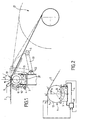
- Figure 1 is a schematic view, in cross section, of a flatness measuring device according to the invention, with winding below of the scroll plan.
- Figure 2 is a diagram of the cooling system of a roller.
- Figure 3 shows, in side view, another embodiment of the invention, with winding above the travel plane.
- FIG. 4 is a top view of the roller of FIG. 3.
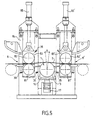
- Figure 5 is a schematic view, in cross section, of another embodiment of the invention.
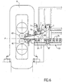
- FIG. 6 shows another embodiment of the invention, in another application.
- Figure 1 there is shown schematically, the mounting of a flatness measuring roller 1 to which a tape is applied metallic 2 which runs in a longitudinal direction parallel to the plane of the figure and is wound on a winder 21 which, in this example, is placed below the plan P of travel of the strip.
- the winding of the tape is carried out under traction, the winder 21 being provided, for this purpose, with known means which need not be described.
- the strip 2 is deflected by the roller 1 and applied to a sector angular of it, under a longitudinal tension determined by the winding control means.
- the flatness measuring roller 1 can be of any known type, for example example, the one described in French patent N ° 2,468,878 of the same society.
- a flatness roller comprises a tubular body 11 in which are housed housings 12 which are closed by a thin envelope 13 threaded onto the tubular body 11.
- a detection device by example a displacement probe 14 which comprises a fixed element taking support on the bottom of the housing 12 and a movable element bearing on the inner face of the casing 13 closing the housing 12 outwards.
- the roller 11 is rotatably mounted around its axis 10 and it is equipped a number of detectors 12, 14 distributed over its entire length so as to cover the width of the strip M applied to the roll 1.
- the measuring roller 1 can be placed downstream, in the direction of scrolling, of a hot rolling installation not shown in the Fig.
- the temperature of the hot strip arriving on the roller 1 can be, for example, between 250 ° C and 400 ° C in the case of a metal not ferrous but it could be higher. This results in overheating important of the roller by its external face.
- the outer face of the roller 1 is covered by the strip 2 only on an angular sector a, a 'relatively reduced whose angle at the center A does not normally exceed 20 ° and therefore includes a free sector a ', between 340 and 350 °.
- the invention takes advantage of this arrangement by performing forced cooling of the face external 13 of the roller by circulation of a heat transfer fluid along at least part of this free sector a, a 'and by determining the conditions of cooling so as to bring each detection zone to the same equilibrium temperature during its passage in the free sector.
- the roller 1 is placed below the strip and it is possible to immerse the lower part of the free sector in a tank 3 filled with a heat transfer liquid 31 such as water.
- This tray 3 is wide open at the top so that the lower part of the roller is submerged over a relatively large angular sector B, by example, of the order of 90 to 110 °.
- each part 15 of the envelope 13 closing a housing 12 constitutes a detection zone which heats up first in contact with strip 2 passing through the angular sector A but is immediately cooled in contact with water 31 passing through the sector b, b 'of angle at the center B.
- the tank 3 is connected to a circuit 4 for circulating the cooling fluid 31 between an inlet and an outlet, comprising means 41 for adjusting the cooling parameters such as the initial temperature and the circulation rate of the fluid 31 as a function of the temperature t 1 of the strip, so as to bring the outer face 13 of the roller to a determined temperature t 3 .
- each detection zone is therefore brought back at a constant temperature level before returning to the area angular A in contact with the strip 2. This ensures the repeatability of the measurement of the pressure applied by the strip to the wall 15 or of the displacement thereof since the thermal influence of the strip is exerted always the same way.
- the tape running speed may vary, for example depending on the thickness reduction carried out in the rolling mill.
- the strip 2 remains applied to the same part of the roller and this results in a temperature rise which could damage the sensors.
- the measuring roller 1 which serves as a deflector roller is then placed, also, above band 2 and it must be associated with a device for cooling placed on the side.
- This cooling device is then consisting of a box 30 having two longitudinal walls 33, 34 parallel to the axis 10 of the roller and extending to an edge 33 ', 34', placed close the outer face 13 of the roller.
- the ends 33 ', 34' are angularly separated so as to limit a cooling sector angle at center B at least equal to a quadrant.
- the box 30 Inside the box 30 is placed at least one spray bar fluid consisting of a pipe 35 connected to a circuit 36 for supplying a heat transfer fluid and provided with a plurality of orifices forming nozzles spray 37 of the fluid directed towards the external face 13 of the roller so the fluid jets are substantially contiguous and cover a sector angle of the roller, over the entire length thereof.
- the box 30 is provided with two spray bars 35 whose nozzles 37 are angularly and longitudinally offset so as to better distribute the fluid over the entire angular sector B.
- the circuit supply 36 is associated with a means 36 'for adjusting the flow sprayed in function of the temperature of the strip 2 to maintain the external face 13 of the roller 1 at a determined temperature, in front of application sector A.
- this is associated with a deflector roller 5 mounted at the end of a pair of arms 51 which can pivot around an axis 52 between a raised position for which the strip 2 is applied to the winder 21 and a position lowered for which the strip 2 is deflected by the roller 5 and is slightly away from the outside of the roller 1.
- the strip laminate is at a much higher temperature which can range, for example example from 700 to 1000 ° C, and must undergo a first cooling before to be wound into a reel.
- a cooling bench must then be interposed between the rolling mill and the winder which is therefore placed at a fairly large distance from the rolling mill.
- this first cooling is not homogeneous across the width of the strip and may cause uneven fiber shortening, variations in elongation due to rolling mill found only after complete cooling of the strip wound in a reel. If the measuring roller is placed just before the winding, at the outlet of the cooling bench, the measurement of the elongation distribution therefore risks being distorted.
- the measuring roller flatness 1 can be placed between two pairs of pinch rollers 8, 8 ' each comprising a fixed roller 81 and a movable roller 82 mounted on a support 83 sliding vertically between two guides of a frame 84, under the action of a jack 85.
- the flatness roller 1 is itself carried by a support cradle 16 mounted to slide vertically under the action of a jack 17.
- the strip In the lowered position of the rollers 82, 82 ', the strip is pinched between the two pairs of rollers 8, 8 'and the jack 17 for lifting the cradle support 16 allows the relative level of the measuring roller 1 to be adjusted by relative to the running plane of the strip and thus determine an angle A applying tape 2 to roller 1.
- At least one of the pinch rollers of each pair 8, 8 ' is rotated at a speed which can be adjusted separately on each pair 8, 8 '.
- Spray bars 35 arranged on either side of the roller 1 allow forced cooling of the free sector thereof.
- the flatness measurement of a hot strip could be useful in the case of a so-called "mini-mill” installation comprising a casting continuous in thin strip followed by some in-line finishing cages, a cooling bench and a winder.
- FIG. 6 which shows, by way of example, an arrangement of this type, only the last finishing cage 6 has been shown.
- the moving strip from left to right in the figure along a horizontal rolling plane P passes first between the two working rolls 60 of the cage 6 then on a cooling bench 23 comprising a support table consisting of a series of rollers 24 tangent to the travel plane P, as well as means which are not shown in the figure.
- the roller 1 for measuring flatness is mounted at the exit of the rolling mill but the strip can be put under tension by the winder placed at the end of the line. We admit, in fact, not to check the flatness on the tape head whose length is negligible when the strip is continuously cast.
- this is mounted on a support cradle 7 which can pivot, about an axis 70, on two aligned bearings fixed, for example, on the rolling stand 6.
- a jack 71 controls the pivoting of the roller 1 between a raised position shown in solid lines in FIG. 5 and a position lowered for which the roller 1 'is interposed between two rollers 25, 25 'of the roller table 23 and therefore determines the application on the measuring roller 1, of the strip 2 which, in this case, is energized by the winder placed at the end of the cooling bench 23 and not shown in the figure.
- the tensile force applied to the web by the winder can be adjusted according to the rolling speed between the working rolls 60, so as to make a winding with contiguous turns.
- the opening of the angular sector of application of the strip depends on the level of the lowered position 1 ′ of the roller 1 relative to the plane of the rollers 25, 25 ', which can be adjusted by means of the jack 71.
- the measuring roller 1 is associated to a cooling box 34 fixed on the cradle 7 and provided with a ramp 35 spraying a coolant on part of the free sector of the roller.
Landscapes
- Physics & Mathematics (AREA)
- General Physics & Mathematics (AREA)
- Engineering & Computer Science (AREA)
- Mechanical Engineering (AREA)
- Force Measurement Appropriate To Specific Purposes (AREA)
- Length Measuring Devices With Unspecified Measuring Means (AREA)
- Burglar Alarm Systems (AREA)
- Electrical Discharge Machining, Electrochemical Machining, And Combined Machining (AREA)
- Finish Polishing, Edge Sharpening, And Grinding By Specific Grinding Devices (AREA)
- Length Measuring Devices By Optical Means (AREA)
Applications Claiming Priority (2)
| Application Number | Priority Date | Filing Date | Title |
|---|---|---|---|
| FR0013495A FR2815705B1 (fr) | 2000-10-20 | 2000-10-20 | Procede et dispositif de detection de planeite |
| FR0013495 | 2000-10-20 |
Publications (2)
| Publication Number | Publication Date |
|---|---|
| EP1199543A1 true EP1199543A1 (de) | 2002-04-24 |
| EP1199543B1 EP1199543B1 (de) | 2009-09-23 |
Family
ID=8855583
Family Applications (1)
| Application Number | Title | Priority Date | Filing Date |
|---|---|---|---|
| EP01402728A Expired - Lifetime EP1199543B1 (de) | 2000-10-20 | 2001-10-19 | Verfahren und Vorrichtung zur Planheitsermittlung |
Country Status (9)
| Country | Link |
|---|---|
| US (1) | US6729757B2 (de) |
| EP (1) | EP1199543B1 (de) |
| KR (1) | KR100844875B1 (de) |
| CN (1) | CN1189258C (de) |
| AT (1) | ATE443845T1 (de) |
| DE (1) | DE60139976D1 (de) |
| ES (1) | ES2331723T3 (de) |
| FR (1) | FR2815705B1 (de) |
| RU (1) | RU2263000C2 (de) |
Cited By (6)
| Publication number | Priority date | Publication date | Assignee | Title |
|---|---|---|---|---|
| WO2008037408A1 (de) * | 2006-09-25 | 2008-04-03 | Sms Demag Ag | Verfahren und vorrichtung zum aufwickeln von metallbändern auf einen wickeldorn |
| EP1944570A1 (de) | 2007-01-15 | 2008-07-16 | SMS Meer GmbH | Verfahren und Vorrichtung zur Messung der Geradheit von Langprodukten |
| WO2017080955A1 (fr) * | 2015-11-10 | 2017-05-18 | Primetals Technologies France SAS | Méthode de mesure de planéité d'un produit métallique et dispositif associé |
| CN110285910A (zh) * | 2019-06-27 | 2019-09-27 | 利辛县亿隆筛网有限公司 | 一种高分子丝网张力检测装置 |
| JP2022538520A (ja) * | 2019-06-25 | 2022-09-05 | エス・エム・エス・グループ・ゲゼルシャフト・ミト・ベシュレンクテル・ハフツング | 金属帯板の平坦度を測定するための平坦度測定装置 |
| CN118066992A (zh) * | 2024-04-17 | 2024-05-24 | 中铁北京工程局集团有限公司 | 一种铁路箱梁定位网片检测装置 |
Families Citing this family (13)
| Publication number | Priority date | Publication date | Assignee | Title |
|---|---|---|---|---|
| DE10131850B4 (de) * | 2001-06-30 | 2013-04-25 | Sms Siemag Aktiengesellschaft | Dünnbandhaspel mit Planheitsmeßrolle |
| DE10224938B4 (de) * | 2002-06-04 | 2010-06-17 | Bwg Bergwerk- Und Walzwerk-Maschinenbau Gmbh | Verfahren und Vorrichtung zur Planheitsmessung von Bändern |
| DE10321865B4 (de) * | 2003-05-14 | 2013-06-27 | Betriebsforschungsinstitut VDEh - Institut für angewandte Forschung GmbH | Messvorrichtung für ein längsbewegtes Band und Messverfahren für Prozessparameter einer Bandförderung |
| AT501314B1 (de) | 2004-10-13 | 2012-03-15 | Voest Alpine Ind Anlagen | Verfahren und vorrichtung zum kontinuierlichen herstellen eines dünnen metallbandes |
| DE102006059244A1 (de) * | 2006-10-21 | 2008-04-24 | Sms Demag Ag | Vorrichtung zur Messung des Bandzuges in einem metallischen Band |
| DE102007005378A1 (de) * | 2007-02-02 | 2008-08-07 | Siemens Ag | Betriebsverfahren für eine Haspeleinrichtung zum Auf- oder Abhaspeln eines Bandes sowie Steuereinrichtung und Haspeleinrichtung hierzu |
| JP4991365B2 (ja) * | 2007-03-29 | 2012-08-01 | カヤバ工業株式会社 | 寸法測定装置及び寸法測定方法 |
| CN102189117B (zh) * | 2010-03-16 | 2013-05-29 | 宝山钢铁股份有限公司 | 基于横向性能检测的冷轧带钢平直度前馈控制方法 |
| CN103406363B (zh) * | 2013-08-13 | 2015-02-25 | 山西太钢不锈钢股份有限公司 | 一种显示热连轧检测仪表选用状态的方法 |
| DE102014115023A1 (de) * | 2014-10-16 | 2016-04-21 | Bwg Bergwerk- Und Walzwerk-Maschinenbau Gmbh | Planheitsmessrolle mit Messbalken in Bandlaufrichtung |
| EP3138639B1 (de) * | 2015-09-03 | 2021-03-24 | SMS group GmbH | Verfahren zum herstellen eines metallischen bandes durch endloswalzen |
| EP4032629A1 (de) * | 2021-01-25 | 2022-07-27 | Primetals Technologies Germany GmbH | Planheitsmessung bei walzstrassen für aluminium |
| CN115356008B (zh) * | 2022-09-20 | 2023-04-04 | 深圳市东河仪表有限公司 | 一种温度传感器 |
Citations (3)
| Publication number | Priority date | Publication date | Assignee | Title |
|---|---|---|---|---|
| EP0775890A1 (de) * | 1995-11-27 | 1997-05-28 | Kawasaki Steel Corporation | Bandformmessgerät |
| EP0858845A1 (de) * | 1997-02-06 | 1998-08-19 | Sms Schloemann-Siemag Aktiengesellschaft | Planheitsmessrolle |
| WO2001005530A1 (en) * | 1999-07-15 | 2001-01-25 | Pohang Iron & Steel Co., Ltd. | Apparatus for measuring the strip flatness |
Family Cites Families (10)
| Publication number | Priority date | Publication date | Assignee | Title |
|---|---|---|---|---|
| DE1573407B1 (de) * | 1965-10-05 | 1970-09-03 | Asea Ab | Anordnung bei Bandwalzwerken zum Messen der Verteilung des Bandzuges ueber die Bandbreite |
| US3826132A (en) * | 1973-06-01 | 1974-07-30 | Bethlehem Steel Corp | Device for producing a visual display of the transverse tension profile of a moving steel strip |
| US4082101A (en) * | 1975-08-07 | 1978-04-04 | Hazelett Strip-Casting Corporation | Coolant nozzle apparatus in twin-belt continuous casting machines |
| DE2633351C2 (de) * | 1976-07-24 | 1983-11-17 | Hoesch Werke Ag, 4600 Dortmund | Einrichtung zum Messen der Planheit von Metallbändern |
| FR2422451A1 (fr) * | 1978-04-13 | 1979-11-09 | Usinor | Procede et dispositif pour controler la planeite d'une bande metallique laminee a froid |
| IT1182868B (it) * | 1985-09-20 | 1987-10-05 | Randolph Norwood Mitchell | Procedimento ed apparecchiatura per il controllo e/o correzione continua del profilo e planarita' di nastri metallici e simili |
| SE461298B (sv) * | 1988-06-02 | 1990-01-29 | Asea Brown Boveri | Planhetsmaetare foer valsade band |
| EP0977978B1 (de) * | 1997-02-26 | 2004-04-28 | Siemens Aktiengesellschaft | Einrichtung zur messung der zugspannungsverteilung in einem metallband |
| US6266983B1 (en) * | 1998-12-09 | 2001-07-31 | Kawasaki Steel Corporation | Method and apparatus for detecting flaws in strip, method of manufacturing cold-rolled steel sheet and pickling equipment for hot-rolled steel strip |
| DE19918699B4 (de) * | 1999-04-26 | 2008-03-27 | Betriebsforschungsinstitut VDEh - Institut für angewandte Forschung GmbH | Meßrolle zum Feststellen von Planheitsabweichungen |
-
2000
- 2000-10-20 FR FR0013495A patent/FR2815705B1/fr not_active Expired - Fee Related
-
2001
- 2001-10-19 RU RU2001128439/02A patent/RU2263000C2/ru active
- 2001-10-19 AT AT01402728T patent/ATE443845T1/de active
- 2001-10-19 US US09/982,538 patent/US6729757B2/en not_active Expired - Lifetime
- 2001-10-19 DE DE60139976T patent/DE60139976D1/de not_active Expired - Lifetime
- 2001-10-19 CN CNB011433191A patent/CN1189258C/zh not_active Expired - Lifetime
- 2001-10-19 EP EP01402728A patent/EP1199543B1/de not_active Expired - Lifetime
- 2001-10-19 ES ES01402728T patent/ES2331723T3/es not_active Expired - Lifetime
- 2001-10-20 KR KR1020010064933A patent/KR100844875B1/ko active IP Right Grant
Patent Citations (3)
| Publication number | Priority date | Publication date | Assignee | Title |
|---|---|---|---|---|
| EP0775890A1 (de) * | 1995-11-27 | 1997-05-28 | Kawasaki Steel Corporation | Bandformmessgerät |
| EP0858845A1 (de) * | 1997-02-06 | 1998-08-19 | Sms Schloemann-Siemag Aktiengesellschaft | Planheitsmessrolle |
| WO2001005530A1 (en) * | 1999-07-15 | 2001-01-25 | Pohang Iron & Steel Co., Ltd. | Apparatus for measuring the strip flatness |
Cited By (11)
| Publication number | Priority date | Publication date | Assignee | Title |
|---|---|---|---|---|
| WO2008037408A1 (de) * | 2006-09-25 | 2008-04-03 | Sms Demag Ag | Verfahren und vorrichtung zum aufwickeln von metallbändern auf einen wickeldorn |
| CN101516540B (zh) * | 2006-09-25 | 2013-05-29 | Sms西马格股份公司 | 用于将金属带卷绕在卷绕芯轴上的方法和装置 |
| EP1944570A1 (de) | 2007-01-15 | 2008-07-16 | SMS Meer GmbH | Verfahren und Vorrichtung zur Messung der Geradheit von Langprodukten |
| CN101226055B (zh) * | 2007-01-15 | 2013-06-12 | Sms米尔股份有限公司 | 用于测量长形产品的直线度的方法和装置 |
| WO2017080955A1 (fr) * | 2015-11-10 | 2017-05-18 | Primetals Technologies France SAS | Méthode de mesure de planéité d'un produit métallique et dispositif associé |
| US11235365B2 (en) | 2015-11-10 | 2022-02-01 | Clecim S.A.S. | Method for measuring the flatness of a metal product and associated device |
| JP2022538520A (ja) * | 2019-06-25 | 2022-09-05 | エス・エム・エス・グループ・ゲゼルシャフト・ミト・ベシュレンクテル・ハフツング | 金属帯板の平坦度を測定するための平坦度測定装置 |
| EP3990200B1 (de) * | 2019-06-25 | 2024-02-14 | SMS Group GmbH | Planheitsmessvorrichtung zur messung der planheit eines metallischen bandes |
| CN110285910A (zh) * | 2019-06-27 | 2019-09-27 | 利辛县亿隆筛网有限公司 | 一种高分子丝网张力检测装置 |
| CN110285910B (zh) * | 2019-06-27 | 2021-03-12 | 利辛县亿隆筛网有限公司 | 一种高分子丝网张力检测装置 |
| CN118066992A (zh) * | 2024-04-17 | 2024-05-24 | 中铁北京工程局集团有限公司 | 一种铁路箱梁定位网片检测装置 |
Also Published As
| Publication number | Publication date |
|---|---|
| RU2263000C2 (ru) | 2005-10-27 |
| KR100844875B1 (ko) | 2008-07-09 |
| FR2815705A1 (fr) | 2002-04-26 |
| CN1189258C (zh) | 2005-02-16 |
| EP1199543B1 (de) | 2009-09-23 |
| ATE443845T1 (de) | 2009-10-15 |
| US20020080851A1 (en) | 2002-06-27 |
| DE60139976D1 (de) | 2009-11-05 |
| ES2331723T3 (es) | 2010-01-14 |
| CN1349863A (zh) | 2002-05-22 |
| KR20020034872A (ko) | 2002-05-09 |
| FR2815705B1 (fr) | 2003-04-18 |
| US6729757B2 (en) | 2004-05-04 |
Similar Documents
| Publication | Publication Date | Title |
|---|---|---|
| EP1199543B1 (de) | Verfahren und Vorrichtung zur Planheitsermittlung | |
| EP2100673B1 (de) | Verfahren und Vorrichtung zum Blasen von Gas auf ein laufendes Band | |
| EP1249683B1 (de) | Verfahren zur Detektion von Defekten in der Ebene | |
| JP2010504216A (ja) | 巻取りマンドレルで、ストリップを巻き上げる方法及び装置。 | |
| JP2010504216A5 (de) | ||
| FR2532869A1 (fr) | Procede de revetement en continu d'une bande d'aluminium | |
| FR2690170A1 (fr) | Dispositif à lame d'air de régulation d'un dépôt métallique. | |
| EP2013125B1 (de) | Verfahren und anlage zur inspektion eines gewickelten bands | |
| BE1020507A3 (fr) | Systeme pour reduire la consammation de gaz de lissage dans une lame d'air. | |
| EP0225827B1 (de) | Drehender Walzenring | |
| EP1552892B1 (de) | Vorrichtung zum Richten von Metallbändern | |
| EP2276867A1 (de) | Vorrichtung und verfahren zur positionierung von zwei ablenkplatten, die mit dem abwischen eines galvanisierungsprodukts assoziiert sind | |
| EP0493171B1 (de) | Anlage zum Walzen von flachen Produkten | |
| EP1448322A1 (de) | Verfahren und vorrichtung zur stabilisierung eines mit grosser geschwindigkeit laufenden bandförmigen produktes | |
| BE1018202A3 (fr) | Dispositif pour l'essorage hydrodynamique d'une bande metallique en defilement contunu. | |
| EP0116026B1 (de) | Messvorrichtung für die Zugkraft in einem Seil oder ähnlichem an dem beispielsweise ein Fischnetz befestigt ist | |
| CA2046803C (fr) | Procede de laminage reversible | |
| FR2628347A1 (fr) | Procede et installation perfectionnes pour le laminage continu d'une bande metallique | |
| EP0069618B1 (de) | Verfahren zum Durchlaufkühlen dicker Bleche während des Walzens und Einrichtung zur Durchführung des Verfahrens | |
| EP0376814B1 (de) | Prallwand für ein warmes Stahlband, das mit einer zerbrechlichen Beschichtung bedeckt ist | |
| BE1011611A6 (fr) | Dispositif de refroidissement a tres haute puissance specifique d'une bande metallique en mouvement. | |
| FR2705041A1 (fr) | Procédé et dispositif de détermination des contraintes longitudinales d'un produit en bande. | |
| FR2820061A1 (fr) | Dispositif d'entrainement et de guidage d'une bande | |
| FR2780502A1 (fr) | Procede et dispositif de mesure de planeite | |
| BE510722A (de) |
Legal Events
| Date | Code | Title | Description |
|---|---|---|---|
| PUAI | Public reference made under article 153(3) epc to a published international application that has entered the european phase |
Free format text: ORIGINAL CODE: 0009012 |
|
| AK | Designated contracting states |
Kind code of ref document: A1 Designated state(s): AT BE CH CY DE DK ES FI FR GB GR IE IT LI LU MC NL PT SE TR |
|
| AX | Request for extension of the european patent |
Free format text: AL;LT;LV;MK;RO;SI |
|
| 17P | Request for examination filed |
Effective date: 20021024 |
|
| AKX | Designation fees paid |
Free format text: AT BE CH CY DE DK ES FI FR GB GR IE IT LI LU MC NL PT SE TR |
|
| GRAP | Despatch of communication of intention to grant a patent |
Free format text: ORIGINAL CODE: EPIDOSNIGR1 |
|
| GRAS | Grant fee paid |
Free format text: ORIGINAL CODE: EPIDOSNIGR3 |
|
| GRAA | (expected) grant |
Free format text: ORIGINAL CODE: 0009210 |
|
| RAP1 | Party data changed (applicant data changed or rights of an application transferred) |
Owner name: SIEMENS VAI METALS TECHNOLOGIES SAS |
|
| AK | Designated contracting states |
Kind code of ref document: B1 Designated state(s): AT BE CH CY DE DK ES FI FR GB GR IE IT LI LU MC NL PT SE TR |
|
| REG | Reference to a national code |
Ref country code: GB Ref legal event code: FG4D Free format text: NOT ENGLISH |
|
| REG | Reference to a national code |
Ref country code: CH Ref legal event code: EP |
|
| REG | Reference to a national code |
Ref country code: IE Ref legal event code: FG4D |
|
| REF | Corresponds to: |
Ref document number: 60139976 Country of ref document: DE Date of ref document: 20091105 Kind code of ref document: P |
|
| REG | Reference to a national code |
Ref country code: ES Ref legal event code: FG2A Ref document number: 2331723 Country of ref document: ES Kind code of ref document: T3 |
|
| PG25 | Lapsed in a contracting state [announced via postgrant information from national office to epo] |
Ref country code: FI Free format text: LAPSE BECAUSE OF FAILURE TO SUBMIT A TRANSLATION OF THE DESCRIPTION OR TO PAY THE FEE WITHIN THE PRESCRIBED TIME-LIMIT Effective date: 20090923 Ref country code: SE Free format text: LAPSE BECAUSE OF FAILURE TO SUBMIT A TRANSLATION OF THE DESCRIPTION OR TO PAY THE FEE WITHIN THE PRESCRIBED TIME-LIMIT Effective date: 20090923 |
|
| NLV1 | Nl: lapsed or annulled due to failure to fulfill the requirements of art. 29p and 29m of the patents act | ||
| PG25 | Lapsed in a contracting state [announced via postgrant information from national office to epo] |
Ref country code: CY Free format text: LAPSE BECAUSE OF FAILURE TO SUBMIT A TRANSLATION OF THE DESCRIPTION OR TO PAY THE FEE WITHIN THE PRESCRIBED TIME-LIMIT Effective date: 20090923 |
|
| REG | Reference to a national code |
Ref country code: IE Ref legal event code: FD4D |
|
| BERE | Be: lapsed |
Owner name: SIEMENS VAI METALS TECHNOLOGIES SAS Effective date: 20091031 |
|
| PG25 | Lapsed in a contracting state [announced via postgrant information from national office to epo] |
Ref country code: IE Free format text: LAPSE BECAUSE OF FAILURE TO SUBMIT A TRANSLATION OF THE DESCRIPTION OR TO PAY THE FEE WITHIN THE PRESCRIBED TIME-LIMIT Effective date: 20090923 Ref country code: PT Free format text: LAPSE BECAUSE OF FAILURE TO SUBMIT A TRANSLATION OF THE DESCRIPTION OR TO PAY THE FEE WITHIN THE PRESCRIBED TIME-LIMIT Effective date: 20100125 |
|
| PG25 | Lapsed in a contracting state [announced via postgrant information from national office to epo] |
Ref country code: MC Free format text: LAPSE BECAUSE OF NON-PAYMENT OF DUE FEES Effective date: 20091031 |
|
| REG | Reference to a national code |
Ref country code: CH Ref legal event code: PL |
|
| PLBI | Opposition filed |
Free format text: ORIGINAL CODE: 0009260 |
|
| PG25 | Lapsed in a contracting state [announced via postgrant information from national office to epo] |
Ref country code: DK Free format text: LAPSE BECAUSE OF FAILURE TO SUBMIT A TRANSLATION OF THE DESCRIPTION OR TO PAY THE FEE WITHIN THE PRESCRIBED TIME-LIMIT Effective date: 20090923 Ref country code: NL Free format text: LAPSE BECAUSE OF FAILURE TO SUBMIT A TRANSLATION OF THE DESCRIPTION OR TO PAY THE FEE WITHIN THE PRESCRIBED TIME-LIMIT Effective date: 20090923 |
|
| 26 | Opposition filed |
Opponent name: SMS SIEMAG AG Effective date: 20100623 |
|
| PG25 | Lapsed in a contracting state [announced via postgrant information from national office to epo] |
Ref country code: GR Free format text: LAPSE BECAUSE OF FAILURE TO SUBMIT A TRANSLATION OF THE DESCRIPTION OR TO PAY THE FEE WITHIN THE PRESCRIBED TIME-LIMIT Effective date: 20091224 Ref country code: LI Free format text: LAPSE BECAUSE OF NON-PAYMENT OF DUE FEES Effective date: 20091031 Ref country code: CH Free format text: LAPSE BECAUSE OF NON-PAYMENT OF DUE FEES Effective date: 20091031 Ref country code: BE Free format text: LAPSE BECAUSE OF NON-PAYMENT OF DUE FEES Effective date: 20091031 |
|
| PLAX | Notice of opposition and request to file observation + time limit sent |
Free format text: ORIGINAL CODE: EPIDOSNOBS2 |
|
| PG25 | Lapsed in a contracting state [announced via postgrant information from national office to epo] |
Ref country code: LU Free format text: LAPSE BECAUSE OF NON-PAYMENT OF DUE FEES Effective date: 20091019 |
|
| PLAF | Information modified related to communication of a notice of opposition and request to file observations + time limit |
Free format text: ORIGINAL CODE: EPIDOSCOBS2 |
|
| PLBB | Reply of patent proprietor to notice(s) of opposition received |
Free format text: ORIGINAL CODE: EPIDOSNOBS3 |
|
| PG25 | Lapsed in a contracting state [announced via postgrant information from national office to epo] |
Ref country code: TR Free format text: LAPSE BECAUSE OF FAILURE TO SUBMIT A TRANSLATION OF THE DESCRIPTION OR TO PAY THE FEE WITHIN THE PRESCRIBED TIME-LIMIT Effective date: 20090923 |
|
| PLCK | Communication despatched that opposition was rejected |
Free format text: ORIGINAL CODE: EPIDOSNREJ1 |
|
| PLBN | Opposition rejected |
Free format text: ORIGINAL CODE: 0009273 |
|
| STAA | Information on the status of an ep patent application or granted ep patent |
Free format text: STATUS: OPPOSITION REJECTED |
|
| 27O | Opposition rejected |
Effective date: 20131107 |
|
| REG | Reference to a national code |
Ref country code: DE Ref legal event code: R100 Ref document number: 60139976 Country of ref document: DE Effective date: 20131107 |
|
| REG | Reference to a national code |
Ref country code: FR Ref legal event code: PLFP Year of fee payment: 15 |
|
| REG | Reference to a national code |
Ref country code: DE Ref legal event code: R082 Ref document number: 60139976 Country of ref document: DE Representative=s name: FISCHER, MICHAEL, DR., DE Ref country code: DE Ref legal event code: R081 Ref document number: 60139976 Country of ref document: DE Owner name: PRIMETALS TECHNOLOGIES FRANCE SAS, FR Free format text: FORMER OWNER: SIEMENS VAI METALS TECHNOLOGIES SAS, SAINT CHAMOND, FR Ref country code: DE Ref legal event code: R082 Ref document number: 60139976 Country of ref document: DE Representative=s name: KINNSTAETTER, KLAUS, DIPL.-PHYS.UNIV., DE |
|
| REG | Reference to a national code |
Ref country code: FR Ref legal event code: CD Owner name: PRIMETALS TECNOLOGIES FRANCE SAS, FR Effective date: 20160107 |
|
| REG | Reference to a national code |
Ref country code: DE Ref legal event code: R082 Ref document number: 60139976 Country of ref document: DE Representative=s name: KINNSTAETTER, KLAUS, DIPL.-PHYS.UNIV., DE |
|
| REG | Reference to a national code |
Ref country code: FR Ref legal event code: PLFP Year of fee payment: 16 |
|
| REG | Reference to a national code |
Ref country code: ES Ref legal event code: PC2A Owner name: PRIMETALS TECHNOLOGIES FRANCE SAS Effective date: 20161202 |
|
| REG | Reference to a national code |
Ref country code: AT Ref legal event code: PC Ref document number: 443845 Country of ref document: AT Kind code of ref document: T Owner name: PRIMETALS TECHNOLOGIES FRANCE SAS, FR Effective date: 20170403 |
|
| REG | Reference to a national code |
Ref country code: FR Ref legal event code: PLFP Year of fee payment: 17 |
|
| REG | Reference to a national code |
Ref country code: FR Ref legal event code: PLFP Year of fee payment: 18 |
|
| PGFP | Annual fee paid to national office [announced via postgrant information from national office to epo] |
Ref country code: DE Payment date: 20201022 Year of fee payment: 20 Ref country code: IT Payment date: 20201026 Year of fee payment: 20 Ref country code: AT Payment date: 20201022 Year of fee payment: 20 Ref country code: GB Payment date: 20201022 Year of fee payment: 20 Ref country code: FR Payment date: 20201021 Year of fee payment: 20 Ref country code: ES Payment date: 20201224 Year of fee payment: 20 |
|
| REG | Reference to a national code |
Ref country code: DE Ref legal event code: R082 Ref document number: 60139976 Country of ref document: DE Representative=s name: KINNSTAETTER, KLAUS, DIPL.-PHYS.UNIV., DE Ref country code: DE Ref legal event code: R081 Ref document number: 60139976 Country of ref document: DE Owner name: CLECIM SAS, FR Free format text: FORMER OWNER: PRIMETALS TECHNOLOGIES FRANCE SAS, SAVIGNEUX, FR |
|
| REG | Reference to a national code |
Ref country code: ES Ref legal event code: PC2A Owner name: CLECIM SAS Effective date: 20210906 |
|
| REG | Reference to a national code |
Ref country code: DE Ref legal event code: R071 Ref document number: 60139976 Country of ref document: DE |
|
| REG | Reference to a national code |
Ref country code: GB Ref legal event code: PE20 Expiry date: 20211018 |
|
| REG | Reference to a national code |
Ref country code: AT Ref legal event code: MK07 Ref document number: 443845 Country of ref document: AT Kind code of ref document: T Effective date: 20211019 |
|
| REG | Reference to a national code |
Ref country code: ES Ref legal event code: FD2A Effective date: 20220126 |
|
| PG25 | Lapsed in a contracting state [announced via postgrant information from national office to epo] |
Ref country code: GB Free format text: LAPSE BECAUSE OF EXPIRATION OF PROTECTION Effective date: 20211018 |
|
| REG | Reference to a national code |
Ref country code: AT Ref legal event code: HC Ref document number: 443845 Country of ref document: AT Kind code of ref document: T Owner name: CLECIM S.A.S., FR Effective date: 20220311 |
|
| PG25 | Lapsed in a contracting state [announced via postgrant information from national office to epo] |
Ref country code: ES Free format text: LAPSE BECAUSE OF EXPIRATION OF PROTECTION Effective date: 20211020 |