EP1199543A1 - Method and device for flatness detection - Google Patents
Method and device for flatness detection Download PDFInfo
- Publication number
- EP1199543A1 EP1199543A1 EP01402728A EP01402728A EP1199543A1 EP 1199543 A1 EP1199543 A1 EP 1199543A1 EP 01402728 A EP01402728 A EP 01402728A EP 01402728 A EP01402728 A EP 01402728A EP 1199543 A1 EP1199543 A1 EP 1199543A1
- Authority
- EP
- European Patent Office
- Prior art keywords
- roller
- strip
- sector
- temperature
- cooling
- Prior art date
- Legal status (The legal status is an assumption and is not a legal conclusion. Google has not performed a legal analysis and makes no representation as to the accuracy of the status listed.)
- Granted
Links
Images

Classifications
-
- B—PERFORMING OPERATIONS; TRANSPORTING
- B21—MECHANICAL METAL-WORKING WITHOUT ESSENTIALLY REMOVING MATERIAL; PUNCHING METAL
- B21B—ROLLING OF METAL
- B21B38/00—Methods or devices for measuring, detecting or monitoring specially adapted for metal-rolling mills, e.g. position detection, inspection of the product
- B21B38/02—Methods or devices for measuring, detecting or monitoring specially adapted for metal-rolling mills, e.g. position detection, inspection of the product for measuring flatness or profile of strips
-
- G—PHYSICS
- G01—MEASURING; TESTING
- G01B—MEASURING LENGTH, THICKNESS OR SIMILAR LINEAR DIMENSIONS; MEASURING ANGLES; MEASURING AREAS; MEASURING IRREGULARITIES OF SURFACES OR CONTOURS
- G01B7/00—Measuring arrangements characterised by the use of electric or magnetic techniques
- G01B7/34—Measuring arrangements characterised by the use of electric or magnetic techniques for measuring roughness or irregularity of surfaces
-
- G—PHYSICS
- G01—MEASURING; TESTING
- G01B—MEASURING LENGTH, THICKNESS OR SIMILAR LINEAR DIMENSIONS; MEASURING ANGLES; MEASURING AREAS; MEASURING IRREGULARITIES OF SURFACES OR CONTOURS
- G01B21/00—Measuring arrangements or details thereof, where the measuring technique is not covered by the other groups of this subclass, unspecified or not relevant
- G01B21/30—Measuring arrangements or details thereof, where the measuring technique is not covered by the other groups of this subclass, unspecified or not relevant for measuring roughness or irregularity of surfaces
-
- G—PHYSICS
- G01—MEASURING; TESTING
- G01B—MEASURING LENGTH, THICKNESS OR SIMILAR LINEAR DIMENSIONS; MEASURING ANGLES; MEASURING AREAS; MEASURING IRREGULARITIES OF SURFACES OR CONTOURS
- G01B5/00—Measuring arrangements characterised by the use of mechanical techniques
- G01B5/28—Measuring arrangements characterised by the use of mechanical techniques for measuring roughness or irregularity of surfaces
- G01B5/285—Measuring arrangements characterised by the use of mechanical techniques for measuring roughness or irregularity of surfaces for controlling eveness
-
- B—PERFORMING OPERATIONS; TRANSPORTING
- B21—MECHANICAL METAL-WORKING WITHOUT ESSENTIALLY REMOVING MATERIAL; PUNCHING METAL
- B21B—ROLLING OF METAL
- B21B1/00—Metal-rolling methods or mills for making semi-finished products of solid or profiled cross-section; Sequence of operations in milling trains; Layout of rolling-mill plant, e.g. grouping of stands; Succession of passes or of sectional pass alternations
- B21B1/22—Metal-rolling methods or mills for making semi-finished products of solid or profiled cross-section; Sequence of operations in milling trains; Layout of rolling-mill plant, e.g. grouping of stands; Succession of passes or of sectional pass alternations for rolling plates, strips, bands or sheets of indefinite length
- B21B1/24—Metal-rolling methods or mills for making semi-finished products of solid or profiled cross-section; Sequence of operations in milling trains; Layout of rolling-mill plant, e.g. grouping of stands; Succession of passes or of sectional pass alternations for rolling plates, strips, bands or sheets of indefinite length in a continuous or semi-continuous process
- B21B1/26—Metal-rolling methods or mills for making semi-finished products of solid or profiled cross-section; Sequence of operations in milling trains; Layout of rolling-mill plant, e.g. grouping of stands; Succession of passes or of sectional pass alternations for rolling plates, strips, bands or sheets of indefinite length in a continuous or semi-continuous process by hot-rolling, e.g. Steckel hot mill
Definitions
- the subject of the invention is a method and a device for detecting flatness of a metal strip product moving in one direction longitudinal and applies especially to bands located at a high temperature.
- a support cylinder comprising a deformable envelope rotatably mounted around a fixed shaft and supported on it by a plurality of jacks spread across the width of the band and which can be adjusted in position and pressure.
- These adjustment means are controlled from the information data by a measuring device, placed downstream of the rolling mill, and sensitive to variations, over the width of the strip, of the tensile force applied to these which themselves correspond to the variations in elongation of the longitudinal fibers of the strip.
- Such a measuring device usually consists of a roller deflector comprising a cylindrical body mounted to rotate about an axis perpendicular to the longitudinal direction of travel of the strip. This one is applied under tension to an angular sector of the external face of the roller which is equipped with a series of sensors to measure the variations in the local application pressure of the strip.
- these detectors are regularly separated from each other and spread over the whole the length of the roll, the strip being thus divided into a series of zones longitudinal each having a determined width, on which we integrates the measurement of the latent fault to be corrected.
- the deflector roller comprises a tubular central body of sufficient thickness to give the necessary resistance and provided, on its external face, of a plurality of housings in which are placed measurement sensors.
- a measuring roller comprises a plurality of detection zones distributed over its entire length and each provided with a sensor for the emission of a signal depending on the application pressure of the corresponding part of the strip, when passing this zone of detection in the angular sector of contact of the strip with the roller.
- the sensors are advantageously angularly offset from one zone to the next.
- each measurement sensor is sensitive to the tape application pressure but can also be influenced by other factors which may disturb the measurement.
- each sensor housing is closed, towards the outside, by a protective wall which may consist of a thin envelope covering the entire tubular body of the roller or else a cap-shaped piece that deforms slightly to transmit to the sensors the pressure applied by the strip.
- a protective wall which may consist of a thin envelope covering the entire tubular body of the roller or else a cap-shaped piece that deforms slightly to transmit to the sensors the pressure applied by the strip.
- measurement sensors are not provided, normally to operate at a high temperature.
- the hot strip is at a high temperature and results from disturbances in the measurements which must be compensated.
- the object of the invention is to solve these problems by means of particularly simple provisions which can apply to all types of flatness measuring rollers which avoid calibration of the sensors according to the different operating temperatures.
- the invention therefore generally applies to a method and a device for detecting the flatness of a strip product in which the strip is tensioned and applied to an angular sector of a measuring roller mounted to rotate about an axis perpendicular to the direction longitudinal travel of the strip and having a cylindrical external face comprising an angular sector of contact with the strip and a free sector.
- a forced cooling of the roller by circulation of a heat transfer fluid along at least part of the free sector of the external face of the roller and the parameters are determined determining cooling efficiency such as opening up the sector cooling angle along which the fluid circulates, the temperature initial of it and the traffic flow, so that after getting heated when passing through the contact area with the strip, the face external of the roller is brought back, by its passage in the sector of cooling of the roller to a determined equilibrium temperature.
- a first particularly advantageous embodiment performs forced cooling of the roller by spraying a fluid coolant by means of spray bars distributed over at least one part of the free sector of the roller and at least the temperature of the fluid and the spraying rate as a function of the temperature of the strip, the running speed and heat exchange conditions, so that reduce the temperature of the external face of the roller to a determined level immediately before passing through the contact area.
- the external face of the latter comprises a lower part which plunges into a bath of heat transfer liquid formed in a bowl placed below the roller and associated with placing means circulating liquid with adjustable flow between an inlet and a outlet of the bowl, and at least the initial temperature of the liquid on arrival in the bath and the circulation rate, so as to bring at a certain level the temperature of the external face of the roller immediately before passing through the contact area.
- the outer face of the roller is brought back, before it passes through the contact zone, to an equilibrium temperature t which is linked to the temperature of the strip t 1 and to the initial temperature t 2 of the heat transfer fluid.
- t at AT t 1 + b B t 2 at AT + b B in which a is the heat exchange coefficient between the strip and the roller, b is the heat exchange coefficient between the heat transfer fluid and the roller, A the angular contact sector and B the angular cooling sector.
- the invention also covers a flatness detection device for the implementation of the method, comprising a forced cooling means of the external face of the measuring roller by circulation of a heat transfer fluid along at least part of the free sector of the roller and the means of adjustment of the cooling conditions to maintain the external face of the roller at a determined equilibrium temperature, with cooling controlled each detection zone during its passage in the sector free from the roller.
- the invention applies especially to rolls for measuring flatness of the type comprising a plurality of detection zones distributed over the length of the roll and each equipped with a sensor for the emission of a signal depending on the application pressure of a corresponding part of the strip, during the passage of said detection zone in the sector angular contact of the strip with the roller, said detection zones being brought to the same equilibrium temperature at each passage in the free sector of the roller.
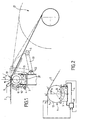
- Figure 1 is a schematic view, in cross section, of a flatness measuring device according to the invention, with winding below of the scroll plan.
- Figure 2 is a diagram of the cooling system of a roller.
- Figure 3 shows, in side view, another embodiment of the invention, with winding above the travel plane.
- FIG. 4 is a top view of the roller of FIG. 3.
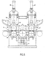
- Figure 5 is a schematic view, in cross section, of another embodiment of the invention.
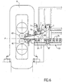
- FIG. 6 shows another embodiment of the invention, in another application.
- Figure 1 there is shown schematically, the mounting of a flatness measuring roller 1 to which a tape is applied metallic 2 which runs in a longitudinal direction parallel to the plane of the figure and is wound on a winder 21 which, in this example, is placed below the plan P of travel of the strip.
- the winding of the tape is carried out under traction, the winder 21 being provided, for this purpose, with known means which need not be described.
- the strip 2 is deflected by the roller 1 and applied to a sector angular of it, under a longitudinal tension determined by the winding control means.
- the flatness measuring roller 1 can be of any known type, for example example, the one described in French patent N ° 2,468,878 of the same society.
- a flatness roller comprises a tubular body 11 in which are housed housings 12 which are closed by a thin envelope 13 threaded onto the tubular body 11.
- a detection device by example a displacement probe 14 which comprises a fixed element taking support on the bottom of the housing 12 and a movable element bearing on the inner face of the casing 13 closing the housing 12 outwards.
- the roller 11 is rotatably mounted around its axis 10 and it is equipped a number of detectors 12, 14 distributed over its entire length so as to cover the width of the strip M applied to the roll 1.
- the measuring roller 1 can be placed downstream, in the direction of scrolling, of a hot rolling installation not shown in the Fig.
- the temperature of the hot strip arriving on the roller 1 can be, for example, between 250 ° C and 400 ° C in the case of a metal not ferrous but it could be higher. This results in overheating important of the roller by its external face.
- the outer face of the roller 1 is covered by the strip 2 only on an angular sector a, a 'relatively reduced whose angle at the center A does not normally exceed 20 ° and therefore includes a free sector a ', between 340 and 350 °.
- the invention takes advantage of this arrangement by performing forced cooling of the face external 13 of the roller by circulation of a heat transfer fluid along at least part of this free sector a, a 'and by determining the conditions of cooling so as to bring each detection zone to the same equilibrium temperature during its passage in the free sector.
- the roller 1 is placed below the strip and it is possible to immerse the lower part of the free sector in a tank 3 filled with a heat transfer liquid 31 such as water.
- This tray 3 is wide open at the top so that the lower part of the roller is submerged over a relatively large angular sector B, by example, of the order of 90 to 110 °.
- each part 15 of the envelope 13 closing a housing 12 constitutes a detection zone which heats up first in contact with strip 2 passing through the angular sector A but is immediately cooled in contact with water 31 passing through the sector b, b 'of angle at the center B.
- the tank 3 is connected to a circuit 4 for circulating the cooling fluid 31 between an inlet and an outlet, comprising means 41 for adjusting the cooling parameters such as the initial temperature and the circulation rate of the fluid 31 as a function of the temperature t 1 of the strip, so as to bring the outer face 13 of the roller to a determined temperature t 3 .
- each detection zone is therefore brought back at a constant temperature level before returning to the area angular A in contact with the strip 2. This ensures the repeatability of the measurement of the pressure applied by the strip to the wall 15 or of the displacement thereof since the thermal influence of the strip is exerted always the same way.
- the tape running speed may vary, for example depending on the thickness reduction carried out in the rolling mill.
- the strip 2 remains applied to the same part of the roller and this results in a temperature rise which could damage the sensors.
- the measuring roller 1 which serves as a deflector roller is then placed, also, above band 2 and it must be associated with a device for cooling placed on the side.
- This cooling device is then consisting of a box 30 having two longitudinal walls 33, 34 parallel to the axis 10 of the roller and extending to an edge 33 ', 34', placed close the outer face 13 of the roller.
- the ends 33 ', 34' are angularly separated so as to limit a cooling sector angle at center B at least equal to a quadrant.
- the box 30 Inside the box 30 is placed at least one spray bar fluid consisting of a pipe 35 connected to a circuit 36 for supplying a heat transfer fluid and provided with a plurality of orifices forming nozzles spray 37 of the fluid directed towards the external face 13 of the roller so the fluid jets are substantially contiguous and cover a sector angle of the roller, over the entire length thereof.
- the box 30 is provided with two spray bars 35 whose nozzles 37 are angularly and longitudinally offset so as to better distribute the fluid over the entire angular sector B.
- the circuit supply 36 is associated with a means 36 'for adjusting the flow sprayed in function of the temperature of the strip 2 to maintain the external face 13 of the roller 1 at a determined temperature, in front of application sector A.
- this is associated with a deflector roller 5 mounted at the end of a pair of arms 51 which can pivot around an axis 52 between a raised position for which the strip 2 is applied to the winder 21 and a position lowered for which the strip 2 is deflected by the roller 5 and is slightly away from the outside of the roller 1.
- the strip laminate is at a much higher temperature which can range, for example example from 700 to 1000 ° C, and must undergo a first cooling before to be wound into a reel.
- a cooling bench must then be interposed between the rolling mill and the winder which is therefore placed at a fairly large distance from the rolling mill.
- this first cooling is not homogeneous across the width of the strip and may cause uneven fiber shortening, variations in elongation due to rolling mill found only after complete cooling of the strip wound in a reel. If the measuring roller is placed just before the winding, at the outlet of the cooling bench, the measurement of the elongation distribution therefore risks being distorted.
- the measuring roller flatness 1 can be placed between two pairs of pinch rollers 8, 8 ' each comprising a fixed roller 81 and a movable roller 82 mounted on a support 83 sliding vertically between two guides of a frame 84, under the action of a jack 85.
- the flatness roller 1 is itself carried by a support cradle 16 mounted to slide vertically under the action of a jack 17.
- the strip In the lowered position of the rollers 82, 82 ', the strip is pinched between the two pairs of rollers 8, 8 'and the jack 17 for lifting the cradle support 16 allows the relative level of the measuring roller 1 to be adjusted by relative to the running plane of the strip and thus determine an angle A applying tape 2 to roller 1.
- At least one of the pinch rollers of each pair 8, 8 ' is rotated at a speed which can be adjusted separately on each pair 8, 8 '.
- Spray bars 35 arranged on either side of the roller 1 allow forced cooling of the free sector thereof.
- the flatness measurement of a hot strip could be useful in the case of a so-called "mini-mill” installation comprising a casting continuous in thin strip followed by some in-line finishing cages, a cooling bench and a winder.
- FIG. 6 which shows, by way of example, an arrangement of this type, only the last finishing cage 6 has been shown.
- the moving strip from left to right in the figure along a horizontal rolling plane P passes first between the two working rolls 60 of the cage 6 then on a cooling bench 23 comprising a support table consisting of a series of rollers 24 tangent to the travel plane P, as well as means which are not shown in the figure.
- the roller 1 for measuring flatness is mounted at the exit of the rolling mill but the strip can be put under tension by the winder placed at the end of the line. We admit, in fact, not to check the flatness on the tape head whose length is negligible when the strip is continuously cast.
- this is mounted on a support cradle 7 which can pivot, about an axis 70, on two aligned bearings fixed, for example, on the rolling stand 6.
- a jack 71 controls the pivoting of the roller 1 between a raised position shown in solid lines in FIG. 5 and a position lowered for which the roller 1 'is interposed between two rollers 25, 25 'of the roller table 23 and therefore determines the application on the measuring roller 1, of the strip 2 which, in this case, is energized by the winder placed at the end of the cooling bench 23 and not shown in the figure.
- the tensile force applied to the web by the winder can be adjusted according to the rolling speed between the working rolls 60, so as to make a winding with contiguous turns.
- the opening of the angular sector of application of the strip depends on the level of the lowered position 1 ′ of the roller 1 relative to the plane of the rollers 25, 25 ', which can be adjusted by means of the jack 71.
- the measuring roller 1 is associated to a cooling box 34 fixed on the cradle 7 and provided with a ramp 35 spraying a coolant on part of the free sector of the roller.
Landscapes
- Physics & Mathematics (AREA)
- General Physics & Mathematics (AREA)
- Engineering & Computer Science (AREA)
- Mechanical Engineering (AREA)
- Force Measurement Appropriate To Specific Purposes (AREA)
- Length Measuring Devices With Unspecified Measuring Means (AREA)
- Finish Polishing, Edge Sharpening, And Grinding By Specific Grinding Devices (AREA)
- Length Measuring Devices By Optical Means (AREA)
- Burglar Alarm Systems (AREA)
- Electrical Discharge Machining, Electrochemical Machining, And Combined Machining (AREA)
Abstract
Description
L'invention a pour objet un procédé et un dispositif de détection de planéité d'un produit en bande métallique défilant suivant une direction longitudinale et s'applique spécialement à des bandes se trouvant à une température élevée.The subject of the invention is a method and a device for detecting flatness of a metal strip product moving in one direction longitudinal and applies especially to bands located at a high temperature.
Lors du laminage de bandes de métal et notamment de tôles minces laminées, il peut se produire des défauts de planéité qui apparaissent lorsque la bande est au repos mais sont à l'état latent dans la bande sous traction. De tels défauts proviennent, en général, de légères variations, sur la largeur de la bande, de l'allongement réalisé par le laminage et peuvent être corrigés en agissant sur les conditions de laminage et, en particulier, sur la répartition, dans le sens transversal, de la pression de serrage appliquée entre les cylindres de travail.When rolling metal strips and especially thin sheets rolled, there may be flatness defects which appear when the strip is at rest but are latent in the strip under tension. Of such faults arise, in general, from slight variations, over the width of the strip, the elongation achieved by rolling and can be corrected by acting on the rolling conditions and, in particular, on the distribution, in the transverse direction, of the clamping pressure applied between the working cylinders.
A cet effet, il est possible, dans les laminoirs modernes, d'agir sur le profil de l'entrefer de passage du produit, par exemple en exerçant des efforts de cambrage sur les extrémités des cylindres de travail. On peut aussi utiliser un cylindre de soutien comprenant une enveloppe déformable montée rotative autour d'un arbre fixe et prenant appui sur celui-ci par une pluralité de vérins répartis sur la largeur de la bande et qui peuvent être réglés en position et en pression.To this end, it is possible, in modern rolling mills, to act on the profile of the product passage air gap, for example by exerting forces bending on the ends of the working cylinders. We can also use a support cylinder comprising a deformable envelope rotatably mounted around a fixed shaft and supported on it by a plurality of jacks spread across the width of the band and which can be adjusted in position and pressure.
Ces moyens de réglage sont commandés à partir des informations données par un dispositif de mesure, placé en aval du laminoir, et sensible aux variations, sur la largeur de la bande, de l'effort de traction appliqué sur celle-ci qui correspondent elles-mêmes aux variations d'allongement des fibres longitudinales de la bande.These adjustment means are controlled from the information data by a measuring device, placed downstream of the rolling mill, and sensitive to variations, over the width of the strip, of the tensile force applied to these which themselves correspond to the variations in elongation of the longitudinal fibers of the strip.
Un tel dispositif de mesure est constitué, habituellement, d'un rouleau déflecteur comprenant un corps cylindrique monté rotatif autour d'un axe perpendiculaire à la direction longitudinale de défilement de la bande. Celle-ci est appliquée sous traction sur un secteur angulaire de la face externe du rouleau qui est équipé d'une série de capteurs permettant de mesurer les variations de la pression locale d'application de la bande. Habituellement, ces détecteurs sont régulièrement écartés les uns des autres et répartis sur toute la longueur du rouleau, la bande étant ainsi divisée en une série de zones longitudinales ayant chacune une largeur déterminée, sur lesquelles on intègre la mesure du défaut latent à corriger.Such a measuring device usually consists of a roller deflector comprising a cylindrical body mounted to rotate about an axis perpendicular to the longitudinal direction of travel of the strip. This one is applied under tension to an angular sector of the external face of the roller which is equipped with a series of sensors to measure the variations in the local application pressure of the strip. Usually these detectors are regularly separated from each other and spread over the whole the length of the roll, the strip being thus divided into a series of zones longitudinal each having a determined width, on which we integrates the measurement of the latent fault to be corrected.
Dans une disposition connue décrite, par exemple, dans le document US-3.481.194, le rouleau déflecteur comprend un corps central tubulaire d'épaisseur suffisante pour donner la résistance nécessaire et muni, sur sa face externe, d'une pluralité de logements dans lesquels sont placés des capteurs de mesure.In a known arrangement described, for example, in the document US-3,481,194, the deflector roller comprises a tubular central body of sufficient thickness to give the necessary resistance and provided, on its external face, of a plurality of housings in which are placed measurement sensors.
D'une façon générale, un rouleau de mesure comprend une pluralité de zones de détection réparties sur toute sa longueur et munie chacune d'un capteur pour l'émission d'un signal dépendant de la pression d'application de la partie correspondante de la bande, lors du passage de cette zone de détection dans le secteur angulaire de contact de la bande avec le rouleau.Generally, a measuring roller comprises a plurality of detection zones distributed over its entire length and each provided with a sensor for the emission of a signal depending on the application pressure of the corresponding part of the strip, when passing this zone of detection in the angular sector of contact of the strip with the roller.
D'autre part, pour éviter des interférences entre les mesures effectuées sur deux zones de mesure adjacentes, les capteurs sont avantageusement décalés angulairement d'une zone à la suivante.On the other hand, to avoid interference between the measurements made on two adjacent measurement zones, the sensors are advantageously angularly offset from one zone to the next.
Dans une telle disposition, chaque capteur de mesure est sensible à la pression d'application de la bande mais peut également être influencé par d'autres facteurs qui peuvent perturber la mesure.In such an arrangement, each measurement sensor is sensitive to the tape application pressure but can also be influenced by other factors which may disturb the measurement.
Par exemple, pour éviter un contact direct entre les capteurs et la bande en défilement, chaque logement d'un capteur est fermé, vers l'extérieur, par une paroi de protection qui peut être constituée d'une enveloppe mince recouvrant l'ensemble du corps tubulaire du rouleau ou bien d'une pièce en forme de calotte qui se déforme légèrement pour transmettre aux capteurs la pression appliquée par la bande. Un tel dispositif est donc sensible aux déformations thermiques produites par une élévation de température du rouleau.For example, to avoid direct contact between the sensors and the strip running, each sensor housing is closed, towards the outside, by a protective wall which may consist of a thin envelope covering the entire tubular body of the roller or else a cap-shaped piece that deforms slightly to transmit to the sensors the pressure applied by the strip. Such a device is therefore sensitive to thermal deformations produced by an elevation of roller temperature.
De même, les capteurs de mesure ne sont pas prévus, normalement pour fonctionner à une température élevée.Likewise, measurement sensors are not provided, normally to operate at a high temperature.
C'est pourquoi, jusqu'à présent, les rouleaux de mesure de planéité étaient utilisés dans les installations de laminage à froid dans lesquels la bande laminée peut être maintenue à une température modérée.This is why, until now, the flatness measuring rollers were used in cold rolling plants in which the laminated tape can be kept at a moderate temperature.
Cependant, les défauts latents qui résultent des variations d'allongement sur la largeur de la bande apparaissent aussi lors du laminage à chaud et il est apparu qu'il serait intéressant d'éviter, dès ce moment, les risques de défauts de planéité. However, latent defects that result from variations of elongation over the width of the strip also appear during rolling hot and it appeared that it would be interesting to avoid, from this moment, the risks of flatness defects.
Pour cela, il avait semblé suffisant jusqu'à présent, d'associer au laminoir, un modèle mathématique permettant de prévoir les zones de défauts afin d'éviter, autant que possible leur apparition, en agissant sur les différents moyens de réglage du laminoir. Les défauts à corriger peuvent aussi être déterminés par des moyens optiques sur le produit hors traction, c'est-à-dire sur la tête de bande, avant l'enroulement sur la bobineuse. Un tel système ne permet donc pas de contrôler la planéité du produit sur toute sa longueur et il est donc préférable de détecter les défauts latents dès la sortie du laminoir.For that, it had seemed sufficient until now, to associate with the rolling mill, a mathematical model for predicting defect areas in order to avoid, as much as possible their appearance, by acting on the different means for adjusting the rolling mill. Faults to be corrected can also be determined by optical means on the product without traction, i.e. on the tape head, before winding on the winder. Such a system does therefore does not control the flatness of the product over its entire length and it it is therefore preferable to detect latent defects as soon as they exit the rolling mill.
A cet effet, on a proposé, dans le document EP-A-0.858.845, de placer dans une ligne de laminage à chaud, un rouleau de mesure sur lequel la bande peut être appliquée sous traction.To this end, it has been proposed in document EP-A-0.858.845 to place in a hot rolling line, a measuring roller on which the tape can be applied under traction.
Cependant, même dans le cas d'un métal non-ferreux tel que l'aluminium, la bande à chaud se trouve à une température élevée et il en résulte des perturbations dans les mesures qui doivent être compensées. On peut, par exemple, effectuer un étalonnage du rouleau à diverses températures pour apporter aux mesures les corrections nécessaires en fonction de la température de la bande mais un tel étalonnage n'est pas facile à réaliser.However, even in the case of a non-ferrous metal such as aluminum, the hot strip is at a high temperature and results from disturbances in the measurements which must be compensated. We can, for example, perform a roll calibration at various temperatures to make the necessary corrections to the measurements web temperature but such calibration is not easy to achieve.
L'invention a pour objet de résoudre ces problèmes grâce à des dispositions particulièrement simples qui peuvent s'appliquer à tous types de rouleaux de mesure de planéité et qui permettent d'éviter un étalonnage des capteurs en fonction des différentes températures de fonctionnement.The object of the invention is to solve these problems by means of particularly simple provisions which can apply to all types of flatness measuring rollers which avoid calibration of the sensors according to the different operating temperatures.
L'invention s'applique donc, d'une façon générale, à un procédé et un dispositif de détection de la planéité d'un produit en bande dans lequel la bande est mise sous tension et appliquée sur un secteur angulaire d'un rouleau de mesure monté rotatif autour d'un axe perpendiculaire à la direction longitudinale de défilement de la bande et ayant une face externe cylindrique comprenant un secteur angulaire de contact avec la bande et un secteur libre.The invention therefore generally applies to a method and a device for detecting the flatness of a strip product in which the strip is tensioned and applied to an angular sector of a measuring roller mounted to rotate about an axis perpendicular to the direction longitudinal travel of the strip and having a cylindrical external face comprising an angular sector of contact with the strip and a free sector.
Conformément à l'invention, on réalise un refroidissement forcé du rouleau par circulation d'un fluide caloporteur le long d'au moins une partie du secteur libre de la face externe du rouleau et l'on détermine les paramètres déterminant l'efficacité du refroidissement tels que l'ouverture du secteur angulaire de refroidissement le long duquel circule le fluide, la température initiale de celui-ci et le débit de circulation, de telle sorte que, après s'être échauffée en passant dans le secteur de contact avec la bande, la face externe du rouleau soit ramenée, par son passage dans le secteur de refroidissement du rouleau, à une température d'équilibre déterminée.According to the invention, a forced cooling of the roller by circulation of a heat transfer fluid along at least part of the free sector of the external face of the roller and the parameters are determined determining cooling efficiency such as opening up the sector cooling angle along which the fluid circulates, the temperature initial of it and the traffic flow, so that after getting heated when passing through the contact area with the strip, the face external of the roller is brought back, by its passage in the sector of cooling of the roller to a determined equilibrium temperature.
Dans un premier mode de réalisation particulièrement avantageux, on réalise le refroidissement forcé du rouleau par aspersion d'un fluide caloporteur au moyen de rampes d'aspersion réparties sur au moins une partie du secteur libre du rouleau et l'on règle au moins la température du fluide et le débit d'aspersion en fonction de la température de la bande, de la vitesse de défilement et des conditions d'échange thermique, de façon à ramener à un niveau déterminé la température de la face externe du rouleau immédiatement avant son passage dans le secteur de contact.In a first particularly advantageous embodiment, performs forced cooling of the roller by spraying a fluid coolant by means of spray bars distributed over at least one part of the free sector of the roller and at least the temperature of the fluid and the spraying rate as a function of the temperature of the strip, the running speed and heat exchange conditions, so that reduce the temperature of the external face of the roller to a determined level immediately before passing through the contact area.
Dans un autre mode de réalisation, le rouleau de mesure de planéité étant placé au-dessous de la bande, la face externe de celui-ci comprend une partie inférieure qui plonge dans un bain de liquide caloporteur ménagé dans une cuvette placée au-dessous du rouleau et associée à des moyens de mise en circulation du liquide avec un débit réglable entre un orifice d'entrée et un orifice de sortie de la cuvette, et l'on règle au moins la température initiale du liquide à son arrivée dans le bain et le débit de circulation, de façon à ramener à un niveau déterminé la température de la face externe du rouleau immédiatement avant son passage dans le secteur de contact.In another embodiment, the flatness measuring roller being placed below the strip, the external face of the latter comprises a lower part which plunges into a bath of heat transfer liquid formed in a bowl placed below the roller and associated with placing means circulating liquid with adjustable flow between an inlet and a outlet of the bowl, and at least the initial temperature of the liquid on arrival in the bath and the circulation rate, so as to bring at a certain level the temperature of the external face of the roller immediately before passing through the contact area.
Grâce à ces dispositions, la face externe du rouleau est ramenée,
avant son passage dans la zone de contact, à une température d'équilibre t
qui est liée à la température de la bande t1 et à la température initiale t2 du
fluide caloporteur par une formule de la forme :
L'invention couvre également un dispositif de détection de planéité pour la mise en oeuvre du procédé, comprenant un moyen de refroidissement forcé de la face externe du rouleau de mesure par circulation d'un fluide caloporteur le long d'au moins une partie du secteur libre du rouleau et des moyens de réglage des conditions de refroidissement pour le maintien de la face externe du rouleau à une température d'équilibre déterminée, avec refroidissement contrôlé de chaque zone de détection pendant son passage dans le secteur libre du rouleau.The invention also covers a flatness detection device for the implementation of the method, comprising a forced cooling means of the external face of the measuring roller by circulation of a heat transfer fluid along at least part of the free sector of the roller and the means of adjustment of the cooling conditions to maintain the external face of the roller at a determined equilibrium temperature, with cooling controlled each detection zone during its passage in the sector free from the roller.
L'invention s'applique spécialement aux rouleaux de mesure de planéité du type comprenant une pluralité de zones de détection réparties sur la longueur du rouleau et munies chacune d'un capteur pour l'émission d'un signal dépendant de la pression d'application d'une partie correspondante de la bande, lors du passage de ladite zone de détection dans le secteur angulaire de contact de la bande avec le rouleau, lesdites zones de détection étant ramenées à une même température d'équilibre à chaque passage dans le secteur libre du rouleau.The invention applies especially to rolls for measuring flatness of the type comprising a plurality of detection zones distributed over the length of the roll and each equipped with a sensor for the emission of a signal depending on the application pressure of a corresponding part of the strip, during the passage of said detection zone in the sector angular contact of the strip with the roller, said detection zones being brought to the same equilibrium temperature at each passage in the free sector of the roller.
L'invention couvre également d'autres caractéristiques avantageuses et sera mieux comprise par la description suivante de certains modes de réalisation, donnés à titre d'exemple, et représentés sur les dessins annexés.The invention also covers other advantageous features and will be better understood by the following description of certain modes of embodiment, given by way of example, and shown in the accompanying drawings.
La figure 1 est une vue schématique, en coupe transversale, d'un dispositif de mesure de planéité selon l'invention, avec enroulement au-dessous du plan de défilement.Figure 1 is a schematic view, in cross section, of a flatness measuring device according to the invention, with winding below of the scroll plan.
La figure 2 est un schéma du système de refroidissement d'un rouleau.Figure 2 is a diagram of the cooling system of a roller.
La figure 3 montre, en vue de côté, un autre mode de réalisation de l'invention, avec enroulement au-dessus du plan de défilement.Figure 3 shows, in side view, another embodiment of the invention, with winding above the travel plane.
La figure 4 est une vue de dessus du rouleau de la figure 3.FIG. 4 is a top view of the roller of FIG. 3.
La figure 5 est une vue schématique, en coupe transversale, d'un autre mode de réalisation de l'invention.Figure 5 is a schematic view, in cross section, of another embodiment of the invention.
La figure 6 montre un autre mode de réalisation de l'invention, dans une autre application.FIG. 6 shows another embodiment of the invention, in another application.
Sur la figure 1, on a représenté schématiquement, le montage d'un
rouleau de mesure de planéité 1 sur lequel est appliquée une bande
métallique 2 qui défile suivant une direction longitudinale parallèle au plan de
la figure et s'enroule sur une bobineuse 21 qui, dans cet exemple, est placée
au-dessous du plan P de défilement de la bande. L'enroulement de la bande
est effectué sous traction, la bobineuse 21 étant munie, à cet effet, de
moyens connus qui n'ont pas besoin d'être décrits. In Figure 1, there is shown schematically, the mounting of a
La bande 2 est déviée par le rouleau 1 et appliquée sur un secteur
angulaire de celui-ci, sous une tension longitudinale déterminée par les
moyens de commande de l'enroulement.The strip 2 is deflected by the
Le rouleau de mesure de planéité 1 peut être de tout type connu, par
exemple, celui qui est décrit dans le brevet français N°2.468.878 de la même
société. On sait que, d'une façon générale, un tel rouleau de planéité
comprend un corps tubulaire 11 dans lequel sont ménagés des logements 12
qui sont fermés par une enveloppe mince 13 enfilée sur le corps tubulaire 11.
A l'intérieur de chaque logement 12 est placé un dispositif de détection, par
exemple un palpeur de déplacement 14 qui comprend un élément fixe prenant
appui sur le fond du logement 12 et un élément mobile prenant appui sur la
face interne de l'enveloppe 13 fermant le logement 12 vers l'extérieur.The
Le rouleau 11 est monté rotatif autour de son axe 10 et il est équipé
d'un certain nombre de détecteurs 12, 14 répartis sur toute sa longueur de
façon à couvrir la largeur de la bande M appliquée sur le rouleau 1.The
Une telle disposition est bien connue et ne nécessite pas une description détaillée. D'autres dispositions peuvent être utilisées pour mesurer les efforts appliqués sur le rouleau en plusieurs zones de détection réparties sur la longueur de celui-ci.Such an arrangement is well known and does not require a detailed description. Other arrangements can be used to measure the forces applied to the roller in several detection zones distributed along the length of it.
Jusqu'à présent, de tels rouleaux de planéité n'étaient utilisés que dans
des installations de laminage à froid dans lesquelles la bande laminée
présente une température modérée. Les dispositions selon l'invention
permettent, en revanche, de mesurer la planéité d'une bande à température
élevée, le rouleau de mesure 1 pouvant être placé en aval, dans le sens de
défilement, d'une installation de laminage à chaud non représentée sur la
figure.Until now, such flatness rollers have only been used in
cold rolling plants in which the rolled strip
has a moderate temperature. The arrangements according to the invention
allow, on the other hand, to measure the flatness of a strip at temperature
high, the
La température de la bande à chaud arrivant sur le rouleau 1 peut être,
par exemple, comprise entre 250°C et 400°C dans le cas d'un métal non
ferreux mais elle pourrait être plus élevée. Il en résulte un échauffement
important du rouleau par sa face externe.The temperature of the hot strip arriving on the
Cependant, comme le montre la figure 2, la face externe du rouleau 1
n'est recouverte par la bande 2 que sur un secteur angulaire a, a' relativement
réduit dont l'angle au centre A ne dépasse pas, normalement, 20° et
comprend donc un secteur libre a', a compris entre 340 et 350°. L'invention
met à profit cette disposition en réalisant un refroidissement forcé de la face
externe 13 du rouleau par circulation d'un fluide caloporteur le long d'au moins
une partie de ce secteur libre a, a' et en déterminant les conditions de
refroidissement de façon à amener chaque zone de détection à une même
température d'équilibre pendant son passage dans le secteur libre.However, as shown in Figure 2, the outer face of the
Dans la disposition de la figure 1, par exemple, le rouleau 1 est placé
au-dessous de la bande et il est possible d'immerger la partie inférieure du
secteur libre dans un bac 3 rempli d'un liquide caloporteur 31 tel que de l'eau.
Ce bac 3 est largement ouvert vers le haut de façon que la partie inférieure du
rouleau soit immergée sur un secteur angulaire B relativement important, par
exemple, de l'ordre de 90 à 110°.In the arrangement of Figure 1, for example, the
Ainsi, à chaque tour du rouleau, chaque partie 15 de l'enveloppe 13
fermant un logement 12, constitue une zone de détection qui s'échauffe
d'abord au contact de la bande 2 en passant dans le secteur angulaire A mais
est immédiatement refroidie au contact de l'eau 31 en passant dans le secteur
b, b' d'angle au centre B.Thus, at each turn of the roller, each part 15 of the
Si l'on appelle t1 la température de la bande 2 et t2 la température du
liquide 31 contenu dans le bac 3, la température t de la face externe du
rouleau, après son passage dans le liquide 31 peut être donnée par la
formule :
Ces coefficients d'échange thermique dépendent notamment de la
nature de l'enveloppe mince 13 constituant la face externe du rouleau 1, du
fluide de refroidissement 31 et de l'angle d'ouverture des secteurs A et B.These heat exchange coefficients depend in particular on the
nature of the
Le bac 3 est relié à un circuit 4 de mise en circulation du fluide de
refroidissement 31 entre une entrée et une sortie, comprenant des moyens 41
de réglage des paramètres de refroidissement tels que la température initiale
et le débit de circulation du fluide 31 en fonction de la température t1 de la
bande, de façon à ramener la face externe 13 du rouleau à une température
déterminée t3. The
A chaque tour du rouleau, chaque zone de détection est donc ramenée à un niveau de température constant avant de repasser dans le secteur angulaire A au contact de la bande 2. On assure ainsi la répétitivité de la mesure de la pression appliquée par la bande sur la paroi 15 ou du déplacement de celle-ci puisque l'influence thermique de la bande s'exerce toujours de la même façon.Each turn of the roller, each detection zone is therefore brought back at a constant temperature level before returning to the area angular A in contact with the strip 2. This ensures the repeatability of the measurement of the pressure applied by the strip to the wall 15 or of the displacement thereof since the thermal influence of the strip is exerted always the same way.
Comme le refroidissement est effectué à chaque tour, avec un rapport constant entre le temps d'échauffement et le temps de refroidissement, la vitesse de défilement de la bande peut varier, par exemple en fonction de la réduction d'épaisseur effectuée dans le laminoir.As the cooling is performed at each turn, with a ratio constant between the heating time and the cooling time, the tape running speed may vary, for example depending on the thickness reduction carried out in the rolling mill.
Cependant, on peut être amené à arrêter le défilement, par exemple pour intervenir sur le laminoir ou une autre partie de l'installation. Dans ce cas, la bande 2 reste appliquée sur la même partie du rouleau et il en résulte une élévation de température qui risque de détériorer les capteurs.However, it may be necessary to stop the scrolling, for example to work on the rolling mill or another part of the installation. In that case, the strip 2 remains applied to the same part of the roller and this results in a temperature rise which could damage the sensors.
C'est pourquoi, il est prévu, en cas d'arrêt, d'écarter la bande 2 du
rouleau 1 au moyen d'un rouleau déflecteur 5 monté rotatif aux extrémités de
deux bras de support 51 qui peuvent pivoter autour d'un axe 52 entre une
position écartée, représentée en trait plein sur la figure, pour laquelle la bande
2 est appliquée normalement sur la bande 1 et une position engagée,
représentée en trait mixte, pour laquelle la bande 1 est soulevée par le
rouleau 5 et légèrement écartée de la face externe 13 du rouleau 1.This is why it is planned, in the event of a stop, to separate the band 2 from the
Sur la figure 3, on a représenté, en vue de côté, un autre mode de
réalisation dans lequel la bobineuse 21 est placée au-dessus du plan P de
défilement de la bande 2.In Figure 3, there is shown, in side view, another mode of
embodiment in which the
Le rouleau de mesure 1 qui sert de rouleau déflecteur est alors placé,
également, au-dessus de la bande 2 et il doit être associé à un dispositif de
refroidissement placé sur le côté. Ce dispositif de refroidissement est alors
constitué d'un caisson 30 ayant deux parois longitudinales 33, 34 parallèles à
l'axe 10 du rouleau et s'étendant jusqu'à un bord 33', 34', placé à proximité
immédiate de la face externe 13 du rouleau. Les extrémités 33', 34' sont
écartées angulairement de façon à limiter un secteur de refroidissement
d'angle au centre B au moins égal à un quadrant.The measuring
A l'intérieur du caisson 30 est placée au moins une rampe d'aspersion
de fluide constituée d'une conduite 35 reliée à un circuit 36 d'alimentation en
un fluide caloporteur et munie d'une pluralité d'orifices formant des buses
d'aspersion 37 du fluide dirigées vers la face externe 13 du rouleau de façon
que les jets de fluide soient sensiblement jointifs et couvrent un secteur
angulaire du rouleau, sur toute la longueur de celui-ci. Avantageusement, le
caisson 30 est muni de deux rampes d'aspersion 35 dont les buses 37 sont
décalées angulairement et longitudinalement de façon à mieux répartir le
fluide sur l'ensemble du secteur angulaire B. Comme précédemment, le circuit
d'alimentation 36 est associé à un moyen 36' de réglage du débit aspergé en
fonction de la température de la bande 2 pour maintenir la face externe 13 du
rouleau 1 à une température déterminée, en avant du secteur d'application A.Inside the
Pour éviter un échauffement excessif d'une zone de détection en cas
d'arrêt du défilement et, par conséquent, de la rotation du rouleau de mesure
1, celui-ci est associé à un rouleau déflecteur 5 monté à l'extrémité d'une
paire de bras 51 pouvant pivoter autour d'un axe 52 entre une position relevée
pour laquelle la bande 2 est appliquée sur la bobineuse 21 et une position
abaissée pour laquelle la bande 2 est déviée par le rouleau 5 et se trouve
légèrement écartée de la face externe du rouleau 1.To avoid excessive heating of a detection zone in the event of
stop the scrolling and, consequently, the rotation of the measuring
Dans les deux modes de réalisation qui viennent d'être décrits, pour
permettre l'application sous tension de la bande 2 sur un secteur angulaire du
rouleau de mesure de planéité 1, celui-ci constitue un rouleau déflecteur placé
immédiatement en amont, dans le sens de défilement, de la bobineuse 21 de
façon à déterminer l'application sous tension de la bande sur un secteur
angulaire du rouleau de mesure 1.In the two embodiments which have just been described, for
allow the application of strip 2 under tension to an angular sector of the
Ceci ne présente pas d'inconvénient lorsque la bobineuse est placée à faible distance du laminoir comme, par exemple, dans le cas du laminage de métaux non ferreux tels que l'aluminium qui, à la sortie du laminage à chaud, se trouvent à une température relativement modérée, de l'ordre de 300 à 400°C et peuvent être enroulés en bobine immédiatement après la mesure.This is not a problem when the winder is placed at short distance from the rolling mill, for example in the case of rolling non-ferrous metals such as aluminum which, at the end of hot rolling, are at a relatively moderate temperature, around 300 to 400 ° C and can be wound on a reel immediately after the measurement.
En revanche, dans le cas des métaux ferreux tel que l'acier, la bande laminée se trouve à une température beaucoup plus élevée pouvant aller, par exemple de 700 à 1000°C, et doit subir un premier refroidissement avant d'être enroulée en bobine. Un banc de refroidissement doit alors être interposé entre le laminoir et la bobineuse qui se trouve donc placée à une distance assez importante du laminoir. Cependant, ce premier refroidissement n'est pas homogène sur la largeur de la bande et peut provoquer un raccourcissement inégal des fibres, les variations d'allongement dues au laminoir ne se retrouvant qu'après refroidissement complet de la bande enroulée en bobine. Si le rouleau de mesure est placé juste avant l'enroulement, à la sortie du banc de refroidissement, la mesure de la répartition d'allongement risque donc d'être faussée.On the other hand, in the case of ferrous metals such as steel, the strip laminate is at a much higher temperature which can range, for example example from 700 to 1000 ° C, and must undergo a first cooling before to be wound into a reel. A cooling bench must then be interposed between the rolling mill and the winder which is therefore placed at a fairly large distance from the rolling mill. However, this first cooling is not homogeneous across the width of the strip and may cause uneven fiber shortening, variations in elongation due to rolling mill found only after complete cooling of the strip wound in a reel. If the measuring roller is placed just before the winding, at the outlet of the cooling bench, the measurement of the elongation distribution therefore risks being distorted.
Lorsqu'un refroidissement est nécessaire avant l'enroulement en bobine, il est donc plus avantageux de placer le rouleau de mesure à la sortie du laminoir, avant le banc de refroidissement.When cooling is required before winding in coil, it is therefore more advantageous to place the measuring roller at the outlet of the rolling mill, before the cooling bench.
Cependant, s'il faut attendre l'enroulement sur la bobineuse de la tête de la bande pour mettre celle-ci sous tension, il ne sera pas possible de contrôler la planéité de la bande sur une longueur assez importante de celle-ci.However, if you have to wait for the winding on the head winder tape to turn it on, it will not be possible to check the flatness of the strip over a fairly long length thereof.
Pour éviter de tels inconvénients, il est donc préférable de mettre la bande sous tension au niveau du rouleau de mesure, dès la sortie du laminoir.To avoid such disadvantages, it is therefore preferable to put the strip under tension at the measuring roller, as soon as it leaves the rolling mill.
A cet effet, comme le montre la figure 5, le rouleau de mesure de
planéité 1 peut être placé entre deux paires de rouleaux pinceurs 8, 8'
comprenant chacune un rouleau fixe 81 et un rouleau mobile 82 monté sur un
support 83 coulissant verticalement entre deux guides d'un châssis 84, sous
l'action d'un vérin 85.To this end, as shown in Figure 5, the measuring
Le rouleau de planéité 1 est lui-même porté par un berceau de support
16 monté coulissant verticalement sous l'action d'un vérin 17.The
En position abaissée des rouleaux 82, 82', la bande est pincée entre
les deux paires de rouleaux 8, 8' et le vérin 17 de soulèvement du berceau de
support 16 permet de régler le niveau relatif du rouleau de mesure 1 par
rapport au plan de défilement de la bande et de déterminer ainsi un angle A
d'application de la bande 2 sur le rouleau 1.In the lowered position of the
Dans cette disposition, au moins l'un des rouleaux pinceurs de chaque
paire 8, 8' est entraíné en rotation à une vitesse qui peut être réglée
séparément sur chaque paire 8, 8'.In this arrangement, at least one of the pinch rollers of each
De la sorte, il est possible de soumettre la section de la bande
comprise entre les deux paires de rouleaux 8, 8' à une tension déterminée, en
réglant séparément les vitesses de rotation des rouleaux pinceurs 8, 8' placés,
respectivement, en amont et en aval du rouleau de mesure 1.In this way, it is possible to submit the section of the strip
between the two pairs of
Des rampes d'aspersion 35 disposées de part et d'autre du rouleau 1
permettent de réaliser un refroidissement forcé du secteur libre de celui-ci. Spray bars 35 arranged on either side of the
D'autres rampes d'aspersion 38 peuvent être associées aux deux
paires de rouleaux pinceurs 8, 8'.Other spray bars 38 can be associated with the two
pairs of
Il est ainsi possible, comme précédemment, de régler l'intensité du
refroidissement de façon à maintenir la face externe 13 du rouleau 1 à une
température déterminée, ce qui permet d'assurer la répétitivité des mesures.It is thus possible, as before, to adjust the intensity of the
cooling so as to maintain the
Il est à noter que le réglage individuel des vitesses de rotation des deux
paires de rouleaux pinceurs 8, 8' permet de régler séparément les tensions
appliquées sur la bande dans chaque section de celle-ci, respectivement
entre la sortie du laminoir et les rouleaux pinceurs 8, sur le rouleau de mesure
1 entre les deux paires de rouleaux pinceurs 8, 8' et entre les rouleaux
pinceurs 8' et la bobineuse 21.It should be noted that the individual adjustment of the rotational speeds of the two
pairs of
Mais l'invention ne se limite pas aux détails des modes de réalisation qui viennent d'être décrits à titre d'exemple et couvre également d'autres variantes ou d'autres applications restant dans le cadre de protection défini par les revendications.But the invention is not limited to the details of the embodiments which have just been described by way of example and also covers other variants or other applications remaining within the defined protection framework by the claims.
Par exemple, la mesure de planéité d'une bande à chaud pourrait être utile dans le cas d'une installation dite " mini-mill " comportant une coulée continue en bande mince suivie de quelques cages finisseuses en ligne, d'un banc de refroidissement et d'une bobineuse.For example, the flatness measurement of a hot strip could be useful in the case of a so-called "mini-mill" installation comprising a casting continuous in thin strip followed by some in-line finishing cages, a cooling bench and a winder.
Sur la figure 6 qui montre, à titre d'exemple, une disposition de ce type,
on a représenté seulement la dernière cage de finition 6. La bande qui défile
de la gauche vers la droite sur la figure suivant un plan horizontal de laminage
P passe d'abord entre les deux cylindres de travail 60 de la cage 6 puis sur un
banc de refroidissement 23 comportant une table de support constituée d'une
série de rouleaux 24 tangents au plan de défilement P, ainsi que des moyens
de refroidissement qui ne sont pas représentés sur la figure.In FIG. 6 which shows, by way of example, an arrangement of this type,
only the last finishing cage 6 has been shown. The moving strip
from left to right in the figure along a horizontal rolling plane
P passes first between the two working
Dans ce mode de réalisation de l'invention, le rouleau 1 de mesure de
planéité est monté à la sortie du laminoir mais la bande peut être mise sous
tension par la bobineuse placée à l'extrémité de la ligne. On admet, en effet,
de ne pas contrôler la planéité sur la tête de bande dont la longueur est
négligeable lorsque la bande est coulée en continu.In this embodiment of the invention, the
Cependant, pour déterminer l'angle d'application de la bande sur le
rouleau de mesure 1, celui-ci est monté sur un berceau de support 7 qui peut
pivoter, autour d'un axe 70, sur deux paliers alignés fixés, par exemple, sur la
cage de laminage 6. Un vérin 71 commande le pivotement du rouleau 1 entre
une position relevée représentée en trait plein sur la figure 5 et une position
abaissée pour laquelle le rouleau 1' s'interpose entre deux rouleaux
successifs 25, 25' de la table à rouleaux 23 et détermine donc l'application sur
le rouleau de mesure 1, de la bande 2 qui, dans ce cas, est mise sous tension
par la bobineuse placée à l'extrémité du banc de refroidissement 23 et non
représentée sur la figure.However, to determine the angle of application of the strip on the
measuring
L'effort de traction appliqué sur la bande par la bobineuse peut être réglé en fonction de la vitesse de laminage entre les cylindres de travail 60, de façon à réaliser un enroulement à spires jointives.The tensile force applied to the web by the winder can be adjusted according to the rolling speed between the working rolls 60, so as to make a winding with contiguous turns.
L'ouverture du secteur angulaire d'application de la bande dépend du
niveau de la position abaissée 1' du rouleau 1 par rapport au plan des
rouleaux 25, 25', qui peut être réglé au moyen du vérin 71.The opening of the angular sector of application of the strip depends on the
level of the lowered
Comme dans le cas de la figure 3, le rouleau de mesure 1 est associé
à un caisson de refroidissement 34 fixé sur le berceau 7 et muni de rampe 35
d'aspersion d'un fluide de refroidissement sur une partie du secteur libre du
rouleau.As in the case of Figure 3, the measuring
En cas d'arrêt du défilement, il suffit de commander un relèvement
immédiat du berceau 7 pour écarter le rouleau de mesure de la bande afin
d'éviter son échauffement.If the scrolling stops, just order a bearing
immediately from
Les signes de référence insérés après les caractéristiques techniques mentionnées dans les revendications, ont pour seul but de faciliter la compréhension de ces dernières et n'en limitent aucunement la portée.The reference signs inserted after the technical characteristics mentioned in the claims, have the sole purpose of facilitating the understanding of them and in no way limit their scope.
Claims (15)
caractérisé par le fait que l'on réalise un refroidissement forcé du rouleau (1) par circulation d'un fluide caloporteur le long d'au moins une partie du secteur libre de la face externe (13) du rouleau (1) et que l'on détermine les paramètres déterminant l'efficacité du refroidissement tels que l'ouverture (B) du secteur angulaire de refroidissement le long duquel circule le fluide, la température initiale de celui-ci et le débit de circulation, de telle sorte que, après s'être échauffée en passant dans le secteur (a, a') de contact avec la bande (2), la face externe (13) du rouleau (1) soit ramenée, par son passage dans le secteur (b, b') de refroidissement du rouleau (1), à une température d'équilibre déterminée.Method for detecting the flatness of a metal strip product moving in a longitudinal direction and being at a high temperature, in which the strip (2) is tensioned and applied to an angular sector of a measuring roller ( 1) rotatably mounted about an axis perpendicular to the longitudinal direction of travel of the strip (2) and having a cylindrical external face (13) comprising an angular sector of contact with the strip and a free sector,
characterized by the fact that a forced cooling of the roller (1) is carried out by circulation of a heat-transfer fluid along at least part of the free sector of the external face (13) of the roller (1) and that the the parameters determining the cooling efficiency are determined such as the opening (B) of the angular cooling sector along which the fluid circulates, the initial temperature thereof and the circulation rate, so that, after having heated up while passing through the sector (a, a ') in contact with the strip (2), the external face (13) of the roller (1) is brought back, by its passage in the sector (b, b') cooling the roller (1) to a determined equilibrium temperature.
caractérisé par le fait qu'il comprend des moyens (3, 34) de refroidissement forcé de la face externe (13) du rouleau (1) par circulation d'un fluide caloporteur le long d'au moins une partie (b, b') du secteur libre du rouleau (1) et des moyens (30) de réglage des conditions de refroidissement pour le maintien de la face externe (13) du rouleau (1) à une température déterminée.Device for detecting the flatness of a strip product (2) traveling in a longitudinal direction and subjected to a tensile force, comprising a measuring roller (1) rotatably mounted around an axis perpendicular to the longitudinal direction of travel and on which the strip (2) is applied under tension, said roller (1) having a cylindrical external face (13) comprising an angular sector (a, a ') of contact with the strip and a free sector ,.
characterized by the fact that it comprises means (3, 34) for forced cooling of the external face (13) of the roller (1) by circulation of a heat transfer fluid along at least one part (b, b ' ) the free sector of the roller (1) and means (30) for adjusting the cooling conditions for maintaining the external face (13) of the roller (1) at a determined temperature.
Applications Claiming Priority (2)
| Application Number | Priority Date | Filing Date | Title |
|---|---|---|---|
| FR0013495A FR2815705B1 (en) | 2000-10-20 | 2000-10-20 | PLANAR DETECTION METHOD AND DEVICE |
| FR0013495 | 2000-10-20 |
Publications (2)
| Publication Number | Publication Date |
|---|---|
| EP1199543A1 true EP1199543A1 (en) | 2002-04-24 |
| EP1199543B1 EP1199543B1 (en) | 2009-09-23 |
Family
ID=8855583
Family Applications (1)
| Application Number | Title | Priority Date | Filing Date |
|---|---|---|---|
| EP01402728A Expired - Lifetime EP1199543B1 (en) | 2000-10-20 | 2001-10-19 | Method and device for flatness detection |
Country Status (9)
| Country | Link |
|---|---|
| US (1) | US6729757B2 (en) |
| EP (1) | EP1199543B1 (en) |
| KR (1) | KR100844875B1 (en) |
| CN (1) | CN1189258C (en) |
| AT (1) | ATE443845T1 (en) |
| DE (1) | DE60139976D1 (en) |
| ES (1) | ES2331723T3 (en) |
| FR (1) | FR2815705B1 (en) |
| RU (1) | RU2263000C2 (en) |
Cited By (6)
| Publication number | Priority date | Publication date | Assignee | Title |
|---|---|---|---|---|
| WO2008037408A1 (en) * | 2006-09-25 | 2008-04-03 | Sms Demag Ag | Method and device for winding metal strips onto a coiling mandrel |
| EP1944570A1 (en) | 2007-01-15 | 2008-07-16 | SMS Meer GmbH | Method and device for recording the straightness of elongated products |
| WO2017080955A1 (en) * | 2015-11-10 | 2017-05-18 | Primetals Technologies France SAS | Method for measuring the flatness of a metal product and associated device |
| CN110285910A (en) * | 2019-06-27 | 2019-09-27 | 利辛县亿隆筛网有限公司 | A kind of macromolecule silk screen tension detecting apparatus |
| JP2022538520A (en) * | 2019-06-25 | 2022-09-05 | エス・エム・エス・グループ・ゲゼルシャフト・ミト・ベシュレンクテル・ハフツング | Flatness measuring device for measuring the flatness of metal strips |
| CN118066992A (en) * | 2024-04-17 | 2024-05-24 | 中铁北京工程局集团有限公司 | Railway box girder positioning net sheet detection device |
Families Citing this family (13)
| Publication number | Priority date | Publication date | Assignee | Title |
|---|---|---|---|---|
| DE10131850B4 (en) * | 2001-06-30 | 2013-04-25 | Sms Siemag Aktiengesellschaft | Thin strip reel with flatness measuring roll |
| DE10224938B4 (en) * | 2002-06-04 | 2010-06-17 | Bwg Bergwerk- Und Walzwerk-Maschinenbau Gmbh | Method and device for flatness measurement of bands |
| DE10321865B4 (en) * | 2003-05-14 | 2013-06-27 | Betriebsforschungsinstitut VDEh - Institut für angewandte Forschung GmbH | Measuring device for a longitudinally moving belt and measuring method for process parameters of a belt conveyor |
| AT501314B1 (en) * | 2004-10-13 | 2012-03-15 | Voest Alpine Ind Anlagen | METHOD AND DEVICE FOR CONTINUOUS PRODUCTION OF A THIN METAL STRIP |
| DE102006059244A1 (en) * | 2006-10-21 | 2008-04-24 | Sms Demag Ag | Device for measuring the strip tension in a metallic strip |
| DE102007005378A1 (en) * | 2007-02-02 | 2008-08-07 | Siemens Ag | Operating method for a reel device for winding or unwinding a tape and control device and reel device for this purpose |
| JP4991365B2 (en) * | 2007-03-29 | 2012-08-01 | カヤバ工業株式会社 | Dimension measuring apparatus and dimension measuring method |
| CN102189117B (en) * | 2010-03-16 | 2013-05-29 | 宝山钢铁股份有限公司 | Cold rolled steel strip straightness feedforward control method based on transverse performance detection |
| CN103406363B (en) * | 2013-08-13 | 2015-02-25 | 山西太钢不锈钢股份有限公司 | Method for displaying selection states of hot continuous rolling detection instruments |
| DE102014115023A1 (en) * | 2014-10-16 | 2016-04-21 | Bwg Bergwerk- Und Walzwerk-Maschinenbau Gmbh | Flatness measuring roll with measuring bar in strip running direction |
| EP3138639B1 (en) * | 2015-09-03 | 2021-03-24 | SMS group GmbH | Method for manufacturing a metallic belt by means of endless rolling |
| EP4032629A1 (en) * | 2021-01-25 | 2022-07-27 | Primetals Technologies Germany GmbH | Flatness measurement in aluminium rolling mills |
| CN115356008B (en) * | 2022-09-20 | 2023-04-04 | 深圳市东河仪表有限公司 | Temperature sensor |
Citations (3)
| Publication number | Priority date | Publication date | Assignee | Title |
|---|---|---|---|---|
| EP0775890A1 (en) * | 1995-11-27 | 1997-05-28 | Kawasaki Steel Corporation | Strip shape detecting apparatus |
| EP0858845A1 (en) * | 1997-02-06 | 1998-08-19 | Sms Schloemann-Siemag Aktiengesellschaft | Roller for measuring flatness |
| WO2001005530A1 (en) * | 1999-07-15 | 2001-01-25 | Pohang Iron & Steel Co., Ltd. | Apparatus for measuring the strip flatness |
Family Cites Families (10)
| Publication number | Priority date | Publication date | Assignee | Title |
|---|---|---|---|---|
| DE1573407B1 (en) * | 1965-10-05 | 1970-09-03 | Asea Ab | Arrangement in strip rolling mills to measure the distribution of the strip tension over the strip width |
| US3826132A (en) * | 1973-06-01 | 1974-07-30 | Bethlehem Steel Corp | Device for producing a visual display of the transverse tension profile of a moving steel strip |
| US4082101A (en) * | 1975-08-07 | 1978-04-04 | Hazelett Strip-Casting Corporation | Coolant nozzle apparatus in twin-belt continuous casting machines |
| DE2633351C2 (en) * | 1976-07-24 | 1983-11-17 | Hoesch Werke Ag, 4600 Dortmund | Device for measuring the flatness of metal strips |
| FR2422451A1 (en) * | 1978-04-13 | 1979-11-09 | Usinor | METHOD AND DEVICE FOR CONTROL OF THE FLATNESS OF A COLD ROLLED METAL STRIP |
| IT1182868B (en) * | 1985-09-20 | 1987-10-05 | Randolph Norwood Mitchell | PROCEDURE AND EQUIPMENT FOR THE CONTINUOUS CONTROL AND / OR CORRECTION OF THE PROFILE AND FLATNESS OF METAL AND SIMILAR TAPES |
| SE461298B (en) * | 1988-06-02 | 1990-01-29 | Asea Brown Boveri | PLANET METERS FOR ROLLED BANDS |
| DE59811286D1 (en) * | 1997-02-26 | 2004-06-03 | Siemens Ag | DEVICE FOR MEASURING THE TENSION DISTRIBUTION IN A METAL STRIP |
| US6266983B1 (en) * | 1998-12-09 | 2001-07-31 | Kawasaki Steel Corporation | Method and apparatus for detecting flaws in strip, method of manufacturing cold-rolled steel sheet and pickling equipment for hot-rolled steel strip |
| DE19918699B4 (en) * | 1999-04-26 | 2008-03-27 | Betriebsforschungsinstitut VDEh - Institut für angewandte Forschung GmbH | Measuring roller for determining flatness deviations |
-
2000
- 2000-10-20 FR FR0013495A patent/FR2815705B1/en not_active Expired - Fee Related
-
2001
- 2001-10-19 RU RU2001128439/02A patent/RU2263000C2/en active
- 2001-10-19 AT AT01402728T patent/ATE443845T1/en active
- 2001-10-19 ES ES01402728T patent/ES2331723T3/en not_active Expired - Lifetime
- 2001-10-19 US US09/982,538 patent/US6729757B2/en not_active Expired - Lifetime
- 2001-10-19 DE DE60139976T patent/DE60139976D1/en not_active Expired - Lifetime
- 2001-10-19 EP EP01402728A patent/EP1199543B1/en not_active Expired - Lifetime
- 2001-10-19 CN CNB011433191A patent/CN1189258C/en not_active Expired - Lifetime
- 2001-10-20 KR KR1020010064933A patent/KR100844875B1/en active IP Right Grant
Patent Citations (3)
| Publication number | Priority date | Publication date | Assignee | Title |
|---|---|---|---|---|
| EP0775890A1 (en) * | 1995-11-27 | 1997-05-28 | Kawasaki Steel Corporation | Strip shape detecting apparatus |
| EP0858845A1 (en) * | 1997-02-06 | 1998-08-19 | Sms Schloemann-Siemag Aktiengesellschaft | Roller for measuring flatness |
| WO2001005530A1 (en) * | 1999-07-15 | 2001-01-25 | Pohang Iron & Steel Co., Ltd. | Apparatus for measuring the strip flatness |
Cited By (11)
| Publication number | Priority date | Publication date | Assignee | Title |
|---|---|---|---|---|
| WO2008037408A1 (en) * | 2006-09-25 | 2008-04-03 | Sms Demag Ag | Method and device for winding metal strips onto a coiling mandrel |
| CN101516540B (en) * | 2006-09-25 | 2013-05-29 | Sms西马格股份公司 | Method and device for winding metal strips onto a coiling mandrel |
| EP1944570A1 (en) | 2007-01-15 | 2008-07-16 | SMS Meer GmbH | Method and device for recording the straightness of elongated products |
| CN101226055B (en) * | 2007-01-15 | 2013-06-12 | Sms米尔股份有限公司 | Method and device for recording the straightness of elongated products |
| WO2017080955A1 (en) * | 2015-11-10 | 2017-05-18 | Primetals Technologies France SAS | Method for measuring the flatness of a metal product and associated device |
| US11235365B2 (en) | 2015-11-10 | 2022-02-01 | Clecim S.A.S. | Method for measuring the flatness of a metal product and associated device |
| JP2022538520A (en) * | 2019-06-25 | 2022-09-05 | エス・エム・エス・グループ・ゲゼルシャフト・ミト・ベシュレンクテル・ハフツング | Flatness measuring device for measuring the flatness of metal strips |
| EP3990200B1 (en) * | 2019-06-25 | 2024-02-14 | SMS Group GmbH | Flatness-measuring apparatus for measuring the flatness of a metal strip |
| CN110285910A (en) * | 2019-06-27 | 2019-09-27 | 利辛县亿隆筛网有限公司 | A kind of macromolecule silk screen tension detecting apparatus |
| CN110285910B (en) * | 2019-06-27 | 2021-03-12 | 利辛县亿隆筛网有限公司 | Polymer silk screen tension detection device |
| CN118066992A (en) * | 2024-04-17 | 2024-05-24 | 中铁北京工程局集团有限公司 | Railway box girder positioning net sheet detection device |
Also Published As
| Publication number | Publication date |
|---|---|
| CN1349863A (en) | 2002-05-22 |
| EP1199543B1 (en) | 2009-09-23 |
| KR20020034872A (en) | 2002-05-09 |
| US20020080851A1 (en) | 2002-06-27 |
| RU2263000C2 (en) | 2005-10-27 |
| ATE443845T1 (en) | 2009-10-15 |
| CN1189258C (en) | 2005-02-16 |
| KR100844875B1 (en) | 2008-07-09 |
| FR2815705A1 (en) | 2002-04-26 |
| FR2815705B1 (en) | 2003-04-18 |
| US6729757B2 (en) | 2004-05-04 |
| DE60139976D1 (en) | 2009-11-05 |
| ES2331723T3 (en) | 2010-01-14 |
Similar Documents
| Publication | Publication Date | Title |
|---|---|---|
| EP1199543B1 (en) | Method and device for flatness detection | |
| EP1249683B1 (en) | Method for detecting defects in evenness | |
| EP1174695B1 (en) | Roller for measuring evenness | |
| JP2010504216A (en) | Method and apparatus for winding a strip with a winding mandrel. | |
| WO2009004155A1 (en) | Method for rolling a metal strip with adjustment of the side position of the strip and adapted rolling mill | |
| JP2010504216A5 (en) | ||
| FR2532869A1 (en) | CONTINUOUS COATING METHOD OF AN ALUMINUM STRIP | |
| FR2690170A1 (en) | Device with an air knife regulating a metal deposit. | |
| BE1020507A3 (en) | SYSTEM FOR REDUCING THE CONSAMMATION OF LAUNDRY GAS IN AN AIR BLADE. | |
| FR2911488A1 (en) | Wiping material e.g. toilet paper, bobbin loading device for wiping material dispensing apparatus, has rollers oppositely turned to introduce wiping material in space between envelope and drum and release material towards front of apparatus | |
| WO2007107675A1 (en) | Method and installation for inspecting a wound strip | |
| EP0225827B1 (en) | Rotary cylinder ferrule | |
| EP2276867B1 (en) | Device and method for positioning two baffles associated with wiping of a galvanising product | |
| EP1552892B1 (en) | Machine for straightening metal bands | |
| EP1448322B1 (en) | Method and device for stabilizing high-speed unwinding of a strip product | |
| CA2056795C (en) | Installation for laminating flat products | |
| BE1018202A3 (en) | Device for spin hydrodynamics a band metal scroll contunu. | |
| EP0116026B1 (en) | Device for detecting the tension or force exerted on a cable or the like on which is fixed for example a fishing net | |
| CA2046803C (en) | Reversible reduction rolling | |
| FR2628347A1 (en) | Method and installation for continuous rolling - of metal strip in tandem mill | |
| EP0069618B1 (en) | Continuous cooling method for thick sheets during rolling, and apparatus for carrying it out | |
| EP0376814B1 (en) | Deflecting device for a hot steel sheet covered with a fragile coating | |
| BE1011611A6 (en) | Cooling device a specific very high power of metal strip in motion. | |
| FR2705041A1 (en) | Method and device for determining the longitudinal stresses in a product in the form of a sheet (strip) | |
| FR2820061A1 (en) | DEVICE FOR DRIVING AND GUIDING A BELT |
Legal Events
| Date | Code | Title | Description |
|---|---|---|---|
| PUAI | Public reference made under article 153(3) epc to a published international application that has entered the european phase |
Free format text: ORIGINAL CODE: 0009012 |
|
| AK | Designated contracting states |
Kind code of ref document: A1 Designated state(s): AT BE CH CY DE DK ES FI FR GB GR IE IT LI LU MC NL PT SE TR |
|
| AX | Request for extension of the european patent |
Free format text: AL;LT;LV;MK;RO;SI |
|
| 17P | Request for examination filed |
Effective date: 20021024 |
|
| AKX | Designation fees paid |
Free format text: AT BE CH CY DE DK ES FI FR GB GR IE IT LI LU MC NL PT SE TR |
|
| GRAP | Despatch of communication of intention to grant a patent |
Free format text: ORIGINAL CODE: EPIDOSNIGR1 |
|
| GRAS | Grant fee paid |
Free format text: ORIGINAL CODE: EPIDOSNIGR3 |
|
| GRAA | (expected) grant |
Free format text: ORIGINAL CODE: 0009210 |
|
| RAP1 | Party data changed (applicant data changed or rights of an application transferred) |
Owner name: SIEMENS VAI METALS TECHNOLOGIES SAS |
|
| AK | Designated contracting states |
Kind code of ref document: B1 Designated state(s): AT BE CH CY DE DK ES FI FR GB GR IE IT LI LU MC NL PT SE TR |
|
| REG | Reference to a national code |
Ref country code: GB Ref legal event code: FG4D Free format text: NOT ENGLISH |
|
| REG | Reference to a national code |
Ref country code: CH Ref legal event code: EP |
|
| REG | Reference to a national code |
Ref country code: IE Ref legal event code: FG4D |
|
| REF | Corresponds to: |
Ref document number: 60139976 Country of ref document: DE Date of ref document: 20091105 Kind code of ref document: P |
|
| REG | Reference to a national code |
Ref country code: ES Ref legal event code: FG2A Ref document number: 2331723 Country of ref document: ES Kind code of ref document: T3 |
|
| PG25 | Lapsed in a contracting state [announced via postgrant information from national office to epo] |
Ref country code: FI Free format text: LAPSE BECAUSE OF FAILURE TO SUBMIT A TRANSLATION OF THE DESCRIPTION OR TO PAY THE FEE WITHIN THE PRESCRIBED TIME-LIMIT Effective date: 20090923 Ref country code: SE Free format text: LAPSE BECAUSE OF FAILURE TO SUBMIT A TRANSLATION OF THE DESCRIPTION OR TO PAY THE FEE WITHIN THE PRESCRIBED TIME-LIMIT Effective date: 20090923 |
|
| NLV1 | Nl: lapsed or annulled due to failure to fulfill the requirements of art. 29p and 29m of the patents act | ||
| PG25 | Lapsed in a contracting state [announced via postgrant information from national office to epo] |
Ref country code: CY Free format text: LAPSE BECAUSE OF FAILURE TO SUBMIT A TRANSLATION OF THE DESCRIPTION OR TO PAY THE FEE WITHIN THE PRESCRIBED TIME-LIMIT Effective date: 20090923 |
|
| REG | Reference to a national code |
Ref country code: IE Ref legal event code: FD4D |
|
| BERE | Be: lapsed |
Owner name: SIEMENS VAI METALS TECHNOLOGIES SAS Effective date: 20091031 |
|
| PG25 | Lapsed in a contracting state [announced via postgrant information from national office to epo] |
Ref country code: IE Free format text: LAPSE BECAUSE OF FAILURE TO SUBMIT A TRANSLATION OF THE DESCRIPTION OR TO PAY THE FEE WITHIN THE PRESCRIBED TIME-LIMIT Effective date: 20090923 Ref country code: PT Free format text: LAPSE BECAUSE OF FAILURE TO SUBMIT A TRANSLATION OF THE DESCRIPTION OR TO PAY THE FEE WITHIN THE PRESCRIBED TIME-LIMIT Effective date: 20100125 |
|
| PG25 | Lapsed in a contracting state [announced via postgrant information from national office to epo] |
Ref country code: MC Free format text: LAPSE BECAUSE OF NON-PAYMENT OF DUE FEES Effective date: 20091031 |
|
| REG | Reference to a national code |
Ref country code: CH Ref legal event code: PL |
|
| PLBI | Opposition filed |
Free format text: ORIGINAL CODE: 0009260 |
|
| PG25 | Lapsed in a contracting state [announced via postgrant information from national office to epo] |
Ref country code: DK Free format text: LAPSE BECAUSE OF FAILURE TO SUBMIT A TRANSLATION OF THE DESCRIPTION OR TO PAY THE FEE WITHIN THE PRESCRIBED TIME-LIMIT Effective date: 20090923 Ref country code: NL Free format text: LAPSE BECAUSE OF FAILURE TO SUBMIT A TRANSLATION OF THE DESCRIPTION OR TO PAY THE FEE WITHIN THE PRESCRIBED TIME-LIMIT Effective date: 20090923 |
|
| 26 | Opposition filed |
Opponent name: SMS SIEMAG AG Effective date: 20100623 |
|
| PG25 | Lapsed in a contracting state [announced via postgrant information from national office to epo] |
Ref country code: GR Free format text: LAPSE BECAUSE OF FAILURE TO SUBMIT A TRANSLATION OF THE DESCRIPTION OR TO PAY THE FEE WITHIN THE PRESCRIBED TIME-LIMIT Effective date: 20091224 Ref country code: LI Free format text: LAPSE BECAUSE OF NON-PAYMENT OF DUE FEES Effective date: 20091031 Ref country code: CH Free format text: LAPSE BECAUSE OF NON-PAYMENT OF DUE FEES Effective date: 20091031 Ref country code: BE Free format text: LAPSE BECAUSE OF NON-PAYMENT OF DUE FEES Effective date: 20091031 |
|
| PLAX | Notice of opposition and request to file observation + time limit sent |
Free format text: ORIGINAL CODE: EPIDOSNOBS2 |
|
| PG25 | Lapsed in a contracting state [announced via postgrant information from national office to epo] |
Ref country code: LU Free format text: LAPSE BECAUSE OF NON-PAYMENT OF DUE FEES Effective date: 20091019 |
|
| PLAF | Information modified related to communication of a notice of opposition and request to file observations + time limit |
Free format text: ORIGINAL CODE: EPIDOSCOBS2 |
|
| PLBB | Reply of patent proprietor to notice(s) of opposition received |
Free format text: ORIGINAL CODE: EPIDOSNOBS3 |
|
| PG25 | Lapsed in a contracting state [announced via postgrant information from national office to epo] |
Ref country code: TR Free format text: LAPSE BECAUSE OF FAILURE TO SUBMIT A TRANSLATION OF THE DESCRIPTION OR TO PAY THE FEE WITHIN THE PRESCRIBED TIME-LIMIT Effective date: 20090923 |
|
| PLCK | Communication despatched that opposition was rejected |
Free format text: ORIGINAL CODE: EPIDOSNREJ1 |
|
| PLBN | Opposition rejected |
Free format text: ORIGINAL CODE: 0009273 |
|
| STAA | Information on the status of an ep patent application or granted ep patent |
Free format text: STATUS: OPPOSITION REJECTED |
|
| 27O | Opposition rejected |
Effective date: 20131107 |
|
| REG | Reference to a national code |
Ref country code: DE Ref legal event code: R100 Ref document number: 60139976 Country of ref document: DE Effective date: 20131107 |
|
| REG | Reference to a national code |
Ref country code: FR Ref legal event code: PLFP Year of fee payment: 15 |
|
| REG | Reference to a national code |
Ref country code: DE Ref legal event code: R082 Ref document number: 60139976 Country of ref document: DE Representative=s name: FISCHER, MICHAEL, DR., DE Ref country code: DE Ref legal event code: R081 Ref document number: 60139976 Country of ref document: DE Owner name: PRIMETALS TECHNOLOGIES FRANCE SAS, FR Free format text: FORMER OWNER: SIEMENS VAI METALS TECHNOLOGIES SAS, SAINT CHAMOND, FR Ref country code: DE Ref legal event code: R082 Ref document number: 60139976 Country of ref document: DE Representative=s name: KINNSTAETTER, KLAUS, DIPL.-PHYS.UNIV., DE |
|
| REG | Reference to a national code |
Ref country code: FR Ref legal event code: CD Owner name: PRIMETALS TECNOLOGIES FRANCE SAS, FR Effective date: 20160107 |
|
| REG | Reference to a national code |
Ref country code: DE Ref legal event code: R082 Ref document number: 60139976 Country of ref document: DE Representative=s name: KINNSTAETTER, KLAUS, DIPL.-PHYS.UNIV., DE |
|
| REG | Reference to a national code |
Ref country code: FR Ref legal event code: PLFP Year of fee payment: 16 |
|
| REG | Reference to a national code |
Ref country code: ES Ref legal event code: PC2A Owner name: PRIMETALS TECHNOLOGIES FRANCE SAS Effective date: 20161202 |
|
| REG | Reference to a national code |
Ref country code: AT Ref legal event code: PC Ref document number: 443845 Country of ref document: AT Kind code of ref document: T Owner name: PRIMETALS TECHNOLOGIES FRANCE SAS, FR Effective date: 20170403 |
|
| REG | Reference to a national code |
Ref country code: FR Ref legal event code: PLFP Year of fee payment: 17 |
|
| REG | Reference to a national code |
Ref country code: FR Ref legal event code: PLFP Year of fee payment: 18 |
|
| PGFP | Annual fee paid to national office [announced via postgrant information from national office to epo] |
Ref country code: DE Payment date: 20201022 Year of fee payment: 20 Ref country code: IT Payment date: 20201026 Year of fee payment: 20 Ref country code: AT Payment date: 20201022 Year of fee payment: 20 Ref country code: GB Payment date: 20201022 Year of fee payment: 20 Ref country code: FR Payment date: 20201021 Year of fee payment: 20 Ref country code: ES Payment date: 20201224 Year of fee payment: 20 |
|
| REG | Reference to a national code |
Ref country code: DE Ref legal event code: R082 Ref document number: 60139976 Country of ref document: DE Representative=s name: KINNSTAETTER, KLAUS, DIPL.-PHYS.UNIV., DE Ref country code: DE Ref legal event code: R081 Ref document number: 60139976 Country of ref document: DE Owner name: CLECIM SAS, FR Free format text: FORMER OWNER: PRIMETALS TECHNOLOGIES FRANCE SAS, SAVIGNEUX, FR |
|
| REG | Reference to a national code |
Ref country code: ES Ref legal event code: PC2A Owner name: CLECIM SAS Effective date: 20210906 |
|
| REG | Reference to a national code |
Ref country code: DE Ref legal event code: R071 Ref document number: 60139976 Country of ref document: DE |
|
| REG | Reference to a national code |
Ref country code: GB Ref legal event code: PE20 Expiry date: 20211018 |
|
| REG | Reference to a national code |
Ref country code: AT Ref legal event code: MK07 Ref document number: 443845 Country of ref document: AT Kind code of ref document: T Effective date: 20211019 |
|
| REG | Reference to a national code |
Ref country code: ES Ref legal event code: FD2A Effective date: 20220126 |
|
| PG25 | Lapsed in a contracting state [announced via postgrant information from national office to epo] |
Ref country code: GB Free format text: LAPSE BECAUSE OF EXPIRATION OF PROTECTION Effective date: 20211018 |
|
| REG | Reference to a national code |
Ref country code: AT Ref legal event code: HC Ref document number: 443845 Country of ref document: AT Kind code of ref document: T Owner name: CLECIM S.A.S., FR Effective date: 20220311 |
|
| PG25 | Lapsed in a contracting state [announced via postgrant information from national office to epo] |
Ref country code: ES Free format text: LAPSE BECAUSE OF EXPIRATION OF PROTECTION Effective date: 20211020 |