EP1552892B1 - Machine for straightening metal bands - Google Patents
Machine for straightening metal bands Download PDFInfo
- Publication number
- EP1552892B1 EP1552892B1 EP05300003A EP05300003A EP1552892B1 EP 1552892 B1 EP1552892 B1 EP 1552892B1 EP 05300003 A EP05300003 A EP 05300003A EP 05300003 A EP05300003 A EP 05300003A EP 1552892 B1 EP1552892 B1 EP 1552892B1
- Authority
- EP
- European Patent Office
- Prior art keywords
- active roll
- roll
- machine
- fact
- straightening
- Prior art date
- Legal status (The legal status is an assumption and is not a legal conclusion. Google has not performed a legal analysis and makes no representation as to the accuracy of the status listed.)
- Not-in-force
Links
- 239000002184 metal Substances 0.000 title claims description 25
- 238000000034 method Methods 0.000 claims abstract description 7
- 230000033001 locomotion Effects 0.000 claims abstract description 5
- 230000000284 resting effect Effects 0.000 claims description 10
- 238000005096 rolling process Methods 0.000 claims description 4
- 238000009987 spinning Methods 0.000 claims 14
- 238000003780 insertion Methods 0.000 claims 2
- 230000037431 insertion Effects 0.000 claims 2
- 230000001360 synchronised effect Effects 0.000 abstract 1
- 238000005452 bending Methods 0.000 description 5
- 230000000694 effects Effects 0.000 description 5
- 238000003032 molecular docking Methods 0.000 description 5
- 238000006073 displacement reaction Methods 0.000 description 4
- 238000009434 installation Methods 0.000 description 4
- 238000012423 maintenance Methods 0.000 description 4
- 229910000831 Steel Inorganic materials 0.000 description 3
- 230000007547 defect Effects 0.000 description 3
- 230000002093 peripheral effect Effects 0.000 description 3
- 239000010959 steel Substances 0.000 description 3
- 238000011144 upstream manufacturing Methods 0.000 description 3
- 238000000137 annealing Methods 0.000 description 2
- 230000005540 biological transmission Effects 0.000 description 2
- 230000006835 compression Effects 0.000 description 2
- 238000007906 compression Methods 0.000 description 2
- 238000012937 correction Methods 0.000 description 2
- 230000006866 deterioration Effects 0.000 description 2
- 238000005246 galvanizing Methods 0.000 description 2
- 210000000056 organ Anatomy 0.000 description 2
- 238000012545 processing Methods 0.000 description 2
- 238000003466 welding Methods 0.000 description 2
- 239000000919 ceramic Substances 0.000 description 1
- 229910010293 ceramic material Inorganic materials 0.000 description 1
- 238000013461 design Methods 0.000 description 1
- 238000004519 manufacturing process Methods 0.000 description 1
- 238000005272 metallurgy Methods 0.000 description 1
- 230000000135 prohibitive effect Effects 0.000 description 1
- 238000006748 scratching Methods 0.000 description 1
- 230000002393 scratching effect Effects 0.000 description 1
- 238000010008 shearing Methods 0.000 description 1
- 238000003892 spreading Methods 0.000 description 1
- 229910001220 stainless steel Inorganic materials 0.000 description 1
Images


Classifications
-
- B—PERFORMING OPERATIONS; TRANSPORTING
- B21—MECHANICAL METAL-WORKING WITHOUT ESSENTIALLY REMOVING MATERIAL; PUNCHING METAL
- B21D—WORKING OR PROCESSING OF SHEET METAL OR METAL TUBES, RODS OR PROFILES WITHOUT ESSENTIALLY REMOVING MATERIAL; PUNCHING METAL
- B21D1/00—Straightening, restoring form or removing local distortions of sheet metal or specific articles made therefrom; Stretching sheet metal combined with rolling
- B21D1/05—Stretching combined with rolling
-
- B—PERFORMING OPERATIONS; TRANSPORTING
- B21—MECHANICAL METAL-WORKING WITHOUT ESSENTIALLY REMOVING MATERIAL; PUNCHING METAL
- B21B—ROLLING OF METAL
- B21B13/00—Metal-rolling stands, i.e. an assembly composed of a stand frame, rolls, and accessories
- B21B13/02—Metal-rolling stands, i.e. an assembly composed of a stand frame, rolls, and accessories with axes of rolls arranged horizontally
Definitions
- the subject of the invention is a leveling machine that can be used, in particular, in a tensile planing installation of a metal strip and also covers the process used.
- JP-A-63-149017 discloses a machine and a planing method described in the preamble of claims 1 and 22.
- planing machines are usually used to eliminate as much as possible the unevennesses appearing as a result of rolling.
- a leveling machine comprises, in a general manner, a certain number of rollers rotatably mounted about axes orthogonal to a running direction of the band to be hovered and offset longitudinally and vertically, so as to define a corrugated path of the strip which, in addition, is under tension and thus undergoes traction-bending effects in opposite directions to homogenize the stresses.
- such a machine comprises, inside a frame not shown on the figure 1 at least two longitudinally offset planing crews, respectively an upper crew E 'and a lower crew E, placed respectively above and below the band M and mechanical or hydraulic means for controlling the vertical displacements of each crew plane, transversely to the strip travel plane, between a planing position and a rest position spaced from the strip.
- such a machine may comprise, for example, two bending units F1, F2, each comprising an upper planing unit E 'and a lower unit E, a bending unit T carrying a so-called "tile corrector” roller vertically adjustable by a mechanical system and, often, another bending unit carrying a "hanger” or decambering correction roll.
- Each leveling unit comprises a transverse frame, movable vertically in the frame and carrying a leveling cylinder, called active cylinder, rotatably mounted about an axis transverse to the scroll direction.
- active cylinder For leveling, the active cylinder is of small diameter, and must therefore be supported on support members consisting, in most cases, of two intermediate rollers themselves resting on three rows of rollers.
- the active planishing cylinders must have a relatively small diameter and therefore rotate at a very high speed, resulting in relatively rapid wear of their outer faces.
- the active cylinders and possibly the intermediate rollers must therefore be replaced periodically.
- a disassembly device is usually used which makes it possible to remove the assembly of the planing unit requiring maintenance and to spread it laterally on one side of the machine, the metal strip being able to remain in the machine, ie 'stop, either while scrolling.
- a simple change of the active cylinders or any other short-term maintenance it is preferable to stop only the planeuse to open it and replace the cylinders without stopping the running of the band in the processing section.
- planing was done in separate machines, the band running from a coil placed upstream to be rewound downstream.
- planing machines it is now necessary to install planing machines in continuous lines used, in particular, for annealing or hot-dip galvanizing the strip.
- the coils are welded end to end at the line entrance, the strip being cut into coils at the outlet.
- Tape accumulators are therefore placed, respectively, upstream and downstream to ensure a constant speed of travel of the strip in a central processing section during the stop required for the inlet for welding or the exit for shearing. .
- the planers are normally installed in this central section at a substantially constant speed in order to obtain the desired regularity of the quality parameters of the product.
- the welding between two successive coils is usually an extra thickness that may deteriorate the planing rolls.
- it is preferable to open the planer by spreading the planing rolls at the time of the passage of the weld and then bringing them into contact with the strip.
- the set of active cylinders, intermediate rollers and support rollers is then again dragged by friction during the docking of the equipment on the belt and this inevitably results in slippage due to inertia. rotation of the various cylinders and rollers for a few seconds which may, however, correspond to several tens of meters of tape, given the speed of scrolling.
- the document JP-A-63-149017 provides for rotating the central row of support rollers, the latter being mounted on a splined shaft connected to a motor by a clutch. The rotational movement is then transmitted by friction to the intermediate rollers and then to the active roll, the rotational speed of the driven rollers being adjusted so as to give the active roll an angular velocity corresponding to the running speed of the roll, which allows avoid skating at the time of docking.
- the torque is transmitted to the active cylinder only by friction and this effect depends on the application pressure of the rotating members on each other.
- this application pressure is simply the weight of the active cylinder and the intermediate rollers, as long as the active cylinder is not applied to the belt.
- the active cylinder must be carried at its ends by two bearings suspended from the chassis of the crew by springs which pull up the active cylinder in order to apply it to the intermediate rollers. and the support rollers.
- the springs are connected to the bearings by removable hooks.
- the angular velocity of the support rollers on which the torque is applied must be adjusted according to the ratio of diameters of said rollers, intermediate rollers and the active cylinder so that the angular velocity of the latter corresponds exactly to the speed of the tape.
- the diameters of these different members may vary slightly due to wear and must be taken into account for the adjustment of angular velocities.
- this wear is not evenly distributed over the length of the rolls and there may therefore be a slight difference in diameter and, consequently, in peripheral speed between the successive rollers of the row driven in rotation. This difference results in increased wear of parts of the intermediate rollers and active rolls which can result in defects on the web. The objective sought may therefore not be achieved.
- the invention overcomes these various drawbacks with a new arrangement allowing, by very simple means, to surely drive the active cylinders at an angular speed corresponding to the speed of travel of the product, while maintaining a possibility easy and quick disassembly and reassembly of the active cylinders and, if necessary, intermediate rollers.
- the invention therefore applies, in a general manner, to a leveling machine comprising at least two leveling equipments placed on either side of the strip and each comprising an active cylinder and a set of support members. mounted rotatably about their axes on a transverse frame, the assembly being movable parallel to itself between a rest position for which the active cylinder is spaced from the strip and a leveling position for which the active cylinder is applied to the band bearing on the support side, on the opposite side, each active cylinder can be rotated, before its application on the band, at an angular speed corresponding substantially to the speed of travel of the band.
- the rotational drive of each active cylinder is determined by direct application of a rotational torque on one end of said cylinder, at an angular speed controlled by the running speed of the strip.
- each active cylinder is carried at each of its ends by a centering pin rotatably mounted about the axis of the cylinder, on a support member slidably mounted on the transverse frame of the crew parallel to a plane.
- radial axis passing through the axis of said active cylinder, the positions relative to said frame of the two support pieces being adjustable by radial sliding for the displacement of the active cylinder, parallel to its axis, between a application position on its support members and a spaced position, and one of the centering pins of each active cylinder is connected to a means for direct application of a rotational torque on said pin.
- each support part of an active cylinder comprises a first portion in the form of a cylindrical housing, in which is mounted a rotatable support bearing of the active cylinder, centered on a radial plane passing through the axis of said cylinder. , and a second portion forming an arm slidably mounted on a slide formed on a guide foot fixed to the transverse frame of the leveling crew.
- each piece of sliding support is associated with a return means bearing in one direction on the support piece and in the other on the transverse frame, for the application of the active cylinder on its support members.
- each support member comprises a support means on the frame, advantageously constituted by a cam mounted rotatably between at least two positions, respectively a position spaced from the frame, allowing the application of the active cylinder on its support members , thanks to the biasing means bearing on said support member and a bearing position on the frame to push the support member against the action of the biasing means.
- each support member comprises a bearing portion provided with at least one through hole of at least one guide rod fixed by a first end to the transverse frame and extending, on the other side of the support portion of the support piece, to a second end on which is formed a support flange of a resilient means compressed between said flange and the support portion of the support piece .
- each support part of an active cylinder carries a centering bearing with a rotating internal cage in which is threaded a support pin fixed on the end of the active cylinder, in the axis thereof.
- one of the two journals being extended outwardly by a drive end connected to a means for controlling the rotation of the journal with the active cylinder, about its axis.
- each of the two support journals of the active cylinder forms a shaft end provided, on the side of the active cylinder, with a detachable connecting means with the active cylinder, said shaft end being axially displaceable between a constricted position of connection with the cylinder, for the rotary support of the latter and a spaced apart position, disengaged from the end of the cylinder, for disassembly of the latter, the connecting means being able to consist of two parts of conjugate forms formed respectively on the trunnion; and the end of the cylinder and engaging one another by axial displacement of the journal from a spaced apart position to a constricted position.
- At least the support member of the driving pin of each active cylinder is slidably mounted parallel to a radial plane passing through the axis of said cylinder, on a guide foot integral with a sliding mounted base on the transverse frame, parallel to the axis of the active cylinder, between a constricted position of the two support pieces for engaging the ends of the active cylinder on the centering bearings and a spaced apart position of the ends of the active cylinder, for the disassembly of the latter, the transverse frame being provided with means for fixing the base of the guide foot of each support piece in the constricted position of engagement of the ends of the active cylinder on the centering bearings.
- the active cylinder in the rest position of the planing equipment, can be separated from its support rollers by the two cams, in order to be disassembled and, after reassembly between the two journals, it is pushed back by the two support pieces in the opposite direction so as to bear in advance on its support members. In this position, it is rotated at a peripheral speed corresponding to the running speed of the strip, also driving the support members, so that the contact with the strip, in the planing position, can occur without risk of slippage and, therefore, deterioration of the surface quality of the product.
- the rotational torque is applied directly to the active cylinder, the angular speed of rotation thereof around its axis can be slaved to the running speed of the tape and this, not only in the position rest of the planing crew but also, during the planing, in the working position of the crew.
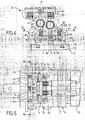
- the figure 1 is a schematic view of the assembly of a leveling installation.
- the figure 2 is an overview, from the side, of a superior planing crew.
- the figure 3 is a detail view, in axial section, of one end of the upper planing crew.
- the figure 4 is a side view of the two planing crews.
- the figure 5 is a horizontal sectional view along line VV of the figure 4 .
- the figure 1 schematically shows the conventional layout of a leveling installation comprising for example two flexion units F1-F2 and a tile correction device T, associated with deflection rollers D and adjustable in height, in order to define a corrugated path of the strip M that runs between the successive rollers in a longitudinal direction parallel to the plane of the figure 1 .
- the strip is put under tension by known means such as so-called "S-roll” tensioning rollers placed upstream and downstream.
- the figure 1 shows, for example, the downstream tensioner device S.
- Each bending unit comprises two planing crews, respectively lower E and upper E 'longitudinally offset and each having, usually, an active cylinder A associated with two intermediate rollers I which are supported on three rows of support rollers G when the cylinder active A is applied to the strip in the planing position shown on the figure 1 by vertical displacement of the frame C, for example, by means of jacks or screws not shown.
- the transverse frame of the upper crew E ' is rotatably mounted about a horizontal axis, according to a provision subject to the FR-A-2,659,254 from the same company, which makes it possible to turn up the entire crew to facilitate disassembly and replacement of cylinders and rollers.
- the active cylinder A and the intermediate rollers I bear on each other and on the rollers G only in the planing position and that is why they are carried with play by the transverse frame C and are only held laterally by axial stops.
- the active cylinder 2 is provided, at its opposite ends, with two journals 3, 3 'centered on the axis 20 of the cylinder and rotatably mounted, by means of bearings 30, 30', on two support pieces 4, 4 'in the way shown in more detail on the figures 3 , 4 and 5 .
- each support piece 4 forms a sort of chock centered on a radial plane P passing through the axis 20 of the active cylinder 2 and comprises an arm 41 mounted to slide radially on a guide foot 5 extending towards the strip from the frame 1, and a box-shaped portion 40 fixed to the end of the arm 41 opposite the frame, and in which is inserted the bearing 30 of the pin 3.
- each support piece 4 of one end of the active cylinder 2 is associated with return means 6 for applying the active cylinder 2 to its support members which consist, in the example shown, of two intermediate rollers 7, 7 ', held axially between the two guide feet 5, 5' and resting on three rows of support rollers 70 rotatably mounted on the transverse frame 1.
- each support piece 4, 4 ' is provided, on the side of the frame 1, with a sole 44 on which at least two springs 6 spaced apart symmetrically on either side of the radial plane P and bearing , in the opposite direction, on the chassis 1.
- each spring 6 is threaded onto a bushing 61 passing through an orifice of the soleplate 44 of the chock 4 and fixed on the chassis 1 by an axial screw 62, the bushing 61 comprising a compression flange 63 of the spring 6.
- Each chock 4, 4 ' is thus mounted to slide radially on at least two bushes 61 and pushed towards the frame 1 by the springs 6 compressed between the flanges 63 and the flange 44 which extends parallel to the base 51, at a low distance from it.
- the two chocks 4, 4 'supporting the ends of the active roller 2 are thus pushed towards the transverse frame 1 by applying the active cylinder on the intermediate rollers 7, 7' which bear on the rollers 70.
- the intermediate rollers 7 are not carried by bearings but simply held laterally between two axial abutments each consisting of a ceramic chip 71 mounted in a housing 72 fixed by a rear extension 73 on the guide foot 5.
- the guide foot 5 comprises two spaced apart amounts 52 carrying the slides 50, between which extends a crossbar 54 provided with two recesses 53 in which are threaded the extensions 73 of the two stops 71 of centering, respectively, of the two intermediate rollers 7, 7 '.
- Each housing 72 is held by a clamping screw engaging in a threaded bore of the extension 73 which is slidably mounted in the housing 53 parallel to the bisecting plane of the two rows of rollers 70 on which it is supported, with a clearance allowing slight adjustments of the intermediate roll.
- the active cylinder 2 when the active cylinder 2 is applied by the springs 6 to the support rollers 7, the latter can move slightly, parallel to themselves so as to be applied on the support rollers 70.
- the active cylinder 2 is subject to wear and must be replaced.
- the bases 51 of the two guide feet 5 carrying the two support pieces 4 are slidably mounted on the transverse frame 1, parallel to the axes of the cylinders.
- each base 51 is provided with a central groove which engages on a rectilinear boss 11 of the transverse frame 1.
- it is provided with two longitudinal housings 12 inside which are mounted sliding, respectively, two strips 13 connected to the base 51 by screws 14 which, after sliding, to block the base 51 in the chosen position.
- each pin 3 of the active cylinder consists of two parts engaging one in the other and secured by a screw 34, respectively a pivot 31 fixed to the end of the active cylinder 2, in the axis of this, and a shaft end 32 threaded into the bearing 30 and, therefore, axially secured to the support part 4 and the guide foot 5.
- the pivot 31 and the shaft end 32 are provided with conical conical portions respectively formed recessed and projecting, and engaging one into the other to ensure both the centering and the rotational drive of the active cylinder 2, one of the shaft ends 32, for example the one on the left on the figure 3 , being provided with a tip 33 on which is applied a rotational torque produced by a motor means not shown.
- each chock 4, 4 'of a trunnion 3, 3' of the active cylinder 2 is equipped with a cylinder spacing means constituted, in the embodiment shown in the drawings, of a cam 8 to eccentric profile rotatably mounted on the central rib 41 of the chock 4 about an axis 80.
- a rotation of the eccentric cam 8 about its axis 80 makes it possible to push the sole 44 of each support piece 4, 4 'by increasing the compression of the springs 6.
- the active cylinder 2 thus being slightly spaced from the intermediate rollers 7, 7 ', it is possible to spread laterally the two guide feet 5, 5' with the support pieces 4, 4 'to release the pivots 31 at both ends of the cylinder 2.
- the two guide feet 5 can be moved axially apart with the support pieces 4, 4 ' and the bearings 30, 30 'which drive the shaft ends 32, 32'.
- the transverse frame 1 is rotatably mounted about a horizontal axis 15, according to a provision which is the subject of the French patent FR 2,659,254 already cited. Indeed, before any disassembly operation, it is thus possible to return 180 ° the upper leveling unit E 'so that the active cylinder 2 is placed above its support members and is based on these last when one discards the two ends of the shaft 32, 32 'with the chocks 4, 4'.
- the chocks 4, 4' are tightened so that the conical portions of the pivot 31 and the shaft end 32 engage one into the other. other.
- the cylinder 2 can then be applied to the intermediate rollers 7, 7 'by rotating in the opposite direction the eccentric cams 8 which are provided with a flat face 81, in order to allow the springs 6 to push the sole 44 towards the base 51.
- the spacing (e) between the sole 44 and the base 51 is kept at a minimum value by adjustable stops 64 consisting of screws engaging in threaded bores of the sole 44.
- one of the two journals of each active cylinder 2, for example the left trunnion 3 on the figure 2 is extended by a drive end 33, for example fluted, which can be removably connected to a motor means such as geared motor, pulley and belt or other motion transmission member, according to the general arrangement selected for the machine .
- a motor means 9 indicated schematically on the Figures 1 and 2 , can be arranged on the fixed frame or on the frame of each planing equipment E, E 'and removably connected to the active cylinder 2, 2', by a telescopic double cardan extension 36 for transmitting the torque to following all the positions of the axis of the active cylinder, according to the diameters of all its support members.
- easy to design means to adjust the rotational speed of the active cylinders of the two planing crews, taking into account their diameters, so as to slave their peripheral speeds to the linear speed of the moving strip.
- This speed of movement can be measured at any moment by a sensor 92, for example from the speed of rotation of the rollers of one of the tensioning units S which, as currently, are placed on either side of the leveling machine in order to put the band in tension.
- the active cylinders 2 can then be started in rotation and they frictionally drive the intermediate rollers and the support rollers.
- the speed of synchronism with the band is reached, one can proceed to the closing of the machine by placing the two crews E, E 'in their planing positions, the docking of the active cylinders on the band being done thus without skating and without risk of marking the product.
- the latter can be driven permanently at an angular speed corresponding to the running speed of the strip, which makes it possible to absorb variations in the planing speed without risk of slipping, even for low friction bands.
- the springs 6 could be replaced by other means.
- the application forces of the active cylinder are not the same for the lower equipment E and for the upper equipment E 'whose weight must be compensated.
- the chocks of the upper active cylinder are advantageously associated with two pairs of springs symmetrical with respect to the radial plane P, on the one hand the springs 60 which exert only the application pressure necessary for the rotational drive of the cylinder and rollers intermediate, and secondly, two springs 65 which are tared so as to take up the weight of the active cylinder 2 with its two chocks 4, 4 ', its drive means 36 and, in a general manner, all the organs which are not worn directly by the chassis.
Landscapes
- Mechanical Engineering (AREA)
- Engineering & Computer Science (AREA)
- Metal Rolling (AREA)
- Soil Working Implements (AREA)
- Reduction Rolling/Reduction Stand/Operation Of Reduction Machine (AREA)
- Casting Or Compression Moulding Of Plastics Or The Like (AREA)
- Manufacture Of Alloys Or Alloy Compounds (AREA)
- Iron Core Of Rotating Electric Machines (AREA)
- Coating With Molten Metal (AREA)
- Straightening Metal Sheet-Like Bodies (AREA)
- Wire Processing (AREA)
- Orthopedics, Nursing, And Contraception (AREA)
- Replacement Of Web Rolls (AREA)
- Folding Of Thin Sheet-Like Materials, Special Discharging Devices, And Others (AREA)
Abstract
Description
L'invention a pour objet une machine de planage utilisable, en particulier, dans une installation de planage sous traction d'une bande métallique et couvre également le procédé mis en oeuvre.The subject of the invention is a leveling machine that can be used, in particular, in a tensile planing installation of a metal strip and also covers the process used.
Le document
Dans les différents secteurs de la métallurgie et, en particulier, pour la production de tôles métalliques, on utilise habituellement des machines de planage pour éliminer autant que possible les défauts de planéité apparaissant à la suite du laminage.In the different sectors of metallurgy and, in particular, for the production of metal sheets, planing machines are usually used to eliminate as much as possible the unevennesses appearing as a result of rolling.
Comme le montre schématiquement la
Comme le montre la
D'autres configurations d'installations peuvent, cependant, être utilisées selon le domaine d'application.Other configurations of installations may, however, be used depending on the field of application.
Chaque équipage de planage comprend un châssis transversal, mobile verticalement dans le bâti et portant un cylindre de planage, appelé cylindre actif, monté rotatif autour d'un axe transversal à la direction de défilement. Pour le planage, le cylindre actif est de faible diamètre, et doit donc prendre appui sur des organes de soutien constitués, le plus souvent, de deux rouleaux intermédiaires reposant eux-mêmes sur trois rangées de galets.Each leveling unit comprises a transverse frame, movable vertically in the frame and carrying a leveling cylinder, called active cylinder, rotatably mounted about an axis transverse to the scroll direction. For leveling, the active cylinder is of small diameter, and must therefore be supported on support members consisting, in most cases, of two intermediate rollers themselves resting on three rows of rollers.
La transmission des efforts et le centrage en rotation se font par application des cylindres actifs sur les rouleaux intermédiaires et les galets d'appui qui sont seuls fixés sur le châssis transversal.The transmission of the forces and the centering in rotation are done by application of the active cylinders on the intermediate rollers and the support rollers which are only fixed on the transverse frame.
En effet, pour réaliser l'effet souhaité de flexion-traction, les cylindres actifs de planage doivent avoir un diamètre assez faible et tournent donc à une très grande vitesse, ce qui entraîne une usure relativement rapide de leurs faces externes. Les cylindres actifs et, éventuellement, les rouleaux intermédiaires doivent donc être remplacés périodiquement.Indeed, to achieve the desired effect of flexion-traction, the active planishing cylinders must have a relatively small diameter and therefore rotate at a very high speed, resulting in relatively rapid wear of their outer faces. The active cylinders and possibly the intermediate rollers must therefore be replaced periodically.
Pour cela, on utilise habituellement un dispositif de démontage qui permet de retirer l'ensemble de l'équipage de planage nécessitant un entretien pour l'écarter latéralement sur un côté de la machine, la bande métallique pouvant rester dans la machine, soit à l'arrêt, soit en cours de défilement. En effet, pour un simple changement des cylindres actifs ou tout autre entretien de courte durée, il est préférable d'arrêter seulement la planeuse pour l'ouvrir et procéder au remplacement des cylindres sans arrêter le défilement de la bande dans la section de traitement.For this purpose, a disassembly device is usually used which makes it possible to remove the assembly of the planing unit requiring maintenance and to spread it laterally on one side of the machine, the metal strip being able to remain in the machine, ie 'stop, either while scrolling. Indeed, for a simple change of the active cylinders or any other short-term maintenance, it is preferable to stop only the planeuse to open it and replace the cylinders without stopping the running of the band in the processing section.
De telles opérations doivent donc être effectuées rapidement et c'est pourquoi, habituellement, les cylindres actifs et les rouleaux intermédiaires sont simplement maintenus à leurs extrémités par des butées axiales, généralement, en matériau céramique, qui reprennent les poussées axiales apparaissant lors du planage de la bande. L'ensemble doit cependant être monté de façon à rester solidaire du châssis transversal dans les phases d'ouverture et de fermeture de la machine, hors planage, ainsi que lors de la manipulation des châssis.Such operations must therefore be performed quickly and that is why, usually, the active cylinders and the intermediate rollers are simply held at their ends by axial abutments, usually made of ceramic material, which take up the axial thrusts occurring during the planing of the band. The assembly must however be mounted so as to remain attached to the transverse frame in the opening and closing phases of the machine, out of planing, as well as during the handling of the chassis.
Auparavant, le planage était réalisé dans des machines séparées, la bande se déroulant à partir d'une bobine placée en amont pour être réenroulée en aval. Cependant, il est maintenant nécessaire d'installer des machines à planer dans des lignes continues utilisées, en particulier, pour le recuit ou la galvanisation à chaud de la bande.Previously, the planing was done in separate machines, the band running from a coil placed upstream to be rewound downstream. However, it is now necessary to install planing machines in continuous lines used, in particular, for annealing or hot-dip galvanizing the strip.
Dans de telles lignes, les bobines sont soudées bout à bout à l'entrée de la ligne, la bande étant recoupée en bobines à la sortie. Des accumulateurs de bandes sont donc placés, respectivement, en amont et en aval pour assurer un défilement à vitesse constante de la bande dans une section centrale de traitement pendant l'arrêt nécessaire à l'entrée pour le soudage ou à la sortie pour le cisaillage. Les planeuses sont, normalement, installées dans cette section centrale à vitesse sensiblement constante afin d'obtenir la régularité souhaitée des paramètres qualités du produit.In such lines, the coils are welded end to end at the line entrance, the strip being cut into coils at the outlet. Tape accumulators are therefore placed, respectively, upstream and downstream to ensure a constant speed of travel of the strip in a central processing section during the stop required for the inlet for welding or the exit for shearing. . The planers are normally installed in this central section at a substantially constant speed in order to obtain the desired regularity of the quality parameters of the product.
Cependant, la soudure entre deux bobines successives constitue, généralement, une surépaisseur qui risque de détériorer les cylindres de planage. Pour éviter cet inconvénient, il est préférable d'ouvrir la planeuse en écartant les cylindres de planage au moment du passage de la soudure et en les ramenant ensuite au contact de la bande. L'ensemble des cylindres actifs, des rouleaux intermédiaires et des galets d'appui est alors de nouveau entraîné par friction lors de l'accostage de l'équipement sur la bande et il en résulte, inévitablement, un patinage dû à l'inertie en rotation des différents cylindres et galets pendant quelques secondes qui peuvent, cependant, correspondre à plusieurs dizaines de mètres de bande, compte tenu de la vitesse de défilement.However, the welding between two successive coils is usually an extra thickness that may deteriorate the planing rolls. To avoid this disadvantage, it is preferable to open the planer by spreading the planing rolls at the time of the passage of the weld and then bringing them into contact with the strip. The set of active cylinders, intermediate rollers and support rollers is then again dragged by friction during the docking of the equipment on the belt and this inevitably results in slippage due to inertia. rotation of the various cylinders and rollers for a few seconds which may, however, correspond to several tens of meters of tape, given the speed of scrolling.
Généralement, dans une ligne de recuit continu ou de galvanisation à chaud, un tel patinage est toléré car les défauts par griffures, piqûres ou les défauts de rugosité qui peuvent en résulter sont peu visibles ou du moins, pas rédhibitoires pour des aciers ordinaires.Generally, in a continuous annealing or hot-dip galvanizing line, such slippage is tolerated because the defects by scratching, pitting or roughness defects that may result therefrom are not very visible or at least not prohibitive for ordinary steels.
Cependant, on cherche maintenant à traiter dans des lignes continues d'autres types d'aciers pour lesquels la surface est plus fragile et son aspect plus important, comme par exemple les aciers inoxydables. En outre, de tels aciers présentent souvent un coefficient de frottement réduit, c'est-à-dire une capacité moindre à entraîner par friction l'ensemble des cylindres et galets, ce qui augmente le risque de patinage.However, it is now sought to treat in continuous lines other types of steels for which the surface is more fragile and its more important appearance, such as stainless steels. In addition, such steels often have a reduced coefficient of friction, that is to say a lower ability to frictionally drive all cylinders and rollers, which increases the risk of slipping.
Pour éviter cet inconvénient, on a proposé, dans le document
Une telle disposition permet de placer le moteur et l'embrayage sur le châssis de l'équipage de planage dans une position écartée du plan de défilement de la bande mais présente certains inconvénients.Such an arrangement makes it possible to place the motor and the clutch on the chassis of the leveling equipment in a position separated from the plane of travel of the band but presents certain drawbacks.
En effet, le couple de rotation est transmis au cylindre actif uniquement par friction et cet effet dépend de la pression d'application des organes tournant les uns sur les autres. Pour l'équipage inférieur, cette pression d'application correspond simplement au poids du cylindre actif et des rouleaux intermédiaires, tant que le cylindre actif n'est pas appliqué sur la bande.Indeed, the torque is transmitted to the active cylinder only by friction and this effect depends on the application pressure of the rotating members on each other. For the lower crew, this application pressure is simply the weight of the active cylinder and the intermediate rollers, as long as the active cylinder is not applied to the belt.
En revanche, pour l'équipage supérieur, le cylindre actif doit être porté, à ses extrémités, par deux paliers suspendus au châssis de l'équipage par des ressorts qui tirent vers le haut le cylindre actif afin de l'appliquer sur les rouleaux intermédiaires et les galets de soutien.On the other hand, for the upper crew, the active cylinder must be carried at its ends by two bearings suspended from the chassis of the crew by springs which pull up the active cylinder in order to apply it to the intermediate rollers. and the support rollers.
Pour permettre le démontage du cylindre actif, les ressorts sont reliés aux paliers par des crochets amovibles.To allow disassembly of the active cylinder, the springs are connected to the bearings by removable hooks.
Une telle disposition est assez complexe et risque de ne pas garantir une pression d'application suffisante pour l'entraînement par friction des cylindres actifs à la vitesse voulue.Such an arrangement is quite complex and may not guarantee sufficient application pressure for the friction drive of the active rolls at the desired speed.
D'autre part, la vitesse angulaire des galets de soutien sur lesquels est appliqué le couple de rotation doit être réglée en fonction du rapport des diamètres desdits galets, des rouleaux intermédiaires et du cylindre actif afin que la vitesse angulaire de ce dernier corresponde exactement à la vitesse de défilement de la bande. Or, les diamètres de ces différents organes peuvent varier légèrement du fait de l'usure et il faut en tenir compte pour le réglage des vitesses angulaires. De plus, cette usure n'est pas répartie régulièrement sur la longueur des cylindres et il peut donc exister une légère différence de diamètre et, par conséquent, de vitesse périphérique entre les galets successifs de la rangée entraînée en rotation. Cette différence entraîne une usure accrue de certaines parties des rouleaux intermédiaires et des cylindres actifs qui peut se traduire par des défauts sur la bande. L'objectif recherché risque donc de ne pas être atteint.On the other hand, the angular velocity of the support rollers on which the torque is applied must be adjusted according to the ratio of diameters of said rollers, intermediate rollers and the active cylinder so that the angular velocity of the latter corresponds exactly to the speed of the tape. However, the diameters of these different members may vary slightly due to wear and must be taken into account for the adjustment of angular velocities. Moreover, this wear is not evenly distributed over the length of the rolls and there may therefore be a slight difference in diameter and, consequently, in peripheral speed between the successive rollers of the row driven in rotation. This difference results in increased wear of parts of the intermediate rollers and active rolls which can result in defects on the web. The objective sought may therefore not be achieved.
L'invention permet de remédier à ces divers inconvénients grâce à une nouvelle disposition permettant, par des moyens très simples, d'entraîner à coup sûr les cylindres actifs à une vitesse angulaire correspondant à la vitesse de défilement du produit, tout en conservant une possibilité de démontage et remontage facile et rapide des cylindres actifs et, le cas échéant, des rouleaux intermédiaires.The invention overcomes these various drawbacks with a new arrangement allowing, by very simple means, to surely drive the active cylinders at an angular speed corresponding to the speed of travel of the product, while maintaining a possibility easy and quick disassembly and reassembly of the active cylinders and, if necessary, intermediate rollers.
L'invention est définie dans les revendications indépendantes 1 et 22.The invention is defined in independent claims 1 and 22.
L'invention s'applique donc, d'une façon générale, à une machine de planage comportant au moins deux équipages de planage placés de part et d'autre de la bande et comportant chacun un cylindre actif et un ensemble d'organes de soutien montés rotatifs autour de leurs axes sur un châssis transversal, l'ensemble étant déplaçable parallèlement à lui-même entre une position de repos pour laquelle le cylindre actif est écarté de la bande et une position de planage pour laquelle le cylindre actif est appliqué sur la bande en prenant appui, du côté opposé, sur ses organes de soutien, chaque cylindre actif pouvant être entraîné en rotation, avant son application sur la bande, à une vitesse angulaire correspondant sensiblement à la vitesse de défilement de la bande.The invention therefore applies, in a general manner, to a leveling machine comprising at least two leveling equipments placed on either side of the strip and each comprising an active cylinder and a set of support members. mounted rotatably about their axes on a transverse frame, the assembly being movable parallel to itself between a rest position for which the active cylinder is spaced from the strip and a leveling position for which the active cylinder is applied to the band bearing on the support side, on the opposite side, each active cylinder can be rotated, before its application on the band, at an angular speed corresponding substantially to the speed of travel of the band.
Conformément à l'invention, l'entraînement en rotation de chaque cylindre actif est déterminé par application directe d'un couple de rotation sur une extrémité dudit cylindre, à une vitesse angulaire asservie à la vitesse de défilement de la bande.According to the invention, the rotational drive of each active cylinder is determined by direct application of a rotational torque on one end of said cylinder, at an angular speed controlled by the running speed of the strip.
A cet effet, chaque cylindre actif est porté, à chacune de ses extrémités, par un tourillon de centrage monté rotatif autour de l'axe du cylindre, sur une pièce de support montée coulissante sur le châssis transversal de l'équipage parallèlement à un plan radial passant par l'axe dudit cylindre actif, les positions par rapport audit châssis des deux pièces de support pouvant être réglées par coulissement radial pour le déplacement du cylindre actif, parallèlement à son axe, entre une position d'application sur ses organes de soutien et une position écartée, et l'un des tourillons de centrage de chaque cylindre actif est relié à un moyen d'application directe d'un couple de rotation sur ledit tourillon.For this purpose, each active cylinder is carried at each of its ends by a centering pin rotatably mounted about the axis of the cylinder, on a support member slidably mounted on the transverse frame of the crew parallel to a plane. radial axis passing through the axis of said active cylinder, the positions relative to said frame of the two support pieces being adjustable by radial sliding for the displacement of the active cylinder, parallel to its axis, between a application position on its support members and a spaced position, and one of the centering pins of each active cylinder is connected to a means for direct application of a rotational torque on said pin.
De façon particulièrement avantageuse, chaque pièce de support d'un cylindre actif, comporte une première partie en forme de boîtier cylindrique, dans laquelle est monté un palier de support rotatif du cylindre actif, centré sur un plan radial passant par l'axe dudit cylindre, et une seconde partie formant un bras monté coulissant sur une glissière ménagée sur un pied de guidage fixé sur le châssis transversal de l'équipage de planage. De plus, chaque pièce de support coulissante est associée à un moyen de rappel prenant appui, dans un sens sur la pièce de support et dans l'autre sur le châssis transversal, pour l'application du cylindre actif sur ses organes de soutien.Particularly advantageously, each support part of an active cylinder comprises a first portion in the form of a cylindrical housing, in which is mounted a rotatable support bearing of the active cylinder, centered on a radial plane passing through the axis of said cylinder. , and a second portion forming an arm slidably mounted on a slide formed on a guide foot fixed to the transverse frame of the leveling crew. In addition, each piece of sliding support is associated with a return means bearing in one direction on the support piece and in the other on the transverse frame, for the application of the active cylinder on its support members.
De préférence, chaque pièce de support comporte un moyen d'appui sur le châssis, constitué avantageusement d'une came montée rotative entre au moins deux positions, respectivement une position écartée du châssis, permettant l'application du cylindre actif sur ses organes de soutien, grâce au moyen de rappel prenant appui sur ladite pièce de support et une position d'appui sur le châssis pour repousser la pièce de support contre l'action du moyen de rappel.Preferably, each support member comprises a support means on the frame, advantageously constituted by a cam mounted rotatably between at least two positions, respectively a position spaced from the frame, allowing the application of the active cylinder on its support members , thanks to the biasing means bearing on said support member and a bearing position on the frame to push the support member against the action of the biasing means.
Dans un mode de réalisation préférentiel, chaque pièce de support comporte une partie d'appui munie d'au moins un orifice de passage d'au moins une tige de guidage fixée par une première extrémité sur le châssis transversal et s'étendant, de l'autre côté de la partie d'appui de la pièce de support, jusqu'à une seconde extrémité sur laquelle est ménagée une bride d'appui d'un moyen élastique comprimé entre ladite bride et la partie d'appui de la pièce de support.In a preferred embodiment, each support member comprises a bearing portion provided with at least one through hole of at least one guide rod fixed by a first end to the transverse frame and extending, on the other side of the support portion of the support piece, to a second end on which is formed a support flange of a resilient means compressed between said flange and the support portion of the support piece .
Selon une autre caractéristique préférentielle, chaque pièce de support d'un cylindre actif porte un palier de centrage avec une cage interne rotative dans laquelle est enfilée un tourillon de support fixé sur l'extrémité du cylindre actif, dans l'axe de celui-ci, l'un des deux tourillons étant prolongé vers l'extérieur par un embout d'entraînement relié à un moyen de commande de la rotation du tourillon avec le cylindre actif, autour de son axe.According to another preferred feature, each support part of an active cylinder carries a centering bearing with a rotating internal cage in which is threaded a support pin fixed on the end of the active cylinder, in the axis thereof. , one of the two journals being extended outwardly by a drive end connected to a means for controlling the rotation of the journal with the active cylinder, about its axis.
Avantageusement, chacun des deux tourillons de support du cylindre actif forme un bout d'arbre muni, du côté du cylindre actif, d'un moyen de liaison amovible avec le cylindre actif, ledit bout d'arbre étant déplaçable axialement entre une position resserrée de liaison avec le cylindre, pour le support rotatif de ce dernier et une position écartée, désolidarisée de l'extrémité du cylindre, pour le démontage de ce dernier, ce moyen de liaison pouvant être constitué de deux parties de formes conjuguées ménagées respectivement sur le tourillon et l'extrémité du cylindre et s'engageant l'une sur l'autre par déplacement axial du tourillon d'une position écartée à une position resserrée.Advantageously, each of the two support journals of the active cylinder forms a shaft end provided, on the side of the active cylinder, with a detachable connecting means with the active cylinder, said shaft end being axially displaceable between a constricted position of connection with the cylinder, for the rotary support of the latter and a spaced apart position, disengaged from the end of the cylinder, for disassembly of the latter, the connecting means being able to consist of two parts of conjugate forms formed respectively on the trunnion; and the end of the cylinder and engaging one another by axial displacement of the journal from a spaced apart position to a constricted position.
Selon une autre disposition particulièrement avantageuse, au moins la pièce de support du tourillon d'entraînement de chaque cylindre actif est montée coulissante parallèlement à un plan radial passant par l'axe dudit cylindre, sur un pied de guidage solidaire d'une embase montée coulissante sur le châssis transversal, parallèlement à l'axe du cylindre actif, entre une position resserrée des deux pièces de support pour l'engagement des extrémités du cylindre actif sur les paliers de centrage et une position écartée de dégagement des extrémités du cylindre actif, pour le démontage de ce dernier, le châssis transversal étant muni de moyens de fixation de l'embase du pied de guidage de chaque pièce de support dans la position resserrée d'engagement des extrémités du cylindre actif sur les paliers de centrage.According to another particularly advantageous arrangement, at least the support member of the driving pin of each active cylinder is slidably mounted parallel to a radial plane passing through the axis of said cylinder, on a guide foot integral with a sliding mounted base on the transverse frame, parallel to the axis of the active cylinder, between a constricted position of the two support pieces for engaging the ends of the active cylinder on the centering bearings and a spaced apart position of the ends of the active cylinder, for the disassembly of the latter, the transverse frame being provided with means for fixing the base of the guide foot of each support piece in the constricted position of engagement of the ends of the active cylinder on the centering bearings.
Grâce aux dispositions selon l'invention, dans la position de repos de l'équipage de planage, le cylindre actif peut être écarté de ses rouleaux de soutien par les deux cames, afin d'être démonté puis, après remontage entre les deux tourillons, il est repoussé par les deux pièces de support dans le sens opposé de façon à prendre appui à l'avance sur ses organes de soutien. Dans cette position, il est entraîné en rotation à une vitesse périphérique correspondant à la vitesse de défilement de la bande, en entraînant également les organes de soutien, de telle sorte que la mise en contact avec la bande, dans la position de planage, peut se produire sans risque de patinage et, par conséquent, de détérioration de la qualité superficielle du produit.Thanks to the provisions according to the invention, in the rest position of the planing equipment, the active cylinder can be separated from its support rollers by the two cams, in order to be disassembled and, after reassembly between the two journals, it is pushed back by the two support pieces in the opposite direction so as to bear in advance on its support members. In this position, it is rotated at a peripheral speed corresponding to the running speed of the strip, also driving the support members, so that the contact with the strip, in the planing position, can occur without risk of slippage and, therefore, deterioration of the surface quality of the product.
Cependant, cette application du cylindre actif sur ses organes de soutien peut être maintenue dans la position de repos de l'équipage de planage, le cylindre actif étant écarté de ses organes de soutien seulement en cas de besoin pour démontage et/ou remplacement.However, this application of the active cylinder on its support members can be maintained in the rest position of the flight crew. planing, the active cylinder being removed from its support members only in case of need for disassembly and / or replacement.
Par ailleurs, du fait que le couple de rotation est appliqué directement sur le cylindre actif, la vitesse angulaire de rotation de celui-ci autour de son axe peut être asservie à la vitesse de défilement de la bande et cela, non seulement dans la position de repos de l'équipage de planage mais également, au cours du planage, dans la position de travail de l'équipage.Moreover, because the rotational torque is applied directly to the active cylinder, the angular speed of rotation thereof around its axis can be slaved to the running speed of the tape and this, not only in the position rest of the planing crew but also, during the planing, in the working position of the crew.
On évite ainsi le risque de patinage, non seulement lors de l'accostage après un arrêt du planage, mais aussi pendant le planage, par exemple en cas de variation brusque de la vitesse de défilement dans la section de planage, l'inertie des rouleaux et des galets de soutien étant compensée du fait que le couple de rotation à vitesse asservie est appliqué directement sur le cylindre actif qui entraîne par friction ses organes de soutien.This avoids the risk of skidding, not only when docking after a stop planing, but also during the planing, for example in case of abrupt variation of the speed of travel in the planing section, the inertia of the rollers and support rollers being compensated because the slave speed rotational torque is applied directly to the active cylinder which frictionally drives its support members.
D'autres caractéristiques avantageuses entrant dans le cadre de protection de l'invention, apparaîtront dans la description qui va suivre d'un mode de réalisation particulier, donné à titre d'exemple et représenté sur les dessins annexés.Other advantageous features within the scope of protection of the invention will appear in the following description of a particular embodiment, given by way of example and shown in the accompanying drawings.
La
La
La
La
La
Comme indiqué plus haut, la
Pour réaliser le planage, la bande est mise sous traction par des moyens connus tels que des rouleaux tensionneurs dits « rouleaux en S » placés en amont et en aval. La
Chaque unité de flexion comprend deux équipages de planage, respectivement inférieur E et supérieur E' décalés longitudinalement et comportant chacun, habituellement, un cylindre actif A associé à deux rouleaux intermédiaires I qui prennent appui sur trois rangées de galets d'appui G lorsque le cylindre actif A est appliqué sur la bande dans la position de planage représentée sur la
Sur la
Avantageusement, dans l'exemple représenté sur la
Comme on l'a indiqué plus haut, dans les dispositions utilisées habituellement, le cylindre actif A et les rouleaux intermédiaires I, ne prennent appui les uns sur les autres et sur les galets G que dans la position de planage et c'est pourquoi ils sont portés avec jeu par le châssis transversal C et sont seulement maintenus latéralement par des butées axiales.As indicated above, in the arrangements usually used, the active cylinder A and the intermediate rollers I, bear on each other and on the rollers G only in the planing position and that is why they are carried with play by the transverse frame C and are only held laterally by axial stops.
Dans l'invention, au contraire, comme le montrent les
Dans cette disposition, chaque pièce de support 4 forme une sorte d'empoise centrée sur un plan radial P passant par l'axe 20 du cylindre actif 2 et comporte un bras 41 monté coulissant radialement sur un pied de guidage 5 s'étendant vers la bande à partir du châssis 1, et une partie en forme de boîtier 40, fixée à l'extrémité du bras 41 opposée au châssis, et dans laquelle est inséré le palier 30 du tourillon 3.In this arrangement, each
D'autre part, chaque pièce de support 4 d'une extrémité du cylindre actif 2 est associée à des moyens de rappel 6 permettant d'appliquer le cylindre actif 2 sur ses organes de soutien qui sont constitués, dans l'exemple représenté, de deux rouleaux intermédiaires 7, 7', maintenus axialement entre les deux pieds de guidage 5, 5' et reposant sur trois rangées de galets d'appui 70 montés rotatifs sur le châssis transversal 1.On the other hand, each
A cet effet, chaque pièce de support 4, 4' est munie, du côté du châssis 1, d'une semelle 44 sur laquelle prennent appui au moins deux ressorts 6 écartés symétriquement de part et d'autre du plan radial P et prenant appui, dans le sens opposé, sur le châssis 1.For this purpose, each
Comme le montrent les
Chaque empoise 4, 4' est ainsi montée coulissante radialement sur au moins deux douilles 61 et repoussée vers le châssis 1 par les ressorts 6 comprimés entre les brides 63 et la semelle 44 qui s'étend parallèlement à l'embase 51, à une faible distance de celle-ci.Each
Les deux empoises 4, 4' de support des extrémités du rouleau actif 2 sont ainsi repoussées vers le châssis transversal 1 en appliquant le cylindre actif sur les rouleaux intermédiaires 7, 7' qui prennent appui sur les galets 70.The two
Comme habituellement, les rouleaux intermédiaires 7 ne sont pas portés par des paliers mais simplement maintenus latéralement entre deux butées axiales constituées chacune d'une pastille en céramique 71 montée dans un boîtier 72 fixé par un prolongement arrière 73 sur le pied de guidage 5. A cet effet, le pied de guidage 5 comporte deux montants écartés 52 portant les glissières 50, entre lesquels s'étend une traverse 54 munie de deux évidements 53 dans lesquels s'enfilent les prolongements 73 des deux butées 71 de centrage, respectivement, des deux rouleaux intermédiaires 7, 7'.As usual, the
Chaque boîtier 72 est maintenu par une vis de serrage s'engageant dans un alésage fileté du prolongement 73 qui est monté coulissant dans le logement 53 parallèlement au plan bissecteur des deux rangées de galets 70 sur lesquels il s'appuie, avec un jeu permettant de légers ajustements du rouleau intermédiaire.Each
Ainsi, lorsque le cylindre actif 2 est appliqué par les ressorts 6 sur les rouleaux de soutien 7, ces derniers peuvent se déplacer légèrement, parallèlement à eux-mêmes de façon à venir s'appliquer sur les galets d'appui 70.Thus, when the
Par ailleurs comme on l'a indiqué plus haut, le cylindre actif 2 est soumis à usure et doit pouvoir être remplacé. Pour cela, les embases 51 des deux pieds de guidage 5 portant les deux pièces de support 4 sont montées coulissantes sur le châssis transversal 1, parallèlement aux axes des cylindres.Moreover, as indicated above, the
A cet effet, comme le montrent les
Par ailleurs, chaque tourillon 3 du cylindre actif est constitué de deux parties s'engageant l'une dans l'autre et solidarisées par une vis 34, respectivement un pivot 31 fixé à l'extrémité du cylindre actif 2, dans l'axe de celui-ci, et un bout d'arbre 32 enfilé dans le palier 30 et, par conséquent, solidaire axialement de la pièce de support 4 et du pied de guidage 5.Furthermore, each
Dans le mode de réalisation préférentiel représenté sur la
Cependant, pour permettre le démontage du cylindre actif 2, il faut supprimer la pression d'application de celui-ci sur les rouleaux intermédiaires 7, 7'.However, to allow disassembly of the
A cet effet, chaque empoise 4, 4' d'un tourillon 3, 3' du cylindre actif 2 est équipée d'un moyen d'écartement du cylindre constitué, dans l'exemple de réalisation représenté sur les dessins, d'une came 8 à profil excentré montée rotative sur la nervure centrale 41 de l'empoise 4 autour d'un axe 80. Ainsi, comme le montre la
Ainsi, après avoir débloqué les embases 51 en dévissant les vis 14 et désolidarisé les deux parties 31, 32 de chaque tourillon 3 en dévissant les vis 34, on peut écarter axialement les deux pieds de guidage 5 avec les pièces de support 4, 4' et les paliers 30, 30' qui entraînent les bouts d'arbre 32, 32'.Thus, after having unlocked the
Dans le cas de l'équipage de planage inférieur E, représenté sur les
En cas de besoin, on peut aussi enlever et remplacer les rouleaux intermédiaires 7, 7' qui reposent sur les galets d'appui 70.If necessary, it is also possible to remove and replace the
Dans le cas de l'équipage de planage supérieur E' représenté sur la
Après remplacement du cylindre actif 2 et, éventuellement des rouleaux intermédiaires 7, 7', les empoises 4, 4' sont resserrées de façon que les parties coniques du pivot 31 et du bout d'arbre 32 s'engagent l'une dans l'autre. Le cylindre 2 peut alors être appliqué sur les rouleaux intermédiaires 7, 7' en tournant dans l'autre sens les cames excentrées 8 qui sont munies d'une face plane 81, afin de permettre aux ressorts 6 de repousser la semelle 44 vers l'embase 51.After replacing the
Pour éviter le blocage de la came 8, l'espacement (e) entre la semelle 44 et l'embase 51 est maintenu à une valeur minimale par des butées réglables 64 constituées de vis s'engageant dans des alésages filetés de la semelle 44.To prevent jamming of the
Comme habituellement, ces opérations peuvent être effectuées sur chaque équipage de planage, dans une position d'entretien écartée de la machine et l'ensemble de l'équipage, avec le châssis transversal, est ensuite replacé en position de travail à l'intérieur du bâti.As usual, these operations can be performed on each leveling unit, in a maintenance position spaced from the machine and the entire crew, with the transverse frame, is then returned to the working position inside the machine. frame.
Par ailleurs, comme indiqué plus haut, l'un des deux tourillons de chaque cylindre actif 2, par exemple le tourillon de gauche 3 sur la
D'autre part, des moyens faciles à concevoir permettent de régler la vitesse de rotation des cylindres actifs des deux équipages de planage, en tenant compte de leurs diamètres, de façon à asservir leurs vitesses périphériques à la vitesse linéaire de la bande en défilement. Cette vitesse de défilement peut être mesurée à chaque instant, par un capteur 92, par exemple à partir de la vitesse de rotation des rouleaux de l'un des blocs tensionneurs S qui, comme actuellement, sont placés de part et d'autre de la machine de planage afin de mettre la bande en traction.On the other hand, easy to design means to adjust the rotational speed of the active cylinders of the two planing crews, taking into account their diameters, so as to slave their peripheral speeds to the linear speed of the moving strip. This speed of movement can be measured at any moment by a
Les dispositions qui viennent d'être décrites permettent d'apporter une solution simple et relativement économique à l'ensemble des problèmes exposés plus haut et, en particulier, d'éviter les effets de patinage risquant de détériorer l'état de surface du produit, tout en facilitant l'entretien des équipages de planage.The arrangements just described make it possible to provide a simple and relatively economical solution to all of the problems set out above and, in particular, to avoid the effects of skidding which could deteriorate the surface condition of the product. while facilitating the maintenance of planing crews.
En effet, du fait qu'un couple de rotation peut être appliqué directement sur l'un des tourillons de chaque cylindre actif, la vitesse angulaire de celui-ci peut être réglée avec précision et, en particulier, asservie à la vitesse de défilement de la bande, de façon que les deux vitesses soient maintenues identiques à chaque instant.Indeed, because a rotational torque can be applied directly to one of the journals of each active cylinder, the angular velocity thereof can be adjusted precisely and, in particular, slaved to the scroll speed of the band, so that the two speeds are kept identical at each moment.
Par ailleurs, l'entraînement direct en rotation de chaque cylindre par un tourillon relié de façon amovible au cylindre 2 facilite le démontage et le remontage du cylindre.Furthermore, the direct drive in rotation of each cylinder by a pin connected detachably to the
En effet, après avoir placé l'ensemble d'un équipage de planage dans sa position de repos, écartée de la bande, il est possible, par simple rotation des cames 8, de repousser les deux pièces de support 4, 4' avec le cylindre 2. Les deux pièces de support 4, 4' sont alors écartés axialement afin de libérer le cylindre 2 qui, dans cette position, est écarté des rouleaux intermédiaires 7, 7' et peut être retiré sans risque de détérioration de sa surface.Indeed, after placing the assembly of a leveling unit in its rest position, separated from the band, it is possible, by simple rotation of the
Après remontage du cylindre actif 2, celui-ci est appliqué de nouveau sur les rouleaux intermédiaires 7 et les galets 70 par rotation des deux cames 8. L'ensemble est serré sous un effort réglé par le tarage des ressorts 6.After reassembly of the
Les cylindres actifs 2 peuvent alors être lancés en rotation et ils entraînent par friction les rouleaux intermédiaires et les galets d'appui. Lorsque la vitesse de synchronisme avec la bande est atteinte, on peut procéder à la fermeture de la machine en plaçant les deux équipages E, E' dans leurs positions de planage, l'accostage des cylindres actifs sur la bande se faisant ainsi sans patinage et sans risque de marquage du produit.The
De plus, même en cours de planage, en raison du contrôle précis et de la possibilité d'asservissement des vitesses angulaires des cylindres actifs, ces derniers peuvent être entraînés en permanence à une vitesse angulaire correspondant à la vitesse de défilement de la bande, ce qui permet d'absorber des variations de la vitesse de planage sans risque de patinage, même pour des bandes à faible coefficient de frottement.Moreover, even during leveling, because of the precise control and the possibility of servocontrolling the angular velocities of the active cylinders, the latter can be driven permanently at an angular speed corresponding to the running speed of the strip, which makes it possible to absorb variations in the planing speed without risk of slipping, even for low friction bands.
Bien entendu, l'invention ne se limite pas aux détails du mode de réalisation qui vient d'être décrit à titre de simple exemple, d'autres variantes pouvant être imaginées dans le cadre de protection de l'invention, telle que définie par les revendicatiions.Of course, the invention is not limited to the details of the embodiment that has just been described as a simple example, other variants that can be imagined in the context of protection of the invention, as defined by the revendicatiions.
C'est ainsi que des moyens équivalents pourraient être employés pour le montage amovible des tourillons d'un cylindre actif dans leurs paliers, le montage coulissant de ces derniers, à la fois dans le sens axial et dans le sens radial et l'application dudit cylindre sur ses organes de soutien.Thus equivalent means could be used for the removable mounting of the journals of an active cylinder in their bearings, the sliding assembly thereof, both in the axial direction and in the radial direction and the application of said cylinder on his support organs.
En particulier, les ressorts 6 pourraient être remplacés par d'autres moyens. En outre, il y a lieu de noter que les efforts d'application du cylindre actif ne sont pas les mêmes pour l'équipement inférieur E et pour l'équipement supérieur E' dont il faut compenser le poids. C'est pourquoi, comme le montre la
Par ailleurs, dans un mode de réalisation plus simple, seul le tourillon d'entraînement 3 pourrait être relié de façon amovible à l'extrémité du cylindre, l'autre tourillon restant fixé sur le cylindre et pouvant simplement s'engager axialement dans la cage interne du palier correspondant pour le remontage du cylindre, le pied de guidage de la pièce 4' de support du palier étant alors fixé sur le châssis.Moreover, in a simpler embodiment, only the
Les signes de référence insérés après les caractéristiques techniques mentionnées dans les revendications, ont pour seul but de faciliter la compréhension de ces dernières et n'en limitent aucunement la portée.The reference signs inserted after the technical features mentioned in the claims, are intended only to facilitate the understanding of the latter and in no way limit the scope.
Claims (24)
- Machine for straightening metal bands• comprising control means of the travel under tension of the strip along a longitudinal direction and along a travel plane, at least two straightening trains (E, E') located on both sides of the strip (M) and each comprising an active cylindrical roll (A, 2) and a set (I, 7) of support units assembled rotating on a transverse frame (C, 1), around rotation axes parallel to each other and orthogonal to the direction of travel, and control means of the movement of each straightening train (E, E'), in a parallel to itself, between an at rest position wherein the active roll (A, 2) is spaced out from the strip and a straightening position wherein the active roll rests on the strip by leaning, on the opposite side, against its support units (I, 7), each roll (2) able to be driven spinning, before its resting on the strip (M), at an angular speed corresponding more or less to the travel speed of the strip,• characterized by the fact that- each active roll (2, 2') is carried, at each of its ends, by a centring spindle (3, 3') assembled spinning on the axis of the cylindrical roll, on a bearing chock (4, 4') assembled sliding on the transverse frame (1) of the train (E, E') in a parallel to a radial plane (P) going through the axis of said active roll (2),- the positions in relation to said frame of the two bearing chocks (4, 4') can be set through radial sliding for the moving of the active roll (2), in a parallel to its axis, between a position of leaning against its support units (7, 7') and a spaced out position,and that- each active roll (2, 2') can be driven spinning on its axis by direct exertion of a rotation torque to one of its centring spindle (3).
- Machine for straightening metal bands according to claim 1, characterized by the fact that each bearing chock (4, 4') of an active roll (2) comprises a part (40) shaped like a casing, wherein is assembled a rotating support bearing (30) of the corresponding spindle (3, 3') of the active roll (2), centered on a radial plane (P) going through the axis (20) of said roll (2) and an arm (41) assembled sliding on a guide (50) located on a guiding stand (5) fixed on the transverse frame (1) of the straightening train.
- Machine for straightening metal bands according to anyone of claims 1 and 2, characterized by the fact that each sliding bearing chock (4, 4') is associated to a return mean (6) resting in one direction on the bearing chock (4) and, in the opposite direction, on the transverse frame (1), for the leaning of the active roll (2) against its support units (7, 7').
- Machine for straightening metal bands according to claim 3, characterized by the fact that each bearing chock (4, 4') comprises a mean (8) of resting on the frame (1) to push back the active roll (2), against the action of the return mean (6), in a position of dismantling and of reassembly wherein the active roll (2) is spaced out from its support units (7, 7') or rests freely on them.
- Machine for straightening metal bands according to claim 4, characterized by the fact that the resting mean (8) is a cam assembled spinning on an axis (80) and comprising• a side resting on the frame (1) by spinning on the axis (80), in order to push back the bearing chock (4, 4') against the action of the return mean (6) and• a flat side (81) putting itself, by rotation of the cam (8), into a spaced out position from the frame (1) to allow the leaning of the active roll (2) against its support units (7) thanks to the return means (6).
- Machine for straightening metal bands according to anyone of claims 1 to 5, characterized by the fact that each bearing chock (4) comprises a support part (44) provided with at least one opening giving way to at least one guiding rod (61) fixed by a first end on the transverse frame (1) and stretching, on the other side of the support part (44) of the bearing chock, up to a second end on which is located a thrust flange (63) for a springy return mean (6) compressed between said thrust flange (63) and the support part (44) of the bearing chock (4).
- Machine for straightening metal bands according to claim 6, characterized by the fact that each bearing chock (4) is assembled sliding radially along at least two guiding rods (61) each going through an opening in the support part (44) and each associated to a spring (6) slipped on said rod (61) and compressed between the support part (44) and a thrust flange (63) located at the end of the guiding rod (61).
- Machine for straightening metal bands according to claim 7, characterized by the fact that each guiding rod is made of a bush (61) slipped on a screw (62) fixed on the support part (44) of the bearing chock (4) and resting on a thrust flange (63) located at the end of the bush (61) opposite to the support part (44), a spring (6) being slipped on the bush (61) and compressed, thanks to a screwing down of the screw (62), between the thrust flange (63) and the support part (44).
- Machine for straightening metal bands according to claim 8, characterized by the fact that the two bearing chocks (4, 4') of the ends of each active roll (2) are each associated to return means (6) which are tared in order to make the active roll (2) lean against its support units (7, 70) under just enough a pressure to ensure the friction drive of said support units (7, 70) by the active roll (2).
- Machine for straightening metal bands according to claim 9, characterized by the fact that the two bearing chocks of the active roll (2) of the upper train (E') are each associated to a first return mean (60) tared to make the active roll (2) lean against its support units (7, 70) and, furthermore, associated to a second return mean (65) tared in order to compensate the weight of the active roll, of its bearing chocks (4, 4') and of machine parts (36) that are not directly carried by the supporting frame (1).
- Machine for straightening metal bands according to anyone of the previous claims, characterized by the fact that each bearing chock (4) carries a rotating bearing (30) for centring one end (3) of an active roll (2), comprising at least an antifriction bearing with an external cage (30a) fixed on the bearing chock (4) and a rotating internal cage (30b), wherein is inserted a centring spindle (3), fixed on the corresponding end of the active roll (2) and centered on the rotation axis (20) of the latter.
- Machine for straightening metal bands according to anyone of the previous claims, characterized by the fact that one (3) of the two spindles fixed respectively to both ends of the active roll (2), is continued outside by a driving rod end (33) linked to a mean (36) of exertion of a rotation torque on the spindle (3), for the spinning of the cylindrical roll (2), on its axis (20), at a wished angular speed.
- Machine for straightening metal bands according to anyone of the previous claims, characterized by the fact that at least the bearing chock (4) of the driving spindle (3) is assembled sliding along a guiding stand (5) which is itself assembled sliding on the transverse frame (1), in a parallel to the axis of the active roll (2), between a tight position of the two bearing chocks (4, 4') for the full insertion of each end (31, 31') of the active roll (2) inside the corresponding bearing chock (4, 4') and a spaced out position for the release of the ends (31, 31') of the active roll (2), in order to dismantle the latter.
- Machine for straightening metal bands according to anyone of the previous claims, characterized by the fact that at least the driving spindle , (3) on which is exerted the rotation torque, is linked a removable way to the corresponding end (31) of the active roll (2).
- Machine for straightening metal bands according to claim 14, characterized by the fact that at least the driving spindle (3) comprises a piece of a shaft (32) assembled rotating on the bearing chock (4) and provided with a removable linkage mean with the end (31) of the active roll, said piece of shaft (32) being movable axially , with the bearing chock (4), between a tight position of linkage with the roll (2), for the rotating support of the latter, and a spaced out position separated from the end (31) of the cylindrical roll (2), for the dismantling of the latter.
- Machine for straightening metal bands according to claim 15, characterized by the fact that the linkage mean (34) between the spindle (3) and the roll (2) is made of two twin-shaped parts, located respectively on the piece of shaft (32) and on the corresponding end (31) of the roll (2), and fitting into each other by axial moving of the piece of shaft (32) from a spaced out position to a tight position.
- Machine for straightening metal bands according to claim 16, characterized by the fact that at least the guiding stand (5) of the bearing chock (4) of the driving spindle (3) is fixed on a base (51) assembled sliding on the frame (1) in a parallel to the radial plane (P) and associated to removable means for the fastening of the guiding stand (5) on the frame (1) in the tight position of full insertion of the ends (31) of the active roll (2) inside the bearing chocks (4, 4').
- Machine for straightening metal bands according to anyone of the previous claims, characterized by the fact that the support units of the active roll comprise at least two cylindrical rolls (7, 7') assembled spinning on their axis, each between two aligned centring machine parts (71), located respectively on two guiding stands (5) fixed on the transverse frame and on which are assembled sliding, respectively, the two bearing chocks (4, 4') of the active roll (2), in a parallel to a radial plane (P) going through the axis (20) of said active roll (2).
- Machine for straightening metal bands according to claim 18, characterized by the fact that the centring machine parts of each support roll (7) are made of two axial thrust rolling bearings (71) assembled respectively on the guiding stands (5) of the two bearing chocks (4, 4') of the active roll (2).
- Machine for straightening metal bands according to anyone of the previous claims, characterized by the fact that the support units (7) of the active roll (2) of each train (E) comprise at least two intermediate rolls (7, 7') held laterally each between two axial thrust rolling bearings (71) and each leaning against at least two rows of rollers (70) assembled spinning on the transverse frame (1).
- Machine for straightening metal bands according to claim 20, characterized by the fact that each end of an intermediate roll (7) is centered on an axial thrust rolling bearing (71) assembled in a casing (72) with an extension (73) housed in a hollowing (53) located on a part (52) of the guiding stand (5), with a clearance allowing an adjustment of the position of the intermediate roll (7) depending on the diameters of the active roll (2) and of the support units (7, 70).
- Process for straightening a strip (M) thanks to its travel, along a longitudinal axis, between at least two straightening trains (E, E') comprising each an active roll (2) spinning on an axis (20) orthogonal to the travel axis of the strip (M) and associated to at least two rotating support units (7) spinning on axes parallel to the one of the active roll (2), the whole set being carried by a support transverse frame (1) able to be moved, transversally to the travel plane of the strip (M), between a straightening position wherein the active roll (2) is resting on the strip (M) and leans, on the opposite side, against its support units (7, 70), with a spinning drive of said active roll (2) and support units (7), and an at rest position wherein the active roll (2) is spaced out from the strip,
process wherein each roll (2, 2') is driven spinning on its axis, in its position spaced out from the strip, at an angular speed corresponding to the travel speed of the strip,
characterized by the fact that the spinning drive of each active roll (2) is determined by direct exertion of a rotation torque on an end (31) of the roll (2) with an automatic control system to make the angular speed of the active roll (2) match the speed travel of the strip (M). - Straightening process according to claim 22, characterized by the fact that each active roll (2) can be driven spinning not only in its position spaced out from the strip (M) but also in its position of resting on the strip, with an automatic control system to make, all the time, the angular speed of the roll (2) match the travel speed of the strip (M) for its landing on the strip and during the straightening.
- Straightening process according to anyone of claims 22 and 23, characterized by the fact that the active roll (2) is permanently leaning against its support units (7), in the at rest position of the straightening train (E), and is spaced out from said support units (7) when needed, for the dismantling and the replacement of said active roll (2).
Applications Claiming Priority (2)
| Application Number | Priority Date | Filing Date | Title |
|---|---|---|---|
| FR0450021A FR2864797B1 (en) | 2004-01-06 | 2004-01-06 | MACHINE FOR PLANTING A METAL STRIP |
| FR0450021 | 2004-02-06 |
Publications (2)
| Publication Number | Publication Date |
|---|---|
| EP1552892A1 EP1552892A1 (en) | 2005-07-13 |
| EP1552892B1 true EP1552892B1 (en) | 2008-07-09 |
Family
ID=34586500
Family Applications (1)
| Application Number | Title | Priority Date | Filing Date |
|---|---|---|---|
| EP05300003A Not-in-force EP1552892B1 (en) | 2004-01-06 | 2005-01-04 | Machine for straightening metal bands |
Country Status (8)
| Country | Link |
|---|---|
| US (1) | US7251977B2 (en) |
| EP (1) | EP1552892B1 (en) |
| KR (1) | KR101157661B1 (en) |
| CN (1) | CN1636643B (en) |
| AT (1) | ATE400376T1 (en) |
| DE (1) | DE602005007943D1 (en) |
| ES (1) | ES2308412T3 (en) |
| FR (1) | FR2864797B1 (en) |
Families Citing this family (10)
| Publication number | Priority date | Publication date | Assignee | Title |
|---|---|---|---|---|
| DE102007006810B3 (en) * | 2007-02-07 | 2008-10-02 | Bwg Bergwerk- Und Walzwerk-Maschinenbau Gmbh | Device for leveling metal strips |
| CN101733285B (en) * | 2008-11-05 | 2011-11-16 | 中冶赛迪工程技术股份有限公司 | Temper mill with roll bending and shifting functions |
| KR101084314B1 (en) * | 2010-03-18 | 2011-11-16 | 강릉원주대학교산학협력단 | Asymmetric rolling apparatus, asymmetric rolling method and rolled materials fabricated by using the same |
| CN105327939B (en) * | 2015-11-27 | 2017-07-25 | 山东钢铁集团日照有限公司 | A kind of roller group of energy quick-replaceable anti-crease rollers |
| KR101779334B1 (en) * | 2015-12-29 | 2017-09-19 | 주식회사 성우하이텍 | Roll forming device for forming variable thickness plate |
| CN109604339B (en) * | 2018-08-13 | 2023-09-01 | 襄阳博亚精工机器有限公司 | Roller box |
| CN109604378B (en) * | 2018-12-24 | 2024-06-11 | 杭州恒创精密机械有限公司 | Stretch bending straightener |
| CN110038902A (en) * | 2019-04-03 | 2019-07-23 | 马鞍山市恒强合金科技有限公司 | A kind of cutting apparatus based on cold-rolling intermediate roll convenient for adjusting |
| CN112775264A (en) * | 2020-12-23 | 2021-05-11 | 安徽宜万丰电器有限公司 | Novel die-cut mould of V type clamp ribbon |
| CN118162544B (en) * | 2024-03-26 | 2024-09-20 | 扬中凯悦铜材有限公司 | U-shaped copper material continuous extrusion equidistant expansion equipment and use method thereof |
Family Cites Families (5)
| Publication number | Priority date | Publication date | Assignee | Title |
|---|---|---|---|---|
| US2091789A (en) | 1934-12-11 | 1937-08-31 | Hedwig Maussnest | Sheet straightening machine |
| US2963071A (en) * | 1957-03-15 | 1960-12-06 | Lake Erie Machinery Corp | Leveler for sheet metal strips |
| DE2537188C3 (en) * | 1975-08-21 | 1978-05-18 | Bwg Bergwerk- Und Walzwerk-Maschinenbau Gmbh, 4100 Duisburg | Method and device for the production of hot strip with improved quality properties |
| US4286451A (en) * | 1979-06-18 | 1981-09-01 | The Yoder Company | Forming leveller |
| JPH0741317B2 (en) * | 1986-12-11 | 1995-05-10 | 石川島播磨重工業株式会社 | Tension leveler |
-
2004
- 2004-01-06 FR FR0450021A patent/FR2864797B1/en not_active Expired - Fee Related
-
2005
- 2005-01-04 DE DE602005007943T patent/DE602005007943D1/en active Active
- 2005-01-04 EP EP05300003A patent/EP1552892B1/en not_active Not-in-force
- 2005-01-04 AT AT05300003T patent/ATE400376T1/en active
- 2005-01-04 ES ES05300003T patent/ES2308412T3/en active Active
- 2005-01-06 KR KR1020050001419A patent/KR101157661B1/en active IP Right Grant
- 2005-01-06 US US11/029,484 patent/US7251977B2/en active Active
- 2005-01-06 CN CN2005100037219A patent/CN1636643B/en not_active Expired - Fee Related
Also Published As
| Publication number | Publication date |
|---|---|
| KR101157661B1 (en) | 2012-06-20 |
| US7251977B2 (en) | 2007-08-07 |
| ES2308412T3 (en) | 2008-12-01 |
| KR20050072701A (en) | 2005-07-12 |
| DE602005007943D1 (en) | 2008-08-21 |
| EP1552892A1 (en) | 2005-07-13 |
| CN1636643B (en) | 2010-12-08 |
| FR2864797A1 (en) | 2005-07-08 |
| CN1636643A (en) | 2005-07-13 |
| FR2864797B1 (en) | 2007-02-23 |
| ATE400376T1 (en) | 2008-07-15 |
| US20050172691A1 (en) | 2005-08-11 |
Similar Documents
| Publication | Publication Date | Title |
|---|---|---|
| EP1552892B1 (en) | Machine for straightening metal bands | |
| EP1560667A1 (en) | Method for increasing the range of production of a metal product rolling installation and installation therefor | |
| EP1685934A1 (en) | Wire sawing device and process | |
| CA2164046C (en) | Lateral support device for the continuous casting of metallic strips between cylinders | |
| FR2481398A1 (en) | PRECISION CHAIN TRANSMISSION | |
| EP0707902B1 (en) | Rolling installation | |
| FR2710567A1 (en) | Rolling mill with axial displacement. | |
| BE550693A (en) | ||
| EP3024602B1 (en) | Rolling mill provided with at least one cooling nozzle | |
| EP1749603A1 (en) | Device for slitting sheets | |
| EP3743223B1 (en) | Rolling mill with cooling or lubricating device | |
| EP0225198A1 (en) | Apparatus for stretch-levelling metal strip | |
| EP1336454A1 (en) | Method and apparatus using abrasive belt for superfinishing workpiece bearing surfaces, in particular for the surperfinishing of cam surface on a camshaft | |
| EP2792772B1 (en) | Device for feeding a stuffer box with a feeding roller | |
| EP3762161A1 (en) | Rolling method with a step for adjusting the interspace between the side bearing roller and the support roller | |
| FR2575682A1 (en) | DEVICE FOR DRESSING COLD-DEFORMABLE REVOLUTION SYMMETRY PARTS, PARTICULARLY AXES, SHAFTS, BOLTS AND THE LIKE | |
| FR2865722A1 (en) | TWO DRIVE ROLLER WINDING DEVICE FOR CONTINUOUS WINDING MACHINE AND WINDING METHOD WITH REGULATION OF DRIVE ROLL APPLICATION EFFORT | |
| EP0611187A1 (en) | Rotary cutting device | |
| CH618751A5 (en) | ||
| EP2030934B1 (en) | Device for driving one or more superimposed bands for rotary press and rotary press | |
| BE348447A (en) | ||
| CH646474A5 (en) | Cam box for a weaving machine (loom) | |
| FR2698033A1 (en) | Device for the cross section of a continuously fed material. | |
| EP0285536A1 (en) | Reel for rolls of weblike material | |
| FR2600623A1 (en) | Method and automatic machine for applying at least one label onto objects moving one following the other |
Legal Events
| Date | Code | Title | Description |
|---|---|---|---|
| PUAI | Public reference made under article 153(3) epc to a published international application that has entered the european phase |
Free format text: ORIGINAL CODE: 0009012 |
|
| AK | Designated contracting states |
Kind code of ref document: A1 Designated state(s): AT BE BG CH CY CZ DE DK EE ES FI FR GB GR HU IE IS IT LI LT LU MC NL PL PT RO SE SI SK TR |
|
| AX | Request for extension of the european patent |
Extension state: AL BA HR LV MK YU |
|
| 17P | Request for examination filed |
Effective date: 20060113 |
|
| AKX | Designation fees paid |
Designated state(s): AT BE DE ES FR IT |
|
| GRAP | Despatch of communication of intention to grant a patent |
Free format text: ORIGINAL CODE: EPIDOSNIGR1 |
|
| GRAS | Grant fee paid |
Free format text: ORIGINAL CODE: EPIDOSNIGR3 |
|
| GRAA | (expected) grant |
Free format text: ORIGINAL CODE: 0009210 |
|
| AK | Designated contracting states |
Kind code of ref document: B1 Designated state(s): AT BE DE ES FR IT |
|
| REF | Corresponds to: |
Ref document number: 602005007943 Country of ref document: DE Date of ref document: 20080821 Kind code of ref document: P |
|
| REG | Reference to a national code |
Ref country code: ES Ref legal event code: FG2A Ref document number: 2308412 Country of ref document: ES Kind code of ref document: T3 |
|
| PLBE | No opposition filed within time limit |
Free format text: ORIGINAL CODE: 0009261 |
|
| STAA | Information on the status of an ep patent application or granted ep patent |
Free format text: STATUS: NO OPPOSITION FILED WITHIN TIME LIMIT |
|
| 26N | No opposition filed |
Effective date: 20090414 |
|
| REG | Reference to a national code |
Ref country code: FR Ref legal event code: PLFP Year of fee payment: 11 |
|
| REG | Reference to a national code |
Ref country code: DE Ref legal event code: R081 Ref document number: 602005007943 Country of ref document: DE Owner name: PRIMETALS TECHNOLOGIES FRANCE SAS, FR Free format text: FORMER OWNER: VAI CLECIM, SAINT-CHAMOND, FR |
|
| REG | Reference to a national code |
Ref country code: FR Ref legal event code: PLFP Year of fee payment: 12 |
|
| REG | Reference to a national code |
Ref country code: FR Ref legal event code: CD Owner name: PRIMETALS TECNOLOGIES FRANCE SAS, FR Effective date: 20151218 |
|
| REG | Reference to a national code |
Ref country code: FR Ref legal event code: CD Owner name: PRIMETALS TECNOLOGIES FRANCE SAS, FR Effective date: 20160107 |
|
| REG | Reference to a national code |
Ref country code: DE Ref legal event code: R082 Ref document number: 602005007943 Country of ref document: DE Representative=s name: KINNSTAETTER, KLAUS, DIPL.-PHYS.UNIV., DE |
|
| REG | Reference to a national code |
Ref country code: ES Ref legal event code: PC2A Owner name: PRIMETALS TECHNOLOGIES FRANCE SAS Effective date: 20161202 |
|
| REG | Reference to a national code |
Ref country code: FR Ref legal event code: PLFP Year of fee payment: 13 |
|
| REG | Reference to a national code |
Ref country code: AT Ref legal event code: PC Ref document number: 400376 Country of ref document: AT Kind code of ref document: T Owner name: PRIMETALS TECHNOLOGIES FRANCE SAS, FR Effective date: 20170403 |
|
| PGFP | Annual fee paid to national office [announced via postgrant information from national office to epo] |
Ref country code: BE Payment date: 20170119 Year of fee payment: 13 |
|
| PGFP | Annual fee paid to national office [announced via postgrant information from national office to epo] |
Ref country code: ES Payment date: 20170113 Year of fee payment: 13 |
|
| REG | Reference to a national code |
Ref country code: FR Ref legal event code: PLFP Year of fee payment: 14 |
|
| REG | Reference to a national code |
Ref country code: BE Ref legal event code: HC Owner name: PRIMETALS TECHNOLOGIES FRANCE SAS; FR Free format text: DETAILS ASSIGNMENT: CHANGE OF OWNER(S), CHANGEMENT NOM PROPRIETAIRE, NOM ET ADRESSE; FORMER OWNER NAME: SIEMENS VAI METALS TECHNOLOGIES SAS Effective date: 20160909 Ref country code: BE Ref legal event code: MM Effective date: 20180131 |
|
| PG25 | Lapsed in a contracting state [announced via postgrant information from national office to epo] |
Ref country code: BE Free format text: LAPSE BECAUSE OF NON-PAYMENT OF DUE FEES Effective date: 20180131 |
|
| REG | Reference to a national code |
Ref country code: ES Ref legal event code: FD2A Effective date: 20190730 |
|
| PG25 | Lapsed in a contracting state [announced via postgrant information from national office to epo] |
Ref country code: ES Free format text: LAPSE BECAUSE OF NON-PAYMENT OF DUE FEES Effective date: 20180105 |
|
| PGFP | Annual fee paid to national office [announced via postgrant information from national office to epo] |
Ref country code: IT Payment date: 20210121 Year of fee payment: 17 Ref country code: FR Payment date: 20210121 Year of fee payment: 17 |
|
| PGFP | Annual fee paid to national office [announced via postgrant information from national office to epo] |
Ref country code: AT Payment date: 20210121 Year of fee payment: 17 Ref country code: DE Payment date: 20210120 Year of fee payment: 17 |
|
| REG | Reference to a national code |
Ref country code: DE Ref legal event code: R082 Ref document number: 602005007943 Country of ref document: DE Representative=s name: KINNSTAETTER, KLAUS, DIPL.-PHYS.UNIV., DE Ref country code: DE Ref legal event code: R081 Ref document number: 602005007943 Country of ref document: DE Owner name: CLECIM SAS, FR Free format text: FORMER OWNER: PRIMETALS TECHNOLOGIES FRANCE SAS, SAVIGNEUX, FR |
|
| REG | Reference to a national code |
Ref country code: AT Ref legal event code: HC Ref document number: 400376 Country of ref document: AT Kind code of ref document: T Owner name: CLECIM S.A.S., FR Effective date: 20220311 |
|
| REG | Reference to a national code |
Ref country code: DE Ref legal event code: R119 Ref document number: 602005007943 Country of ref document: DE |
|
| REG | Reference to a national code |
Ref country code: AT Ref legal event code: MM01 Ref document number: 400376 Country of ref document: AT Kind code of ref document: T Effective date: 20220104 |
|
| PG25 | Lapsed in a contracting state [announced via postgrant information from national office to epo] |
Ref country code: DE Free format text: LAPSE BECAUSE OF NON-PAYMENT OF DUE FEES Effective date: 20220802 Ref country code: AT Free format text: LAPSE BECAUSE OF NON-PAYMENT OF DUE FEES Effective date: 20220104 |
|
| PG25 | Lapsed in a contracting state [announced via postgrant information from national office to epo] |
Ref country code: FR Free format text: LAPSE BECAUSE OF NON-PAYMENT OF DUE FEES Effective date: 20220131 |
|
| PG25 | Lapsed in a contracting state [announced via postgrant information from national office to epo] |
Ref country code: IT Free format text: LAPSE BECAUSE OF NON-PAYMENT OF DUE FEES Effective date: 20220104 |