EP1199430A2 - Befestigungsvorrichtung für feststehende und/oder bewegliche Glasscheiben, sowie Verfahren zur Herstellung einer Beschlagaufnahme und Montage eines Beschlagteiles - Google Patents
Befestigungsvorrichtung für feststehende und/oder bewegliche Glasscheiben, sowie Verfahren zur Herstellung einer Beschlagaufnahme und Montage eines Beschlagteiles Download PDFInfo
- Publication number
- EP1199430A2 EP1199430A2 EP01124856A EP01124856A EP1199430A2 EP 1199430 A2 EP1199430 A2 EP 1199430A2 EP 01124856 A EP01124856 A EP 01124856A EP 01124856 A EP01124856 A EP 01124856A EP 1199430 A2 EP1199430 A2 EP 1199430A2
- Authority
- EP
- European Patent Office
- Prior art keywords
- fitting
- fastening device
- glass
- glass surface
- fitting part
- Prior art date
- Legal status (The legal status is an assumption and is not a legal conclusion. Google has not performed a legal analysis and makes no representation as to the accuracy of the status listed.)
- Withdrawn
Links
Images


Classifications
-
- E—FIXED CONSTRUCTIONS
- E05—LOCKS; KEYS; WINDOW OR DOOR FITTINGS; SAFES
- E05D—HINGES OR SUSPENSION DEVICES FOR DOORS, WINDOWS OR WINGS
- E05D5/00—Construction of single parts, e.g. the parts for attachment
- E05D5/02—Parts for attachment, e.g. flaps
- E05D5/0246—Parts for attachment, e.g. flaps for attachment to glass panels
-
- E—FIXED CONSTRUCTIONS
- E05—LOCKS; KEYS; WINDOW OR DOOR FITTINGS; SAFES
- E05D—HINGES OR SUSPENSION DEVICES FOR DOORS, WINDOWS OR WINGS
- E05D5/00—Construction of single parts, e.g. the parts for attachment
- E05D5/02—Parts for attachment, e.g. flaps
- E05D5/0246—Parts for attachment, e.g. flaps for attachment to glass panels
- E05D2005/0253—Parts for attachment, e.g. flaps for attachment to glass panels the panels having conical or stepped recesses
-
- E—FIXED CONSTRUCTIONS
- E05—LOCKS; KEYS; WINDOW OR DOOR FITTINGS; SAFES
- E05D—HINGES OR SUSPENSION DEVICES FOR DOORS, WINDOWS OR WINGS
- E05D5/00—Construction of single parts, e.g. the parts for attachment
- E05D5/02—Parts for attachment, e.g. flaps
- E05D5/0246—Parts for attachment, e.g. flaps for attachment to glass panels
- E05D2005/0261—Parts for attachment, e.g. flaps for attachment to glass panels connecting two or more glass panels
- E05D2005/0269—Parts for attachment, e.g. flaps for attachment to glass panels connecting two or more glass panels the panels being coplanar
-
- E—FIXED CONSTRUCTIONS
- E05—LOCKS; KEYS; WINDOW OR DOOR FITTINGS; SAFES
- E05Y—INDEXING SCHEME ASSOCIATED WITH SUBCLASSES E05D AND E05F, RELATING TO CONSTRUCTION ELEMENTS, ELECTRIC CONTROL, POWER SUPPLY, POWER SIGNAL OR TRANSMISSION, USER INTERFACES, MOUNTING OR COUPLING, DETAILS, ACCESSORIES, AUXILIARY OPERATIONS NOT OTHERWISE PROVIDED FOR, APPLICATION THEREOF
- E05Y2600/00—Mounting or coupling arrangements for elements provided for in this subclass
- E05Y2600/50—Mounting methods; Positioning
- E05Y2600/52—Toolless
- E05Y2600/526—Gluing or cementing
-
- E—FIXED CONSTRUCTIONS
- E05—LOCKS; KEYS; WINDOW OR DOOR FITTINGS; SAFES
- E05Y—INDEXING SCHEME ASSOCIATED WITH SUBCLASSES E05D AND E05F, RELATING TO CONSTRUCTION ELEMENTS, ELECTRIC CONTROL, POWER SUPPLY, POWER SIGNAL OR TRANSMISSION, USER INTERFACES, MOUNTING OR COUPLING, DETAILS, ACCESSORIES, AUXILIARY OPERATIONS NOT OTHERWISE PROVIDED FOR, APPLICATION THEREOF
- E05Y2800/00—Details, accessories and auxiliary operations not otherwise provided for
- E05Y2800/15—Applicability
- E05Y2800/16—Applicable on combinations of fixed and movable wings
- E05Y2800/162—Applicable on combinations of fixed and movable wings the wings being coplanar when the movable wing is in the closed position
-
- E—FIXED CONSTRUCTIONS
- E05—LOCKS; KEYS; WINDOW OR DOOR FITTINGS; SAFES
- E05Y—INDEXING SCHEME ASSOCIATED WITH SUBCLASSES E05D AND E05F, RELATING TO CONSTRUCTION ELEMENTS, ELECTRIC CONTROL, POWER SUPPLY, POWER SIGNAL OR TRANSMISSION, USER INTERFACES, MOUNTING OR COUPLING, DETAILS, ACCESSORIES, AUXILIARY OPERATIONS NOT OTHERWISE PROVIDED FOR, APPLICATION THEREOF
- E05Y2900/00—Application of doors, windows, wings or fittings thereof
- E05Y2900/10—Application of doors, windows, wings or fittings thereof for buildings or parts thereof
- E05Y2900/13—Type of wing
- E05Y2900/132—Doors
Definitions
- the invention relates to a fastening device for fixed as also for movable glass panes, for example in all-glass systems can be used indoors or in shower enclosures.
- a fastening device for fixed as also for movable glass panes for example in all-glass systems can be used indoors or in shower enclosures.
- a method for producing a fitting receptacle in a Glass pane, as well as a method for assembling a fitting part are also a method for producing a fitting receptacle in a Glass pane, as well as a method for assembling a fitting part.
- the object of the invention is a type of attachment
- the fittings and fitting parts used should be inexpensive to manufacture, and good cleaning of the glass surface must be given. Furthermore, an inexpensive method must be found to make the fittings in the glass pane.
- the holder for the fitting part either in the form of a circular section in the side view can be formed or also here, preferably Half ellipse can be used as a shape.
- the fitting part is designed in a complementary form, so that there is a positive connection between the fitting part to be used and the glass pane.
- the usually only drilled glass panes, which are then connected by appropriate band tabs and counter plates on the one hand have the disadvantage that cleaning the Glass panes on one side only with great difficulty in the area of the fittings is possible, moreover, are due to the application of the Through holes assembly errors.
- one improper tightening torque of the connecting screws Fitting is done, which means that the struck Glass part "sags". This error can in part be caused by the Avoid making multiple holes side by side or one above the other , however, these holes cost additional machining time and also cause costs.
- the fittings are also larger and therefore also more expensive in manufacturing costs.
- the fitting part according to the invention that corresponds to the corresponding fitting receptacle fits, on the one hand in the area of approaches that penetrate the holes in the glass, either through holes have connecting screws from the side of the fitting part used to those behind it to be mounted on the glass
- fastening screws when using the mounting bracket inserted through the bracket and into threaded holes, which are designed as blind holes in the fitting part in the Fitting part can be screwed in.
- the fittings can be made of plastic, metal or steel, for example be produced, it can preferably be cast or sprayed fittings.
- the plastic parts can by a surface appearance of the electrolytic process.
- Hardware components used fittings or hardware components larger can be used as the fitting parts inside the glass they should be provided with an integrated seal, for example when used on a shower cubicle between the fittings and no water can enter the glass.
- This integrated seal can be integrated as a circumferential seal within the fitting part or it can also be flat.
- the fitting part according to the invention no protruding surfaces on both glass surfaces of the glass panes Parts in a second embodiment on the side, on which the fittings are mounted against the glass pane, the lugs protrude from the glass components. As a result, a fixation within the to be put on Fitting, bracket or other fitting parts can be guaranteed.
- the surface of the glass pane the spaced holes drilled in the glass sheet.
- the holes are not drilled through, but preferably approximately introduced up to half the thickness of the glass sheet.
- the resulting forces result in splintering of the glass, which can be so big that for the deepening from the other side, no clean insertion is possible.
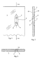
- a glass pane is designated 1. Within this Glass pane 1 is a fitting receptacle 2.
- the fitting fixture 2 consists of a recess 5, which, as shown in FIG Section has a shape of a circular section. In this section of the circle penetrate into it from a glass surface 22 of the glass pane 1, namely the opposite side of the glass surface 21 bores 3 and 4.
- the shape of the recess 5 is in the embodiment in Cross section shown as an ellipse.
- the shape of an ellipse lends itself because by a suitably trained cutter or a corresponding ground grinding wheel this shape by a simple Grinding processes are introduced into the surface 21 of the glass pane 1 can. If a grinding wheel is used, this results in FIG. 2 reproduced and exemplary in the following description shown execution as a circular section. This results in how it can be seen from FIG. 3 that the fitting receptacle in the top view 5 has the shape of a parabola.
- Such a fitting receptacle 2 is mechanically Manufacturing with tight tolerances so that in return the Fitting parts 6 and 13 to be used by an injection or casting process can be produced.
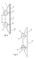
- the reproduced in Figures 4 and 5 Fitting parts 6 and 13 are the same in their outer contours.
- the Body of the fitting part that fills the recess 5 is one Circular arc 7 limited on the one hand and on the other hand by an outside 11th
- the exemplary embodiment in FIG. 5 shows in contrast to the exemplary embodiment 4 no through holes within the Approaches 8, 9, but threaded blind holes 12.
- This fitting part 13 is suitable if of the band parts to be used the fastening screws are to be inserted from the glass side 21.
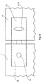
- Figure 6 shows such an assembly as previously described in the Front view, so for the viewer from the side from which the invention Fitting parts 6 and 13 are used, only the covers 18 are visible, and on the opposite side the band tabs 16, 17, which in this exemplary embodiment has an integrated circumferential seal 20 have. While in the embodiment of FIG. 6 in the left glass pane 1 two fittings are incorporated and only one fitting receptacle is incorporated into the right glass pane 15 8 in the band tabs of the glass panes 1 and 15, respectively only one fitting receptacle 2 incorporated. However, in this embodiment a flat seal 23 is shown.
- fitting parts 6, 13 has always been shown in a vertical version. Completeness half of it should be said that these are also horizontal in horizontal executed fittings recordings 2 can be performed.
Landscapes
- Engineering & Computer Science (AREA)
- Mechanical Engineering (AREA)
- Securing Of Glass Panes Or The Like (AREA)
Abstract
Description
- Figur 1:
- Einen Ausschnitt aus einer Glasscheibe mit einer eingearbeiteten Beschlagaufnahme in der Vorderansicht.
- Figur 2:
- Wie Figur 1, jedoch mit einer Schnittdarstellung in der Seitenansicht.
- Figur 3:
- Wie Figur 1, jedoch in der Draufsicht.
- Figur 4:
- Ein Beschlagteil mit einer Abdeckkappe.
- Figur 5:
- Eine zweite Ausführung eines Beschlagteiles.
- Figur 6:
- Eine Einbausituation in der Vorderansicht.
- Figur 7:
- Wie Figur 6 in der Draufsicht.
- Figur 8:
- Eine zweite Ausführung eines anzubringenden Beschlages.
- Figur 9:
- Eine Kombination von verschiedenen verwendeten Beschlagteilen.
- 1
- Glasscheibe
- 2
- Beschlagaufnahme
- 3
- Bohrung
- 4
- Bohrung
- 5
- Vertiefung
- 6
- Beschlagteil
- 7
- Kreisbogen
- 8
- Ansatz
- 9
- Ansatz
- 10
- Bohrung
- 11
- Außenseite
- 12
- Gewindebohrung
- 13
- Beschlagteil
- 14
- Vertiefung
- 15
- Glasscheibe
- 16
- Bandlappen
- 17
- Bandlappen
- 18
- Abdeckung
- 19
- Bandauge
- 20
- Dichtung
- 21
- Glasoberfläche
- 22
- Glasoberfläche
- 23
- Dichtung
- 24
- runde Vertiefung
- x
- Abstandsmaß
Claims (16)
- Befestigungsvorrichtung für feststehende und/oder bewegliche Glasscheiben (1, 15), dadurch gekennzeichnet, dass in den Glasscheiben (1, 15) eingearbeitete Beschlagaufnahmen (2) vorhanden sind, in denen Beschlagteile (6, 13) verdrehsicher eingelassen werden, die mit einer Glasoberfläche (21) bündig abschließen oder eine Außenseite (11) der Beschlagteile (6, 13) gegenüber der Glasoberfläche (21) zurückgesetzt ist und an einer gegenüberliegenden Glasoberfläche (22) mit einem Scharnier, Haltewinkel oder einem anderen Beschlagteil durch Schraubelemente kraft- und formschlüssig verbunden werden.
- Befestigungsvorrichtung nach Anspruch 1, dadurch gekennzeichnet, dass die Beschlagaufnahme (2) aus jeweils zwei die Glasscheiben (1, 15) durchdringende Bohrungen (3, 4) besteht, wobei zusätzlich eine von der Glasoberfläche (22) die beiden Bohrungen (3, 4) erfassende Vertiefung vorhanden ist, die in ihrer Tiefenerstreckung etwa die halbe Dicke der Glasscheiben (1, 15) erfasst.
- Befestigungsvorrichtung nach Anspruch 1 und 2, dadurch gekennzeichnet, dass die Vertiefung (5) rund in Form einer Sackbohrung ausgebildet ist.
- Befestigungsvorrichtung nach Anspruch 1 und 2, dadurch gekennzeichnet, dass die Vertiefung (5) in der Tiefe die Form eines Kreisabschnittes oder einer Ellipse und in der Breite und Höhe die Form einer Ellipse aufweist.
- Befestigungsvorrichtung nach Anspruch 1 und 2, dadurch gekennzeichnet, dass das Beschlagteil (6, 13) aus einem Stück besteht und eine komplementäre Form zu der Beschlagaufnahme (2) aufweist.
- Befestigungsvorrichtung nach Anspruch 1, dadurch gekennzeichnet, dass das Beschlagteil (13) eine Vertiefung (14) zur Aufnahme einer Abdeckscheibe (18) aufweist.
- Befestigungsvorrichtung nach Anspruch 1, dadurch gekennzeichnet, dass das Beschlagteil (6, 13) mit einer Abdeckscheibe (18) ganz oder teilweise abgedeckt wird.
- Befestigungsvorrichtung nach Anspruch 1, dadurch gekennzeichnet, dass das Beschlagteil (6) im Bereich seiner Ansätze (8, 9) Durchgangsbohrungen (10) aufweist, die an einer Außenseite (11) des Beschlages (6) Versenkungen zur Aufnahme von Schrauben aufweisen.
- Befestigungsvorrichtung nach Anspruch 6, dadurch gekennzeichnet, dass das Beschlagteil (13) im Bereich seiner Ansätze (8, 9) Gewindesackbohrungen (12) aufweist.
- Befestigungsvorrichtung nach einem oder mehreren der vorhergehende Ansprüche, dadurch gekennzeichnet, dass die Ansätze (8, 9) mit der Glasoberfläche (22) bündig abschließen.
- Befestigungsvorrichtung nach einem oder mehreren der vorhergehende Ansprüche, dadurch gekennzeichnet, dass die Ansätze (8, 9) aus der Glasoberfläche (22) herausragen und in Vertiefungen der anzuschlagenden Beschläge (16, 17), Haltewinkel oder Beschlagteile eingreifen.
- Befestigungsvorrichtung nach Anspruch 1, dadurch gekennzeichnet, dass die Scharniere, Haltewinkel oder anderen Beschlagteile an der zur Glasoberfläche (22) anliegenden Seite eine integrierte Dichtung aufweisen.
- Befestigungsvorrichtung nach einem oder mehreren der vorhergehende Ansprüche, dadurch gekennzeichnet, dass die Beschlagteile (6, 13) aus Kunststoff oder Metall oder Stahl bestehen.
- Befestigungsvorrichtung nach einem oder mehreren der vorhergehende Ansprüche, dadurch gekennzeichnet, dass die Glasscheibe (1, 15) bei Ganzglaswänden oder Duschabtrennungen eingesetzt wird.
- Verfahren zur Herstellung einer Beschlagaufnahme (2) nach den vorhergehenden Ansprüchen, dadurch gekennzeichnet, dass in einem ersten Arbeitsgang die Bohrungen (3, 4) als Sackbohrungen von der Glasoberfläche (22) der Glasscheibe (1) gebohrt werden und in einem zweiten Arbeitsgang anschließend die Vertiefung (5) durch ein geeignetes Schleif- und/oder Fräßverfahren von der gegenüberliegenden Glasoberfläche (21) eingearbeitet wird.
- Verfahren zur Montage eines Beschlagteiles (6, 13) gemäß den Ansprüchen 1 bis 13, dadurch gekennzeichnet, dass in die Beschlagaufnahme (2) ein aushärtbarer, transparenter Kleber dosiert eingebracht und anschließend das Beschlagteil (6, 13) eingesetzt wird.
Applications Claiming Priority (2)
| Application Number | Priority Date | Filing Date | Title |
|---|---|---|---|
| DE2000152125 DE10052125C2 (de) | 2000-10-19 | 2000-10-19 | Befestigungsvorrichtung für feststehende und/oder bewegliche Glasscheiben, sowie Verfahren zur Herstellung einer Beschlagaufnahme und Montage eines Beschlagteiles |
| DE10052125 | 2000-10-19 |
Publications (2)
| Publication Number | Publication Date |
|---|---|
| EP1199430A2 true EP1199430A2 (de) | 2002-04-24 |
| EP1199430A3 EP1199430A3 (de) | 2008-10-29 |
Family
ID=7660508
Family Applications (1)
| Application Number | Title | Priority Date | Filing Date |
|---|---|---|---|
| EP01124856A Withdrawn EP1199430A3 (de) | 2000-10-19 | 2001-10-18 | Befestigungsvorrichtung für feststehende und/oder bewegliche Glasscheiben, sowie Verfahren zur Herstellung einer Beschlagaufnahme und Montage eines Beschlagteiles |
Country Status (2)
| Country | Link |
|---|---|
| EP (1) | EP1199430A3 (de) |
| DE (1) | DE10052125C2 (de) |
Family Cites Families (4)
| Publication number | Priority date | Publication date | Assignee | Title |
|---|---|---|---|---|
| DE7705090U1 (de) * | 1977-02-19 | 1977-06-16 | Bfg Glassgroup, Paris | Klemmbeschlag fuer ganzglasanlagen |
| DE19945184A1 (de) * | 1999-09-21 | 2001-04-12 | Fischbach Joachim | Befestigungsvorrichtung für plattenförmige Bauteile |
| DE19949057C2 (de) * | 1999-10-12 | 2003-04-30 | Dorma Gmbh & Co Kg | Befestigungsvorrichtung für eine Duschabtrennung |
| DE10008858C2 (de) * | 2000-02-25 | 2003-04-30 | Dorma Gmbh & Co Kg | Befestigungsvorrichtung für feststehende und/oder bewegliche Glasscheiben |
-
2000
- 2000-10-19 DE DE2000152125 patent/DE10052125C2/de not_active Expired - Fee Related
-
2001
- 2001-10-18 EP EP01124856A patent/EP1199430A3/de not_active Withdrawn
Also Published As
| Publication number | Publication date |
|---|---|
| DE10052125C2 (de) | 2002-09-26 |
| DE10052125A1 (de) | 2002-05-16 |
| EP1199430A3 (de) | 2008-10-29 |
Similar Documents
| Publication | Publication Date | Title |
|---|---|---|
| EP1108843B1 (de) | Glaselement mit justierbarem Beschlag | |
| DE2748623A1 (de) | Beschlag fuer einen glasfluegel, insbesondere fuer eine ganzglastuer | |
| WO1999032746A1 (de) | Vorreiberverschluss für dickwandige türen, klappen oder dgl. | |
| DE19613156C1 (de) | Bausatz für einen Fensterflügelrahmen aus Holz | |
| DE2406706C3 (de) | Tür- bzw. Zargenteil für ein Türband | |
| EP2492424B1 (de) | Verbindungsvorrichtung einer Trennwand, insbesondere Duschtrennwand | |
| DE10052125C2 (de) | Befestigungsvorrichtung für feststehende und/oder bewegliche Glasscheiben, sowie Verfahren zur Herstellung einer Beschlagaufnahme und Montage eines Beschlagteiles | |
| EP0183985A1 (de) | Metallprofil für eine Türzarge und Türzarge hergestellt unter Verwendung eines derartigen Metallprofils | |
| DE2909229C2 (de) | Befestigungsanordnung eines Gelenkscharniers an einem am Korpus eines Möbelstücks vorgesehenen Rahmen | |
| WO2004085780A1 (de) | Band, insbesondere für dusch- und/oder glastüren | |
| EP1560996B1 (de) | Beschlaganordnung für glastüren | |
| EP0674076B1 (de) | Verfahren und Vorrichtung zum Anbringen der Befestigungsbohrungen für Rahmen- und Flügelbandteile | |
| DE19949057C2 (de) | Befestigungsvorrichtung für eine Duschabtrennung | |
| DE2514694A1 (de) | Blendrahmen mit abdeckprofil | |
| DE10009009A1 (de) | Beschlag für eine Duschabtrennung mit einer integrierten Dichtung | |
| DE4409155A1 (de) | Verbindungselement zur Verbindung von plattenförmigen Wandelementen | |
| EP0036480A1 (de) | Ganzglasflügel-Beschlag | |
| DE60130085T2 (de) | Kunststoffflügel, sowie sein Herstellungsverfahren und zweiflügelige Öffnung, z.B. für ein Fenster | |
| DE3516141C2 (de) | ||
| EP2518253A1 (de) | Eckverbindung für ein Flügelrahmenabdeckprofil | |
| DE19743489C1 (de) | Bausatz für einen Fensterflügelrahmen aus Holz | |
| DE102022003281B3 (de) | Türbandanordnung | |
| AT402530B (de) | Türflügel für gebäudeaussentür | |
| DE102004044906B4 (de) | Beschlag- und Befestigungssystem für Glaselemente | |
| AT412412B (de) | Adapterprofil |
Legal Events
| Date | Code | Title | Description |
|---|---|---|---|
| PUAI | Public reference made under article 153(3) epc to a published international application that has entered the european phase |
Free format text: ORIGINAL CODE: 0009012 |
|
| AK | Designated contracting states |
Kind code of ref document: A2 Designated state(s): AT BE CH CY DE DK ES FI FR GB GR IE IT LI LU MC NL PT SE TR |
|
| AX | Request for extension of the european patent |
Free format text: AL;LT;LV;MK;RO;SI |
|
| PUAL | Search report despatched |
Free format text: ORIGINAL CODE: 0009013 |
|
| AK | Designated contracting states |
Kind code of ref document: A3 Designated state(s): AT BE CH CY DE DK ES FI FR GB GR IE IT LI LU MC NL PT SE TR |
|
| AX | Request for extension of the european patent |
Extension state: AL LT LV MK RO SI |
|
| STAA | Information on the status of an ep patent application or granted ep patent |
Free format text: STATUS: THE APPLICATION HAS BEEN WITHDRAWN |
|
| 18W | Application withdrawn |
Effective date: 20081210 |