EP1199214A2 - Anti-submarine vehicle occupant restraint system - Google Patents
Anti-submarine vehicle occupant restraint system Download PDFInfo
- Publication number
- EP1199214A2 EP1199214A2 EP01308669A EP01308669A EP1199214A2 EP 1199214 A2 EP1199214 A2 EP 1199214A2 EP 01308669 A EP01308669 A EP 01308669A EP 01308669 A EP01308669 A EP 01308669A EP 1199214 A2 EP1199214 A2 EP 1199214A2
- Authority
- EP
- European Patent Office
- Prior art keywords
- vehicle occupant
- energy absorbing
- cross member
- seat
- pipe member
- Prior art date
- Legal status (The legal status is an assumption and is not a legal conclusion. Google has not performed a legal analysis and makes no representation as to the accuracy of the status listed.)
- Granted
Links
Images



Classifications
-
- B—PERFORMING OPERATIONS; TRANSPORTING
- B60—VEHICLES IN GENERAL
- B60N—SEATS SPECIALLY ADAPTED FOR VEHICLES; VEHICLE PASSENGER ACCOMMODATION NOT OTHERWISE PROVIDED FOR
- B60N2/00—Seats specially adapted for vehicles; Arrangement or mounting of seats in vehicles
- B60N2/24—Seats specially adapted for vehicles; Arrangement or mounting of seats in vehicles for particular purposes or particular vehicles
- B60N2/42—Seats specially adapted for vehicles; Arrangement or mounting of seats in vehicles for particular purposes or particular vehicles the seat constructed to protect the occupant from the effect of abnormal g-forces, e.g. crash or safety seats
- B60N2/427—Seats or parts thereof displaced during a crash
- B60N2/42727—Seats or parts thereof displaced during a crash involving substantially rigid displacement
- B60N2/42754—Seats or parts thereof displaced during a crash involving substantially rigid displacement of the cushion
- B60N2/42763—Seats or parts thereof displaced during a crash involving substantially rigid displacement of the cushion with anti-submarining systems
-
- B—PERFORMING OPERATIONS; TRANSPORTING
- B60—VEHICLES IN GENERAL
- B60N—SEATS SPECIALLY ADAPTED FOR VEHICLES; VEHICLE PASSENGER ACCOMMODATION NOT OTHERWISE PROVIDED FOR
- B60N2/00—Seats specially adapted for vehicles; Arrangement or mounting of seats in vehicles
- B60N2/24—Seats specially adapted for vehicles; Arrangement or mounting of seats in vehicles for particular purposes or particular vehicles
- B60N2/42—Seats specially adapted for vehicles; Arrangement or mounting of seats in vehicles for particular purposes or particular vehicles the seat constructed to protect the occupant from the effect of abnormal g-forces, e.g. crash or safety seats
- B60N2/4207—Seats specially adapted for vehicles; Arrangement or mounting of seats in vehicles for particular purposes or particular vehicles the seat constructed to protect the occupant from the effect of abnormal g-forces, e.g. crash or safety seats characterised by the direction of the g-forces
- B60N2/4214—Seats specially adapted for vehicles; Arrangement or mounting of seats in vehicles for particular purposes or particular vehicles the seat constructed to protect the occupant from the effect of abnormal g-forces, e.g. crash or safety seats characterised by the direction of the g-forces longitudinal
- B60N2/4221—Seats specially adapted for vehicles; Arrangement or mounting of seats in vehicles for particular purposes or particular vehicles the seat constructed to protect the occupant from the effect of abnormal g-forces, e.g. crash or safety seats characterised by the direction of the g-forces longitudinal due to impact coming from the front
-
- B—PERFORMING OPERATIONS; TRANSPORTING
- B60—VEHICLES IN GENERAL
- B60N—SEATS SPECIALLY ADAPTED FOR VEHICLES; VEHICLE PASSENGER ACCOMMODATION NOT OTHERWISE PROVIDED FOR
- B60N2/00—Seats specially adapted for vehicles; Arrangement or mounting of seats in vehicles
- B60N2/24—Seats specially adapted for vehicles; Arrangement or mounting of seats in vehicles for particular purposes or particular vehicles
- B60N2/42—Seats specially adapted for vehicles; Arrangement or mounting of seats in vehicles for particular purposes or particular vehicles the seat constructed to protect the occupant from the effect of abnormal g-forces, e.g. crash or safety seats
- B60N2/427—Seats or parts thereof displaced during a crash
- B60N2/42709—Seats or parts thereof displaced during a crash involving residual deformation or fracture of the structure
-
- B—PERFORMING OPERATIONS; TRANSPORTING
- B60—VEHICLES IN GENERAL
- B60N—SEATS SPECIALLY ADAPTED FOR VEHICLES; VEHICLE PASSENGER ACCOMMODATION NOT OTHERWISE PROVIDED FOR
- B60N2/00—Seats specially adapted for vehicles; Arrangement or mounting of seats in vehicles
- B60N2/24—Seats specially adapted for vehicles; Arrangement or mounting of seats in vehicles for particular purposes or particular vehicles
- B60N2/42—Seats specially adapted for vehicles; Arrangement or mounting of seats in vehicles for particular purposes or particular vehicles the seat constructed to protect the occupant from the effect of abnormal g-forces, e.g. crash or safety seats
- B60N2/427—Seats or parts thereof displaced during a crash
- B60N2/42772—Seats or parts thereof displaced during a crash characterised by the triggering system
- B60N2/4279—Seats or parts thereof displaced during a crash characterised by the triggering system electric or electronic triggering
Definitions
- the present invention relates to a vehicle occupant restraint system that is provided in a vehicle seat, and in particular to a vehicle occupant restraint system for preventing the submarining or slipping forward of the vehicle occupant under the seat belt in an impact situation such as a vehicle crash.
- submarining means the slipping forward of a vehicle occupant under the seat belt in an impact situation such as a vehicle crash in case the lap belt fails to restrain the pelvis of the vehicle occupant. This occurs most frequently when the vehicle occupant is sitting on an edge of the seat and/or the seat back is significantly reclined, and could impair the restraining capability of the seat belt because the seat belt fails to restrain the proper part of the vehicle occupant.
- a copending US patent application No. 09/526,405 filed March 15, 2000 discloses a vehicle occupant restraint system in which a forward slip preventing member is moveably supported by a pair of casings fixedly attached to either side of a seat frame at a front part of a seat bottom so as to selectively project upward.
- the front end of the seat is raised only in case of an impact situation such a vehicle crash by actuating this forward slip preventing member with a power unit.
- the front end of the seat or the cushion member of the seat cushion which is raised by the forward slip preventing member is almost entirely crushed by the load of the vehicle occupant in the impact situation, and the forward slip preventing member practically directly engages the legs of the vehicle occupant. This could cause some discomfort to the vehicle occupant, and a measure to reduce the impact is desired.
- a part or all of the cushion member may be formed with an energy absorbing material made of foamed resin or the like which provides a favorable energy absorbing property, but this not only increases the cost but also impairs the ride quality for the vehicle occupant as compared to the more conventional seat made solely of common cushion material.
- a primary object of the present invention is to provide an anti-submarine vehicle occupant restraint system which can reliably prevent the submarining in case of a vehicle crash.
- a second object of the present invention is to provide an anti-submarine vehicle occupant restraint system which can reduce the impact on the legs of the vehicle occupant when the forward slip preventing member is deployed.
- a third object of the present invention is to provide an anti-submarine vehicle occupant restraint system which is economical and easy to manufacture.
- a vehicle occupant restraint system provided in association with a vehicle seat for preventing a vehicle occupant from slipping forward under a seat belt in an impact situation such as a vehicle crash, comprising: a pair of fixed support members attached to either side of a seat frame at a front part of a seat bottom; an arm pivotally attached to a front end of each of the fixed support members; a cross member extending between free ends of the arms; and a power unit provided in association with at least one of the support members for actuating the arms and cross member upward so as to selectively raise a front part of the seat bottom in an impact situation such as a vehicle crash; the cross member comprising an energy absorbing structure adapted to undergo a controlled deformation under a load occurring as the front part of the seat bottom is raised.
- the energy absorbing structure allows the maximum load that is applied to the legs of the vehicle occupant to be controlled while restraining the vehicle occupant in an effective manner in case of a vehicle crash. By controlling the maximum load that is applied to the legs of the vehicle occupant, the injury to the vehicle occupant can be minimized.
- the energy absorbing structure may comprise a relatively deformable member placed over the cross member.
- a urethane foam sleeve having a controlled deformation property may be wrapped around the cross member.
- the cross member typically consists of a pipe member.
- the energy absorbing structure may comprise perforations formed in the pipe member or a relatively deformable member filled inside the pipe member.
- the pipe member may consist of a normal pipe having a circular cross section, or may be flattened in the part intended to engage the legs of the vehicle occupant.
- the pipe member may also be formed by stamp forming a single piece plate member or two piece plate members.
- the maximum load that is applied to the legs of the vehicle occupant can be controlled by adapting the cross member to undergo a deformation in a predictable manner. This can be achieved, for instance, by providing locally deformable parts such as slits, notches, holes, recesses and thin-walled parts in appropriate parts of the cross member or locally reinforced parts such as ribs and thick-walled parts.
- FIG. 1 is a perspective view of a vehicle seat 1 embodying the present invention.
- the vehicle seat 1 comprises a seat bottom 1a and a seat back 1b which is typically adapted to be reclined to a desired angle by an adjustable pivot mechanism not shown in the drawing.
- the seat bottom 1a comprises a seat frame 4 which in this case consists of a rectangular frame having a pair of longitudinal side members and a pair of cross members joining the front and rear ends of the side members with each other, and a cushion member 5 which covers the seat frame 4.
- the cushion member 5 may be simply made of foamed plastic material or consist of any known composite structure.
- a pair of subassemblies 2 and 3 forming a vehicle occupant restraint system according to the present invention are attached to the inner sides of the side members of the seat frame 4.
- the seat frame 4 may be supported by a seat rail assembly fixedly attached to the vehicle body via sliders in a slidable manner, and adapted to be fixed at a desired position with a seat adjust mechanism not shown in
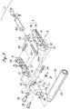
- FIGS 2 to 4 show the structure of the subassembly 2 on the right hand side of the vehicle occupant restraint system.
- the subassembly 2 comprises a tubular casing 6 having a rectangular cross section and elongated in the fore-and-aft direction of the vehicle body.
- the casing 6 is comprised of a main member 7 and a lid member 8 both of which are formed by stamp forming sheet metal.
- the main member 7 comprises a vertically extending section 7a and a pair of flanges 7b extending from upper and lower ends of the vertically extending section 7a toward the lid member 8.
- the upper and lower flanges 7a are smoothly connected to each other at the front end of the casing 6. Free ends of the upper and lower flanges 7b are provided with projecting tabs 9 which are fitted into corresponding openings 10 provided in the lid member 8, and crimped on the lid member 8.
- An arm 11 is pivotally attached to the front end of the casing 6.
- the arm 11 comprises a laterally extending web 11a and a pair of arm flanges 11b depending from either side of the web 11a.
- the upper front parts of the main member 7 and lid member 8 are provided with mutually aligned openings 12 and 13, and a corresponding opening 19 is passed through the arm flanges 11b.
- a collar 25 is passed through these openings 12, 13 and 19 to pivotally support the arm 11 with respect to the casing 6.
- a power unit comprising a cylinder unit 22 extending in a fore-and-aft direction and a piston rod 23 extending from a front end of the cylinder unit 22 is received in the casing 6.
- the front end of the piston rod 23 is provided with a ring 23a.
- the outer circumferential surface of the piston rod 23 is provided with annular or spiral grooves.
- the lower front parts of the main member 7 and lid member 8 are provided with slots 14 and 15 elongated in the fore-and-aft direction, and a corresponding oblique slot 18 which is only slightly elongated and offset from the opening 19 is passed through the arm flanges 11b.
- a pin 30 is passed through these slots 14, 18 and 15 and the ring 23a, and is retained therein by a retaining ring 31.
- the vertically extending section 7a of the main member 7 and lid member 8 are profiled so as to conform to or wrap around the cylindrical contour of the cylinder unit 22.
- Rectangular openings 16 and 17 are formed in intermediate parts of the main member 7 and lid member 8, and jointly retain therein a radial flange 22a formed in the front end of the cylinder unit 22 as well as a lock mechanism 24 provided on the front end of the radial flange 22a.
- the front facing edges of the rectangular openings 16 and 17 are adapted to support the reaction of the cylinder unit 22 at the time of its activation via the back surface of the radial flange 22a.
- edges are also contoured around the cylinder unit 22 as a result of the fact that the vertically extending section 7a of the main member 7 and lid member 8 are contoured around the cylinder unit 22, and are therefore allowed to abut the back surface of the radial flange 22a over a relatively large support surface.
- These rectangular openings 16 and 17 are each closed on all sides so that a high mechanical strength can be achieved with respect to the impact which is generated at the time of the activation of the vehicle occupant restraint system.
- This subassembly 2 is attached to the side member of the seat frame 4 by passing a pair of threaded bolts 26 and 29 through the collar 25 pivotally supporting the arm 11 and a hole 28 formed in a tab-like extension of the lid member 8 at an upper rear end thereof from inside the seat frame 4 and fastening nuts from the outside of the seat frame 4.
- the collar 25 is provided with an adequate length to support the axial force of the threaded bolt 26 without preventing the pivoting movement of the arm 11. Therefore, there is a play that permits a slight lateral movement of the arm 11 along the collar 25, and a rubber ring 27 interposed between a head of the collar 25 and a side of the arm 11 prevents any rattling of the arm 11 during use.
- FIGS. 5 and 6 show the structure of the subassembly 3 on the left hand side of the vehicle occupant restraint system.
- the subassembly 3 comprises a tubular casing 36 having a rectangular cross section and elongated in the fore-and-aft direction of the vehicle body.
- the casing 36 is comprised of a main member 37 and a lid member 38 both of which are formed by stamp forming sheet metal.
- the main member 37 comprises a vertically extending section 37a and a pair of flanges 37b extending from upper and lower ends of the vertically extending section 37a toward the lid member 38. Free ends of the upper and lower flanges 37b are provided with projecting tabs 39 which are fitted into corresponding openings 40 provided in the lid member 38, and crimped on the lid member 38.
- An arm 41 is pivotally attached to the front end of the casing 36.
- the arm 41 comprises a laterally extending web 41a and a pair of arm flanges 41b depending from either side of the web 41a.
- the upper front parts of the main member 37 and lid member 38 are provided with mutually aligned openings 42 and 43, and a corresponding opening 49 is passed through the arm flanges 41b.
- a collar 55 is passed through these openings 42, 43 and 49 to pivotally support the arm 41 with respect to the casing 36.
- a rod 53 extending in a fore-and-aft direction is received in the casing 36.
- the front end of the rod 53 is provided with a ring 53a.
- the outer circumferential surface of the rod 53 is provided with annular or spiral grooves.
- the lower front parts of the main member 37 and lid member 38 are provided with slots 44 and 45 elongated in the fore-and-aft direction, and a corresponding oblique slot 48 which is only slightly elongated and offset from the opening 49 is passed through the arm flanges 41b.
- a pin 60 is passed through these slots 44, 48 and 45 and the ring 53a, and is retained therein by a retaining ring 61.
- Rectangular openings 46 and 47 are formed in intermediate parts of the main member 37 and lid member 38, and jointly retain therein a lock mechanism 54 and the rod 53 is passed through this lock mechanism 54.
- This subassembly 3 is attached to the side member of the seat frame 4 by passing a pair of threaded bolts 56 and 59 through the collar 55 pivotally supporting the arm 41 and a hole 58 formed in a tab-like extension of the lid member 38 at an upper rear end thereof from inside the seat frame 4 and fastening nuts from the outside of the seat frame 4.
- the collar 55 is provided with an adequate length to support the axial force of the threaded bolt 56 without preventing the pivoting movement of the arm 41. Therefore, there is a play that permits a slight lateral movement of the arm along the collar, and a rubber ring 57 interposed between a head of the collar 55 and a side of the arm 41 prevents any rattling of the arm 41 during use.
- a cross member consisting of a pipe member 32 and serving as a forward slip preventing member extends across the free end 20 of the arm 11 of the subassembly 2 and the free end 50 of the arm 41 of the subassembly 3, and is welded to them.
- a cross member consisting of a pipe member 32 and serving as a forward slip preventing member extends across the free end 20 of the arm 11 of the subassembly 2 and the free end 50 of the arm 41 of the subassembly 3, and is welded to them.
- the free end 20 or 50 of each arm 11 or 41 consisting of the arm flanges are made narrower in width by bending the flanges 11b and 41b inwardly about vertical folding lines as indicated by numeral 21 and 51. This allows the pipe member 32 to extend outwardly beyond the outer profile of the free end 20 or 50 of the arm 11 or 41 without interfering with the seat frame 4 as shown in Figure 7. Because the pipe member 32 extends slightly beyond the outer profile of the free end of the arm, the welding work can be performed without the fear of melting away the terminal end of the pipe member 32.
- each end part 32a of the pipe member 32 is swaged or crimped radially inward. This allows an adequate amount of material to be provided for welding, and contributes to the prevention of the pipe member 32 from melting away at the time of welding.
- an energy absorbing member 70 is wrapped around the pipe member 32.
- This energy absorbing member 70 may be made of any material that can reduce the impact that is transmitted from the pipe member 32 to the vehicle occupant such as a tubular member made of foamed resin such as hard urethane. If a plurality of layers of different energy absorbing members 70 having different energy absorbing properties are used, a desired composite energy absorbing property may be achieved.
- the energy absorbing member 70 may be insert molded around the pipe member 32 or attached to the pipe member 32 afterwards.
- the cylinder unit 22 comprises a cylindrical cylinder member 72, a piston member 71 slidably received in the cylinder member 72 and a propellant module 73 received in an end of the cylinder member 72 remote from the flange 22a.
- the propellant module 73 is provided with a small diameter portion facing the piston member 71, and an annular seal member 74 is fitted on the small diameter portion so as to abut an annular shoulder defined at the base of the small diameter portion and the inner circumferential surface of the cylinder member 72 to seal off the gas that is produced from the small diameter portion when the propellant module 73 is activated.
- the end of the cylinder member 72 adjacent to the rear end of the propellant module 73 is crimped on the propellant module 73, and the annular seal 74 resiliently supports the propellant module 73 against the force of crimping.
- a compression coil spring 75 is interposed between the piston member 71 and the annular seal 74.
- the inner end of the piston rod 23 is provided with a spherical shape, and is received in a complementary spherical recess formed in the piston member 71.
- the lock mechanism 24 is provided with a casing 76 which internally defines a sloping surface 77.
- An engagement piece 78 is resiliently urged against this sloping surface 77 by a compression coil spring 79, and the slopping surface 77 is oriented in such a manner that the engagement piece 78 is resiliently urged also against the outer surface of the piston rod 23 under the spring force of the compression coil spring 79.
- the engagement piece 78 is provided with teeth 80 which mesh with the grooved surface of the piston rod 23.
- the engagement piece 78 would not prevent the outward movement of the piston rod 23 by being pushed away from the sloping surface 77 against the spring force of the compression coil spring 79, but prevents the inward movement of the piston rod 23 by wedging in between the sloping surface 77 and the outer circumferential surface of the piston rod 23.
- Only one engagement piece 78 was used in the above described embodiment to engage a part of the outer circumferential surface of the piston rod 23, but a plurality of engagement pieces may be used for engaging the outer circumferential surface of the piston rod 23 from a plurality of directions.
- the other lock mechanism 54 may be similar to the lock mechanism 24.
- the vehicle occupant restraint system is thus formed by the right and left subassemblies 2 and 3, and the pipe member 32.
- An impact detecting sensor consisting of an acceleration sensor or the like not shown in the drawing, and a control unit may be provided for activating the restraint system when appropriate.
- the annular shoulder formed in the inner circumferential surface of the cylinder member 72 at the flanged end of the cylinder unit 22 prevents the piston member 71 from being thrown forward out of the cylinder unit 22.
- the one-way lock mechanisms 24 and 54 prevent the pipe member 32 from coming down, and continues to prevent the submarining.
- the energy absorbing member 70 provides a required cushioning action.
- the cylinder unit 22 was provided only on the right hand side of the seat, but may also be provided on each side of the seat. If two cylinder units are used, each of them can be made smaller.
- the one-way lock mechanism may also consist of a ball type one-way lock mechanism which can prevent the reverse rotation in a continuous manner, a ratchet mechanism or the like.
- the energy absorbing member 70 was wrapped around the pipe member 32 serving as the forward slip preventing member as the energy absorbing structure in the illustrated embodiment, but the same goal can be achieved by giving a desired energy absorbing property to the pipe member by changing the material, wall thickness, diameter and cross sectional shape of the pipe member.
- Figures 10 and 11 show embodiments in which the forward slip preventing member comprises a pipe member 82 having a part thereof opposing the legs of the vehicle occupant flattened so as to define an engagement surface consisting of a flattened portion 82a for making a surface contact with the legs of the vehicle occupant and thereby reducing the surface pressure, as opposed to the normal pipe member 32, and an energy absorbing member 70 wrapped around the member 32.
- the embodiment illustrated in Figure 10 uses a pipe member 82 having the flattened portion 82a only in the central part thereof, and the embodiment illustrated in Figure 11 uses a pipe member 32 having the flattened portion 32a extending over the entire length thereof.
- Figures 12 to 14 show embodiment using a pipe member 83 serving as the forward slip preventing member formed with a plurality of holes 83a to control the deformation property thereof, instead of the normal pipe member 32.
- These holes 83a may be punched in a plate member which is then formed into a pipe.
- Figure 12 shows an embodiment in which the holes 83a consist of slots elongated in the axial direction
- Figure 13 shows an embodiment in which the holes 83a consist of circumferentially elongated slots
- Figure 14 shows an embodiment in which the holes 83a consist of a combination of axially elongated slots and circumferentially elongated slots.
- a desired deformation property can be achieved by suitably changing the size, number, shape and pitch of these holes 83a.
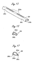
- Figures 15 and 16 show an embodiment in which a plate member is stamp formed into a pipe member 84 having a rectangular or elliptic cross section so as to present a flattened engagement surface 85 opposing the legs of the vehicle occupant and reduce the surface pressure by achieving a surface contact with the legs of the vehicle occupant.
- the two edges of the plate member may extend one next to the other in the manner of a depending flange 84b, and spot welded together to retain the tubular shape of the pipe member 84.
- This pipe member 84 is provided with a pair of ribs 84a extending in the axial direction on either side of the center of the pipe member 84, and a pair of notches 84c are provided in the depending flange 84b adjacent to the terminal ends thereof.
- the ribs 84a locally increase the resistance to the bending deformation of the pipe member 84 while the notches 84c locally decrease the resistance to the bending deformation. Therefore, this pipe member 84 is adapted to undergo a controlled and predicable bending deformation when subjected to a loading at the time of its deployment.
- Figure 17 is a modified embodiment of the pipe member 86 which is made of a pair of plate members 86a and 86b which are joined at a pair of depending flanges 86c.
- the pipe member 86 is provided with an elliptic cross section and the two plate members 86a and 86b are joined along the flanges 86c by spot welding.
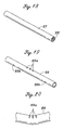
- Figure 18 shows an embodiment of the forward slip preventing member made of a pipe member 87 having a relatively thin wall, as opposed to the normal pipe member 32, which is filled with an energy absorbing material 88.
- the energy absorbing member 88 may be inserted in the pipe member 87 or foamed inside the pipe member 87.
- a structural member made of a thin plate member and having a closed cross section typically collapses locally, and is therefore unable to provide a desired load property. However, when it is filled with an energy absorbing member 88, it can be avoided, and a desired energy absorbing property as well as a desired deformation property can be achieved.
- the deformation property is controlled by forming a plurality of circumferential slits 89a in the pipe member 89 on the side facing the legs of the vehicle occupant, instead of a normal pipe member 32.
- a pair of recesses 89b are formed on the underside of the pipe member 89 adjacent to either terminal end thereof.
- the energy absorbing structure was used either by itself or in combination with the engagement surface arrangement adapted to make a surface contact with the legs of the vehicle occupant, but it is also possible to use the engagement surface arrangement adapted to make a surface contact with the legs of the vehicle occupant by itself, or in combination with any other arrangements.
Landscapes
- Engineering & Computer Science (AREA)
- Aviation & Aerospace Engineering (AREA)
- Transportation (AREA)
- Mechanical Engineering (AREA)
- Seats For Vehicles (AREA)
- Vibration Dampers (AREA)
Abstract
Description
Claims (5)
- A vehicle occupant restraint system provided in association with a vehicle seat for preventing a vehicle occupant from slipping forward under a seat belt in an impact situation such as a vehicle crash, comprising:a pair of fixed support members attached to either side of a seat frame at a front part of a seat bottom;an arm pivotally attached to a front end of each of said fixed support members;a cross member extending between free ends of said arms; anda power unit provided in association with at least one of said support members for actuating said arms and cross member upward so as to selectively raise a front part of said seat bottom in an impact situation such as a vehicle crash;said cross member comprising an energy absorbing structure adapted to undergo a controlled deformation under a load occurring as said front part of said seat bottom is raised.
- A vehicle occupant restraint system according to claim 1, wherein said energy absorbing structure comprises a relatively deformable member placed over said cross member.
- A vehicle occupant restraint system according to claim 1, wherein said cross member comprises a pipe member, and said energy absorbing structure comprises perforations formed in said pipe member.
- A vehicle occupant restraint system according to claim 1, wherein said cross member comprises a pipe member, and said energy absorbing structure comprises a relatively deformable member filled inside said pipe member.
- A vehicle occupant restraint system according to claim 1, wherein said energy absorbing structure comprises a feature for controlling a mode of deformation of said cross member.
Applications Claiming Priority (2)
| Application Number | Priority Date | Filing Date | Title |
|---|---|---|---|
| JP2000314327 | 2000-10-13 | ||
| JP2000314327 | 2000-10-13 |
Publications (3)
| Publication Number | Publication Date |
|---|---|
| EP1199214A2 true EP1199214A2 (en) | 2002-04-24 |
| EP1199214A3 EP1199214A3 (en) | 2003-12-17 |
| EP1199214B1 EP1199214B1 (en) | 2006-06-21 |
Family
ID=18793608
Family Applications (1)
| Application Number | Title | Priority Date | Filing Date |
|---|---|---|---|
| EP01308669A Expired - Lifetime EP1199214B1 (en) | 2000-10-13 | 2001-10-11 | Anti-submarining vehicle occupant restraint system |
Country Status (3)
| Country | Link |
|---|---|
| US (1) | US6837540B2 (en) |
| EP (1) | EP1199214B1 (en) |
| DE (1) | DE60120871T2 (en) |
Cited By (13)
| Publication number | Priority date | Publication date | Assignee | Title |
|---|---|---|---|---|
| DE20301516U1 (en) | 2003-01-31 | 2003-07-10 | TRW Occupant Restraint Systems GmbH & Co. KG, 73553 Alfdorf | vehicle seat |
| DE20211553U1 (en) * | 2002-07-12 | 2003-11-20 | Johnson Controls GmbH, 51399 Burscheid | Seat part for a vehicle seat |
| DE10231794A1 (en) * | 2002-07-10 | 2004-02-12 | Takata-Petri Ag | Automotive seat |
| WO2005047054A1 (en) * | 2003-11-07 | 2005-05-26 | Johnson Controls Gmbh | Vehicle seat comprising an adjustable safety means for preventing especially an accident-related excessive forward displacement of the pelvis |
| DE102004015467A1 (en) * | 2004-03-26 | 2005-10-20 | Heraeus Gmbh W C | Electrode system with a current feed through a ceramic component |
| WO2007147636A1 (en) | 2006-06-23 | 2007-12-27 | Johnson Controls Gmbh | Vehicle seat comprising a seat part and an anti-submarining restraint device, restraint device and method of manufacture |
| EP2042368A3 (en) * | 2007-09-27 | 2009-11-04 | Aisin Seiki Kabushiki Kaisha | Positioning apparatus of seat for vehicle |
| US8297697B2 (en) | 2006-06-23 | 2012-10-30 | Johnson Controls Gmbh | Vehicle seat having an anti-submarining device and method |
| WO2012140019A3 (en) * | 2011-04-15 | 2013-01-31 | C. Rob. Hammerstein Gmbh & Co. Kg | Seat body for a motor vehicle seat |
| US8393681B2 (en) | 2006-06-23 | 2013-03-12 | Johnson Controls Gmbh | Vehicle seat having an anti-submarining device and method |
| CN103241156A (en) * | 2012-02-01 | 2013-08-14 | 丰田纺织株式会社 | Seat cushion frame for vehicle |
| FR2987322A1 (en) * | 2012-02-28 | 2013-08-30 | Peugeot Citroen Automobiles Sa | Padded seat for vehicle i.e. car, has cross-piece comprising section having flat surface, where flat surface is directed to receive efforts generated by base of user during displacement |
| DE102013201406B4 (en) | 2012-02-01 | 2025-10-23 | Toyota Boshoku Kabushiki Kaisha | Vehicle seat cushion frame |
Families Citing this family (30)
| Publication number | Priority date | Publication date | Assignee | Title |
|---|---|---|---|---|
| US6758520B2 (en) * | 2001-01-05 | 2004-07-06 | Ford Global Technologies, Inc. | Adjustable height automotive seat |
| EP1362737A4 (en) * | 2001-02-21 | 2008-12-31 | Daihatsu Motor Co Ltd | CAR SEAT |
| US6773075B2 (en) * | 2002-01-24 | 2004-08-10 | Ford Global Technologies, Llc | Four point seat belt restraint system |
| US7514107B2 (en) * | 2002-03-21 | 2009-04-07 | Mars, Incorporated | Treatment of diseases involving defective gap junctional communication |
| JP4004342B2 (en) * | 2002-07-02 | 2007-11-07 | 日本発条株式会社 | Crew restraint system |
| DE10340996B3 (en) * | 2003-09-05 | 2005-03-10 | Keiper Gmbh & Co Kg | Vehicle seat with anti-submarine ramp |
| US7063383B2 (en) * | 2004-10-18 | 2006-06-20 | Shang Neng Wu | Sliding assembly of dynamic mechanism of a massage chair |
| JP4496924B2 (en) * | 2004-11-04 | 2010-07-07 | アイシン精機株式会社 | Vehicle seat device |
| GB2421277B (en) * | 2004-12-20 | 2009-10-14 | Autoliv Dev | Improvements in or relating to a seat back support mechanism |
| EP1944191B1 (en) * | 2005-01-19 | 2013-04-10 | Takata AG | Steering wheel assembly for a motor vehicle |
| WO2006076898A2 (en) * | 2005-01-19 | 2006-07-27 | Takata-Petri Ag | Safety device for an automotive seat and method for controlling the same |
| DE102007049864B4 (en) * | 2007-01-31 | 2017-08-03 | Adient Luxembourg Holding S.à.r.l. | Seat frame of a motor vehicle seat with a seat support, which has two side parts |
| CA2623119A1 (en) * | 2007-03-02 | 2008-09-02 | M2K, Llc. | Seat assembly for a vehicle |
| CA2677454A1 (en) * | 2008-08-29 | 2010-02-28 | Syntec Seating Solutions, Llc. | Seat assembly for a vehicle |
| US8123293B2 (en) * | 2008-12-15 | 2012-02-28 | Syntec Seating Solutions Llc | Seat assembly with rotatable seat bottom |
| CN103448584B (en) * | 2013-09-11 | 2016-06-15 | 清华大学苏州汽车研究院(相城) | A kind of for adaptive intelligent translational energy-absorbing seat under rear-end impact |
| US9403452B2 (en) | 2014-07-17 | 2016-08-02 | Fca Us Llc | Vehicle seat bottom assembly having an anti-submarine device |
| JP6561664B2 (en) * | 2015-08-03 | 2019-08-21 | テイ・エス テック株式会社 | Vehicle seat |
| FR3039793B1 (en) * | 2015-08-05 | 2017-09-15 | Expliseat | DEFORMABLE SEAT FOR VEHICLE |
| SE541442C2 (en) * | 2015-09-07 | 2019-10-01 | Ningbo Geely Automobile Res & Development Co Ltd | Method and vehicle seat arrangement comprising a deformation portion |
| US10227022B2 (en) * | 2016-09-20 | 2019-03-12 | Toyota Boshoku Kabushiki Kaisha | Tilt arm for seat and vehicle seat |
| US10173558B1 (en) | 2017-08-25 | 2019-01-08 | Ford Global Technologies, Llc | Vehicle seat assembly with deployable airbag |
| JP6962845B2 (en) * | 2018-03-29 | 2021-11-05 | 日本発條株式会社 | Vehicle seat |
| JP7040407B2 (en) * | 2018-11-05 | 2022-03-23 | トヨタ自動車株式会社 | Vehicle seat |
| US10821863B1 (en) * | 2019-06-24 | 2020-11-03 | Ford Global Technologies, Llc | Retention member for vehicle seating assembly |
| US11072265B2 (en) * | 2019-09-18 | 2021-07-27 | Lear Corporation | Vehicle seat assembly with front seat pan height adjustment mechanism |
| KR20220014920A (en) * | 2020-07-29 | 2022-02-08 | 현대자동차주식회사 | Seat support assembly for automobile |
| KR102275536B1 (en) * | 2021-02-16 | 2021-07-09 | 주식회사 듀오백 | Leg supporter structure for seat plate of chair |
| FR3123322B1 (en) | 2021-05-28 | 2024-06-28 | Safran Seats | SEAT SEAT, IN PARTICULAR AN AIRCRAFT SEAT, PROVIDED WITH A KINETIC ENERGY ABSORBING TUBE |
| US12545157B2 (en) * | 2023-11-17 | 2026-02-10 | Ford Global Technologies, Llc | Lifter for vehicle seat bottom |
Family Cites Families (68)
| Publication number | Priority date | Publication date | Assignee | Title |
|---|---|---|---|---|
| US2970862A (en) * | 1959-04-22 | 1961-02-07 | Protect O Matic Corp | Safety vehicle seat mechanism |
| US3591232A (en) | 1969-04-01 | 1971-07-06 | Lewis B Simon | Automatic vehicle occupant restraint |
| GB1348873A (en) * | 1972-02-11 | 1974-03-27 | Ford Motor Co | Motor vehicle seat |
| US3858930A (en) | 1972-07-11 | 1975-01-07 | Donald A Calandra | Safety vehicle seat system and trigger means for the same |
| FR2239870A1 (en) | 1973-08-03 | 1975-02-28 | Poudres & Explosifs Ste Nale | |
| DE2349829C2 (en) | 1973-10-04 | 1982-12-30 | Daimler-Benz Ag, 7000 Stuttgart | Restraint device for the occupants of vehicles |
| DE2802617C2 (en) | 1978-01-21 | 1985-01-10 | Keiper Automobiltechnik Gmbh & Co Kg, 5630 Remscheid | Anchoring for seat belt buckles |
| JPS5835U (en) | 1981-06-26 | 1983-01-05 | トヨタ自動車株式会社 | Seat front height adjustment device |
| JPS5853525A (en) | 1981-09-25 | 1983-03-30 | Mazda Motor Corp | Seat for automobile |
| JPS6036797U (en) | 1983-08-19 | 1985-03-13 | 株式会社タチエス | Vehicle seat with thigh support device |
| US4589696A (en) | 1984-07-12 | 1986-05-20 | Tachikawa Spring Co., Ltd. | Adjustment/engagement device in a vehicle seat |
| US4705296A (en) | 1985-02-21 | 1987-11-10 | Autoliv Development Ab | Seat belt pre-tensioning device |
| JPS61158538U (en) * | 1985-03-26 | 1986-10-01 | ||
| DE3729505A1 (en) | 1987-09-03 | 1989-03-23 | Bsrd Ltd | DEVICE FOR TIGHTENING A SEAT BELT OF A VEHICLE, IN PARTICULAR MOTOR VEHICLE |
| US5022707A (en) * | 1988-01-07 | 1991-06-11 | Life Force Associates, L.P. | Vehicle safety device |
| JPH01275230A (en) | 1988-04-27 | 1989-11-02 | Honda Motor Co Ltd | Vehicle seat |
| JPH0610230Y2 (en) | 1988-11-17 | 1994-03-16 | エヌティエヌ株式会社 | Rotating body with one-way clutch |
| JPH02149328A (en) | 1988-11-29 | 1990-06-07 | Matsushita Electric Ind Co Ltd | Mixing device |
| DE3841688A1 (en) | 1988-12-10 | 1990-06-21 | Daimler Benz Ag | VEHICLE SEAT WITH A U-SHAPED BRACKET ASSIGNED TO THE SEAT CUSHION |
| NL8900892A (en) | 1989-04-10 | 1990-11-01 | Werner & Pfleiderer Haton Bv | DOUGH ROLLING DEVICE. |
| US5152552A (en) | 1989-09-28 | 1992-10-06 | Fuji Kiko Company, Ltd. | Emergency tensioning device for automotive seat belt |
| JPH03121947A (en) | 1989-10-04 | 1991-05-23 | Seiyoo Denshi Kk | Accident site recording device |
| JPH03227745A (en) | 1989-12-25 | 1991-10-08 | Mazda Motor Corp | Crew position control device |
| ES2026834T3 (en) | 1990-05-11 | 1994-01-01 | Trw Repa Gmbh | ACTIVATION MECHANISM FOR RETRACTION FACILITIES IN VEHICLES. |
| JP2567133B2 (en) | 1990-07-11 | 1996-12-25 | 日産自動車株式会社 | Car occupant restraint system |
| JPH0493222A (en) | 1990-08-08 | 1992-03-26 | Yazaki Corp | Removing method and device for metallic foreign matter mixed into pelletlike insulation material |
| DE4032385C2 (en) | 1990-10-12 | 1994-06-23 | Audi Ag | Safety device for a vehicle occupant |
| US5288105A (en) | 1991-02-27 | 1994-02-22 | Fuji Kiko Co., Ltd. | Safety belt system with emergency retraction capability |
| DE59104340D1 (en) | 1991-08-16 | 1995-03-02 | Trw Repa Gmbh | Release mechanism for belt tensioners. |
| JPH05229378A (en) | 1992-02-20 | 1993-09-07 | Toyota Motor Corp | Vehicle seat |
| DE4222985A1 (en) | 1992-05-05 | 1993-11-11 | Trw Repa Gmbh | Linear drive for a belt tensioner |
| FR2693157B1 (en) | 1992-07-03 | 1994-09-09 | Faure Bertrand Automobile | Improvements to devices for locking adjustable components in position of vehicle seats during impacts. |
| US5282672A (en) | 1992-07-20 | 1994-02-01 | General Motors Corporation | Vehicular seat with occupant restraint system |
| US5374105A (en) | 1992-11-19 | 1994-12-20 | Hoover Universal, Inc. | Vehicle seat assembly with improved front panel |
| JPH0781466A (en) | 1993-09-10 | 1995-03-28 | Nissan Motor Co Ltd | Seat lower structure for restraining forward movement of passengers |
| US5449214A (en) | 1993-10-27 | 1995-09-12 | Totani; Hideo | Safety system for an occupant of an automotive vehicle |
| US5485970A (en) | 1994-03-21 | 1996-01-23 | Trw Vehicle Safety Systems Inc. | Seat belt pretensioner |
| US5451094A (en) | 1994-06-27 | 1995-09-19 | Indiana Mills & Manufacturing, Inc. | Seat and occupant restraint system |
| DE4423957A1 (en) | 1994-07-07 | 1996-01-11 | Keiper Recaro Gmbh Co | Vehicle seat with carrier and support strut |
| US5556160A (en) | 1994-10-04 | 1996-09-17 | Mikami; Tatuya | Seat with user protecting means |
| US5490706A (en) | 1995-03-22 | 1996-02-13 | Totani; Hideo | Safety system for occupant of an automotive vehicle |
| US5647628A (en) | 1995-05-10 | 1997-07-15 | Epilogics, Inc. | Linear one way movement device and passenger seat assembly using the device |
| FR2734766B1 (en) | 1995-05-30 | 1997-07-25 | Faure Bertrand Equipements Sa | AUTOMOBILE SEAT WITH ADJUSTABLE SEAT SURFACE |
| JPH0914301A (en) | 1995-06-27 | 1997-01-14 | Ntn Corp | One-way clutch |
| GB9516540D0 (en) | 1995-08-11 | 1995-10-11 | Alliedsignal Ltd | Pretensioner |
| US5695242A (en) | 1996-02-15 | 1997-12-09 | Breed Automotive Technology, Inc. | Seat cushion restraint system |
| DE29610078U1 (en) | 1996-06-07 | 1996-10-02 | Trw Occupant Restraint Systems Gmbh, 73551 Alfdorf | Restraint system for vehicle occupants |
| DE19707998B4 (en) | 1997-02-27 | 2007-04-05 | Inova Gmbh Technische Entwicklungen | Automotive seat |
| FR2754498B1 (en) * | 1996-10-11 | 1998-11-27 | Renault | MOTOR VEHICLE SEAT WITH ENERGY ABSORPTION ANTI-SOUMARINAGE DEVICE |
| JP3780371B2 (en) | 1996-12-25 | 2006-05-31 | 株式会社ジェイテクト | One-way clutch |
| JPH10181529A (en) | 1996-12-27 | 1998-07-07 | Nhk Spring Co Ltd | Nonreturn device and seat belt pretensioner device |
| JPH10181527A (en) | 1996-12-27 | 1998-07-07 | Nhk Spring Co Ltd | Pretensioner device for seat belt |
| GB2320886B (en) | 1996-12-27 | 2001-04-11 | Nhk Spring Co Ltd | Seat belt pre-tensioner assembly |
| GB2330334A (en) | 1997-06-02 | 1999-04-21 | Alliedsignal Ltd | Buckle pretensioner for a vehicle |
| FR2771688B1 (en) * | 1997-11-28 | 2000-01-28 | Faure Bertrand Equipements Sa | SEAT HAVING AN INTEGRATED SAFETY BELT |
| FR2772690B1 (en) | 1997-12-24 | 2000-02-18 | Faure Bertrand Equipements Sa | SEAT OF A MOTOR VEHICLE SEAT COMPRISING AN ANTI-SUBMARINE CROSSING |
| JP3662739B2 (en) | 1998-04-20 | 2005-06-22 | 本田技研工業株式会社 | Seat belt pretensioner |
| WO1999058377A1 (en) | 1998-05-08 | 1999-11-18 | Breed Automotive Technology, Inc. | Pretensioner |
| JP3715106B2 (en) * | 1998-06-16 | 2005-11-09 | 日本発条株式会社 | Vehicle seat device |
| JP4080609B2 (en) | 1998-09-29 | 2008-04-23 | 日本発条株式会社 | Vehicle seat |
| FR2789026B1 (en) * | 1999-01-28 | 2001-04-06 | Faure Bertrand Equipements Sa | VEHICLE SEAT HAVING A MOBILE SAFETY CROSSING |
| JP2000264114A (en) | 1999-03-15 | 2000-09-26 | Nhk Spring Co Ltd | Vehicle seat device |
| DE10011817B4 (en) * | 1999-03-15 | 2005-05-25 | NHK Spring Co., Ltd., Yokohama | Vehicle seat device for lifting a front seat part |
| JP3730434B2 (en) | 1999-03-26 | 2006-01-05 | 日本発条株式会社 | Submarine prevention device for vehicles |
| DE19942975C1 (en) * | 1999-09-09 | 2000-11-23 | Keiper Gmbh & Co | Vehicle seat has a pitch adjustment through a setting unit with a shaft at the leading section fitted to the frame side sections with free play for movement in the event of a collision |
| US6361109B1 (en) * | 1999-09-27 | 2002-03-26 | Magna Seating Systems Inc. | Seat cushion height adjuster |
| JP4595192B2 (en) * | 1999-11-30 | 2010-12-08 | アイシン精機株式会社 | Seat vertical device |
| JP3745181B2 (en) | 1999-12-22 | 2006-02-15 | 日本発条株式会社 | Crew restraint system |
-
2001
- 2001-10-11 EP EP01308669A patent/EP1199214B1/en not_active Expired - Lifetime
- 2001-10-11 DE DE60120871T patent/DE60120871T2/en not_active Expired - Lifetime
- 2001-10-12 US US09/976,324 patent/US6837540B2/en not_active Expired - Lifetime
Cited By (18)
| Publication number | Priority date | Publication date | Assignee | Title |
|---|---|---|---|---|
| US7413246B2 (en) | 2002-07-10 | 2008-08-19 | Takata Corporation | Safety device for motor vehicle |
| DE10231794A1 (en) * | 2002-07-10 | 2004-02-12 | Takata-Petri Ag | Automotive seat |
| DE20211553U1 (en) * | 2002-07-12 | 2003-11-20 | Johnson Controls GmbH, 51399 Burscheid | Seat part for a vehicle seat |
| WO2004007239A1 (en) * | 2002-07-12 | 2004-01-22 | Johnson Controls Gmbh | Seat component for a vehicle seat |
| DE20301516U1 (en) | 2003-01-31 | 2003-07-10 | TRW Occupant Restraint Systems GmbH & Co. KG, 73553 Alfdorf | vehicle seat |
| WO2005047054A1 (en) * | 2003-11-07 | 2005-05-26 | Johnson Controls Gmbh | Vehicle seat comprising an adjustable safety means for preventing especially an accident-related excessive forward displacement of the pelvis |
| DE102004015467B4 (en) * | 2004-03-26 | 2007-12-27 | W.C. Heraeus Gmbh | Electrode system with a current feed through a ceramic component |
| DE102004015467A1 (en) * | 2004-03-26 | 2005-10-20 | Heraeus Gmbh W C | Electrode system with a current feed through a ceramic component |
| WO2007147636A1 (en) | 2006-06-23 | 2007-12-27 | Johnson Controls Gmbh | Vehicle seat comprising a seat part and an anti-submarining restraint device, restraint device and method of manufacture |
| US8272687B2 (en) | 2006-06-23 | 2012-09-25 | Johnson Controls Gmbh | Vehicle seat having an anti-submarining device and method |
| US8297697B2 (en) | 2006-06-23 | 2012-10-30 | Johnson Controls Gmbh | Vehicle seat having an anti-submarining device and method |
| US8393681B2 (en) | 2006-06-23 | 2013-03-12 | Johnson Controls Gmbh | Vehicle seat having an anti-submarining device and method |
| EP2042368A3 (en) * | 2007-09-27 | 2009-11-04 | Aisin Seiki Kabushiki Kaisha | Positioning apparatus of seat for vehicle |
| WO2012140019A3 (en) * | 2011-04-15 | 2013-01-31 | C. Rob. Hammerstein Gmbh & Co. Kg | Seat body for a motor vehicle seat |
| CN103241156A (en) * | 2012-02-01 | 2013-08-14 | 丰田纺织株式会社 | Seat cushion frame for vehicle |
| CN103241156B (en) * | 2012-02-01 | 2016-03-16 | 丰田纺织株式会社 | For the cushion frame of vehicle |
| DE102013201406B4 (en) | 2012-02-01 | 2025-10-23 | Toyota Boshoku Kabushiki Kaisha | Vehicle seat cushion frame |
| FR2987322A1 (en) * | 2012-02-28 | 2013-08-30 | Peugeot Citroen Automobiles Sa | Padded seat for vehicle i.e. car, has cross-piece comprising section having flat surface, where flat surface is directed to receive efforts generated by base of user during displacement |
Also Published As
| Publication number | Publication date |
|---|---|
| DE60120871D1 (en) | 2006-08-03 |
| EP1199214B1 (en) | 2006-06-21 |
| DE60120871T2 (en) | 2007-01-18 |
| EP1199214A3 (en) | 2003-12-17 |
| US6837540B2 (en) | 2005-01-04 |
| US20020053792A1 (en) | 2002-05-09 |
Similar Documents
| Publication | Publication Date | Title |
|---|---|---|
| EP1199214B1 (en) | Anti-submarining vehicle occupant restraint system | |
| US6450573B1 (en) | Anti-submarine vehicle seat device | |
| EP1197381B1 (en) | Anti-submarine vehicle occupant restraint system | |
| US7104601B2 (en) | Vehicle occupant restraint system | |
| EP1371518B1 (en) | Occupant protecting device | |
| JP5172831B2 (en) | Vehicle seat provided with seat portion and anti-submarine restraint device, restraint device and manufacturing method | |
| JP5286256B2 (en) | Vehicle seat provided with seat portion and anti-submarine restraint device, restraint device and manufacturing method | |
| US6604599B2 (en) | Anti-submarine vehicle occupant restraint system | |
| US6817672B2 (en) | Seatback frame for vehicle seat | |
| US6474734B1 (en) | Emergency locking seat hinge device and vehicle seat using the same | |
| JP3959635B2 (en) | Automotive seat | |
| JP6584692B2 (en) | Seat belt pretension retractor assembly | |
| US6113185A (en) | Vehicle seat | |
| GB2347902A (en) | Power actutor for use in vehicle safety systems | |
| JP2001239872A (en) | Occupant crash protection device | |
| CN115461253A (en) | Retractor pretensioner assembly | |
| JP4165217B2 (en) | Crew protection device | |
| US20050104341A1 (en) | Occupant protecting device | |
| JP5156576B2 (en) | Rear impact shock absorbing unit, reclining device, and vehicle seat frame structure | |
| JP2011020659A (en) | Vehicle seat | |
| JP3730434B2 (en) | Submarine prevention device for vehicles | |
| JP2010052622A (en) | Occupant crash protector | |
| JP4005237B2 (en) | Vehicle seat | |
| JP5156422B2 (en) | Rear impact shock absorbing unit and vehicle seat | |
| EP1765644B1 (en) | An air-bag |
Legal Events
| Date | Code | Title | Description |
|---|---|---|---|
| PUAI | Public reference made under article 153(3) epc to a published international application that has entered the european phase |
Free format text: ORIGINAL CODE: 0009012 |
|
| AK | Designated contracting states |
Kind code of ref document: A2 Designated state(s): AT BE CH CY DE DK ES FI FR GB GR IE IT LI LU MC NL PT SE TR |
|
| AX | Request for extension of the european patent |
Free format text: AL;LT;LV;MK;RO;SI |
|
| PUAL | Search report despatched |
Free format text: ORIGINAL CODE: 0009013 |
|
| RIC1 | Information provided on ipc code assigned before grant |
Ipc: 7B 60N 2/42 A Ipc: 7B 60N 2/427 B |
|
| AK | Designated contracting states |
Kind code of ref document: A3 Designated state(s): AT BE CH CY DE DK ES FI FR GB GR IE IT LI LU MC NL PT SE TR |
|
| AX | Request for extension of the european patent |
Extension state: AL LT LV MK RO SI |
|
| 17P | Request for examination filed |
Effective date: 20040318 |
|
| AKX | Designation fees paid |
Designated state(s): DE FR GB |
|
| 17Q | First examination report despatched |
Effective date: 20050310 |
|
| GRAJ | Information related to disapproval of communication of intention to grant by the applicant or resumption of examination proceedings by the epo deleted |
Free format text: ORIGINAL CODE: EPIDOSDIGR1 |
|
| GRAP | Despatch of communication of intention to grant a patent |
Free format text: ORIGINAL CODE: EPIDOSNIGR1 |
|
| GRAP | Despatch of communication of intention to grant a patent |
Free format text: ORIGINAL CODE: EPIDOSNIGR1 |
|
| RTI1 | Title (correction) |
Free format text: ANTI-SUBMARINING VEHICLE OCCUPANT RESTRAINT SYSTEM |
|
| GRAS | Grant fee paid |
Free format text: ORIGINAL CODE: EPIDOSNIGR3 |
|
| GRAA | (expected) grant |
Free format text: ORIGINAL CODE: 0009210 |
|
| AK | Designated contracting states |
Kind code of ref document: B1 Designated state(s): DE FR GB |
|
| REG | Reference to a national code |
Ref country code: GB Ref legal event code: FG4D |
|
| REF | Corresponds to: |
Ref document number: 60120871 Country of ref document: DE Date of ref document: 20060803 Kind code of ref document: P |
|
| ET | Fr: translation filed | ||
| PLBE | No opposition filed within time limit |
Free format text: ORIGINAL CODE: 0009261 |
|
| STAA | Information on the status of an ep patent application or granted ep patent |
Free format text: STATUS: NO OPPOSITION FILED WITHIN TIME LIMIT |
|
| 26N | No opposition filed |
Effective date: 20070322 |
|
| PGFP | Annual fee paid to national office [announced via postgrant information from national office to epo] |
Ref country code: GB Payment date: 20131009 Year of fee payment: 13 Ref country code: FR Payment date: 20131009 Year of fee payment: 13 Ref country code: DE Payment date: 20131009 Year of fee payment: 13 |
|
| REG | Reference to a national code |
Ref country code: DE Ref legal event code: R119 Ref document number: 60120871 Country of ref document: DE |
|
| REG | Reference to a national code |
Ref country code: DE Ref legal event code: R082 Ref document number: 60120871 Country of ref document: DE Representative=s name: PATENTANWAELTE WEICKMANN & WEICKMANN, DE |
|
| GBPC | Gb: european patent ceased through non-payment of renewal fee |
Effective date: 20141011 |
|
| PG25 | Lapsed in a contracting state [announced via postgrant information from national office to epo] |
Ref country code: GB Free format text: LAPSE BECAUSE OF NON-PAYMENT OF DUE FEES Effective date: 20141011 Ref country code: DE Free format text: LAPSE BECAUSE OF NON-PAYMENT OF DUE FEES Effective date: 20150501 |
|
| REG | Reference to a national code |
Ref country code: FR Ref legal event code: ST Effective date: 20150630 |
|
| PG25 | Lapsed in a contracting state [announced via postgrant information from national office to epo] |
Ref country code: FR Free format text: LAPSE BECAUSE OF NON-PAYMENT OF DUE FEES Effective date: 20141031 |