EP1199119B1 - Niet- Herstellungsvorrichtung und Verfahren zur Herstellung von Nieten - Google Patents
Niet- Herstellungsvorrichtung und Verfahren zur Herstellung von Nieten Download PDFInfo
- Publication number
- EP1199119B1 EP1199119B1 EP01122725A EP01122725A EP1199119B1 EP 1199119 B1 EP1199119 B1 EP 1199119B1 EP 01122725 A EP01122725 A EP 01122725A EP 01122725 A EP01122725 A EP 01122725A EP 1199119 B1 EP1199119 B1 EP 1199119B1
- Authority
- EP
- European Patent Office
- Prior art keywords
- tools
- workpiece
- roller
- contour
- contours
- Prior art date
- Legal status (The legal status is an assumption and is not a legal conclusion. Google has not performed a legal analysis and makes no representation as to the accuracy of the status listed.)
- Expired - Lifetime
Links
- 238000004519 manufacturing process Methods 0.000 title claims description 9
- 238000000034 method Methods 0.000 title claims description 5
- 239000011248 coating agent Substances 0.000 claims abstract description 8
- 238000000576 coating method Methods 0.000 claims abstract description 8
- 229910003460 diamond Inorganic materials 0.000 claims abstract description 5
- 239000010432 diamond Substances 0.000 claims abstract description 5
- 238000007493 shaping process Methods 0.000 claims 6
- 239000012634 fragment Substances 0.000 claims 1
- 238000005096 rolling process Methods 0.000 description 15
- 238000005520 cutting process Methods 0.000 description 6
- 238000000926 separation method Methods 0.000 description 2
- 229910000831 Steel Inorganic materials 0.000 description 1
- 238000006243 chemical reaction Methods 0.000 description 1
- 238000007373 indentation Methods 0.000 description 1
- 238000000465 moulding Methods 0.000 description 1
- 230000035515 penetration Effects 0.000 description 1
- 239000010959 steel Substances 0.000 description 1
Images


Classifications
-
- B—PERFORMING OPERATIONS; TRANSPORTING
- B21—MECHANICAL METAL-WORKING WITHOUT ESSENTIALLY REMOVING MATERIAL; PUNCHING METAL
- B21H—MAKING PARTICULAR METAL OBJECTS BY ROLLING, e.g. SCREWS, WHEELS, RINGS, BARRELS, BALLS
- B21H7/00—Making articles not provided for in the preceding groups, e.g. agricultural tools, dinner forks, knives, spoons
- B21H7/002—Fasteners, rivets
-
- B—PERFORMING OPERATIONS; TRANSPORTING
- B21—MECHANICAL METAL-WORKING WITHOUT ESSENTIALLY REMOVING MATERIAL; PUNCHING METAL
- B21H—MAKING PARTICULAR METAL OBJECTS BY ROLLING, e.g. SCREWS, WHEELS, RINGS, BARRELS, BALLS
- B21H1/00—Making articles shaped as bodies of revolution
- B21H1/18—Making articles shaped as bodies of revolution cylinders, e.g. rolled transversely cross-rolling
-
- B—PERFORMING OPERATIONS; TRANSPORTING
- B21—MECHANICAL METAL-WORKING WITHOUT ESSENTIALLY REMOVING MATERIAL; PUNCHING METAL
- B21B—ROLLING OF METAL
- B21B27/00—Rolls, roll alloys or roll fabrication; Lubricating, cooling or heating rolls while in use
- B21B27/005—Rolls with a roughened or textured surface; Methods for making same
-
- B—PERFORMING OPERATIONS; TRANSPORTING
- B21—MECHANICAL METAL-WORKING WITHOUT ESSENTIALLY REMOVING MATERIAL; PUNCHING METAL
- B21H—MAKING PARTICULAR METAL OBJECTS BY ROLLING, e.g. SCREWS, WHEELS, RINGS, BARRELS, BALLS
- B21H1/00—Making articles shaped as bodies of revolution
-
- B—PERFORMING OPERATIONS; TRANSPORTING
- B21—MECHANICAL METAL-WORKING WITHOUT ESSENTIALLY REMOVING MATERIAL; PUNCHING METAL
- B21H—MAKING PARTICULAR METAL OBJECTS BY ROLLING, e.g. SCREWS, WHEELS, RINGS, BARRELS, BALLS
- B21H7/00—Making articles not provided for in the preceding groups, e.g. agricultural tools, dinner forks, knives, spoons
- B21H7/18—Making articles not provided for in the preceding groups, e.g. agricultural tools, dinner forks, knives, spoons grooved pins; Rolling grooves, e.g. oil grooves, in articles
- B21H7/187—Rolling helical or rectilinear grooves
-
- B—PERFORMING OPERATIONS; TRANSPORTING
- B21—MECHANICAL METAL-WORKING WITHOUT ESSENTIALLY REMOVING MATERIAL; PUNCHING METAL
- B21H—MAKING PARTICULAR METAL OBJECTS BY ROLLING, e.g. SCREWS, WHEELS, RINGS, BARRELS, BALLS
- B21H8/00—Rolling metal of indefinite length in repetitive shapes specially designed for the manufacture of particular objects, e.g. checkered sheets
- B21H8/02—Rolls of special shape
-
- F—MECHANICAL ENGINEERING; LIGHTING; HEATING; WEAPONS; BLASTING
- F16—ENGINEERING ELEMENTS AND UNITS; GENERAL MEASURES FOR PRODUCING AND MAINTAINING EFFECTIVE FUNCTIONING OF MACHINES OR INSTALLATIONS; THERMAL INSULATION IN GENERAL
- F16B—DEVICES FOR FASTENING OR SECURING CONSTRUCTIONAL ELEMENTS OR MACHINE PARTS TOGETHER, e.g. NAILS, BOLTS, CIRCLIPS, CLAMPS, CLIPS OR WEDGES; JOINTS OR JOINTING
- F16B19/00—Bolts without screw-thread; Pins, including deformable elements; Rivets
- F16B19/04—Rivets; Spigots or the like fastened by riveting
- F16B19/08—Hollow rivets; Multi-part rivets
Definitions
- the invention relates first to a rivet manufacturing apparatus and a method for producing rivets.
- the helical circumferential rolling contour from a workpiece initial contour to a workpiece end contour allows the entire molding process from the initial contour, the raw dimension, to a final rivet contour, the final dimension, in the tool without interruption.
- the Rohmass can be chosen much larger here than is the case with conventional tools.
- the transport of the workpiece results automatically by the helical circumferential contour.
- the workpiece is entered on one side in the nip of the mutually parallel axes of rotation of the forming tools. This results immediately in a self-attraction by the tool and, in the following, an automatic transport over the length of the roll gap and out of the roll gap.
- the tools each have a gripping coating in the catchment area.
- the gripping coating can be designed differently, for example in the form of a diamond chip coating, as is known for example from nail files.
- a workpiece support is formed below the nip. This is preferably like a blade. On the other hand, depending on the geometry of the rolled workpiece, a particular adjustment may be required or at least useful.
- the tool forms a cutting edge, for separating a workpiece that has initially been shaped from a bar blank.
- the cutting edge is suitably provided as a boundary boundary of a rolling contour.
- a rod blank can be given, or this is fed by the tools, from which then separating or increasingly separating a Auswalzung a single workpiece takes place.
- the final separation takes place only in the area of the last one or penultimate thread, seen in the direction of enforcement of the workpiece by the device.
- the forming contour is formed transition-free from the raw dimension to finished size.
- the workpiece blank is rod-like or tube-like, and that at the same time by a tool formed on the cutting edge cutting edge when passing through the workpiece by the tool a workpiece separation is made.
- the profiling can also be provided only on a sectionabscbnittsin. It can be provided symmetrically on both tools or unbalanced on one or the other tool.
- a device for the production of formed parts such as a rivet 1.
- the device has two rotationally driven (the drive is not shown separately) forming tools 2, 3, which rotate about axes of rotation 4, 5.
- the axes of rotation are horizontal and parallel to each other.
- the tools 2, 3 further form a roll gap 6, the underside of a workpiece support 7 (see FIG. Fig. 2 ) owns.
- the Maschinentschabstützumg 7 is like a blade, formed at its upper end.
- the tools 2, 3 furthermore have helical circumferential rolling contours 8, 9.
- a rolling contour 8 continuously forms an entry profile 10 as far as a final dimension profile 11.
- the device - continuously growing - arranged as a long edge boundary of a rolling contour Forming cutting 12 forms, which cause a single workpiece is finally separated from the other workpieces or the blank from the device, after completion of the rolling process, ejected.
- the cutting edges 12 are in the embodiment at the same time the boundaries between two adjacent rolling contours.
- the tool in the catchment area (see hatched area in the right tool in Fig. 1 ) has a diamond coating.
- the diamond coating may suitably extend over two or three threads viewed in the depth direction of the tool.
- a rolling contour 8 over its length, that is following the thread, profiled formed. For example, successive mountains 13 and valleys 14 can be seen.
- the profiling is provided over the entire length of a rolling contour 8.
- a rolling contour 8 Preferably, however, only over a partial area, in particular the end portion of the rolling contour seen in the direction of penetration of a workpiece, since the contour is then impressed on the workpiece only at the end of the deformation.
- the rolling contouring can be provided symmetrically with respect to both tools, but also asymmetrically.
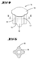
- FIGS. 4 and 5 is an example of a werkstükkes, here a rivet 15, shown, which can be produced with such a tool.
- the rivet has a rivet head 16 and a rivet shank 17.
- the rivet shank 17 is in its cross section, compare in particular Fig. 5 , out of shape.
Landscapes
- Engineering & Computer Science (AREA)
- Mechanical Engineering (AREA)
- Life Sciences & Earth Sciences (AREA)
- Agronomy & Crop Science (AREA)
- Forging (AREA)
- Insertion Pins And Rivets (AREA)
Description
- Die Erfindung betrifft zunächst ein Niet-Herstellungsvorrichtung und ein Verfahren zur Herstellung von Nieten.
- Bei einem bekannten Niet-Herstellungsvorrichtung und einem entsprechenden Verfahren siehe etwa
US 5,957,777 A1 , wird der Niet mittels relativ zueinander bewegter Flachwerkzeuge im Walzverfahren hergestellt. Darüber hinaus ist es aus derUS 4,084,303 bekannt, zum Abtrennen von walzenartigen Werkstücken aus einem stangenartigen Rohling an einem oder zwei miteinander in einem Werkzeugspalt zusammenwirkenden Werkzeugen schraubengangartig umlaufende Trenrisekuneiden auszubilden. Aus derUS 1,890,693 A1 ist es bekannt, zur Herstellung von Stahlkugeln zwei an Rotationsachsen umlaufende Umformwerkzeuge, von denen eines rotatorisch angetrieben ist, vorzusehen, wobei die Werkzeuge einen Walzspalt bilden und in jedem der Werkzeuge zugeordnete Walzkonturen ausgebildet sind, wobei die Walzkonturen schraubengangartig umlaufen, ohne Unterbrechung, unter Wandlung von einer Werkstück-Anfangskontur zu einer Werkstück-Endkontur, und wobei seitliche Werkstück-Abstützungen vorgesehen sind, wobei die Umformwerkzeuge übereinander angeordnet sind, so dass eines der Werkzeuge die unterseitige Abstützung erbringt, und wobei zudem die Werkzeugachsen parallel zueinander verlaufen. Die Erfindung beschäftigt sich mit der Aufgabe, ein vorteilhaftes Niet-Herstellungsvorrichtung anzugeben sowie ein vorteilhaftes Verfahren zur Herstellung von Nieten. - Diese Aufgabe ist beim Gegenstand des Anspruches 1 bzw. des Anspruches 8 gelöst. Die schraubengangartig umlaufende Walzkontur von einer Werkstück-Anfangskontur zu einer Werkstück-Endkontur lässt ohne Unterbrechung den gesamten Formungsvorgang von der Anfangskontur, dem Rohmaß, bis zu einer Niet-Endkontur, dem Endmaß, in dem Werkzeug durchführen. Das Rohmaß kann hierbei sehr viel größer gewählt werden, als es bei herkömmlichen Werkzeugen der Fall ist. Der Transport des Werkstückes ergibt sich von selbst durch die schraubengangartig umlaufende Kontur.
- In den Walzspalt der parallel zueinander verlaufenden Rotationsachsen der Umformwerkzeuge wird das Werkstück auf einer Seite eingeben. Es ergibt sich sogleich eine Selbstanziehung durch das Werkzeug und im Folgenden ein selbsttätiger Transport über die Länge des Walzspaltes und aus dem Walzspalt wieder heraus. Hierzu ist es vorteilhaft, wenn die Werkzeuge im Einzugsbereich jeweils eine Greifbeschichtung aufweisen. Die Greifbeschichtung kann unterschiedlich ausgebildet sein, bspw. in Form einer Diamantsplitterbeschichtung, wie dies etwa von Nagelfeilen bekannt ist.
- Unterhalb des Walzspaltes ist eine Werkstückabstützung ausgebildet. Diese ist bevorzugt schneidenartig. Andererseits kann je nach Geometrie des gewalzten Werkstückes eine besondere Anpassung erforderlich oder jedenfalls nützlich sein.
- Wesentlich ist auch, dass das Werkzeug eine Trennschneide ausbildet, zur Vereinzelung eines zunächst von einem Stangenrohling ausgehend umgeformten Werkstücks. Die Trennschneide ist geeigneterweise als Randbegrenzung einer Walzkontur vorgesehen. In die Vorrichtung kann also ein Stangenrohling gegeben werden, bzw. dieser wird von den Werkzeugen eingezogen, von dem dann abtrennend bzw. zunehmend abtrennend eine Auswalzung eines einzelnen Werkstückes erfolgt. Geeigneterweise erfolgt die letztliche Abtrennung erst im Bereich des letzten oder vorletzten Gewindeganges, in Durchsetzungsrichtung des Werkstückes durch die Vorrichtung gesehen.
- Weiter ist von Bedeutung, dass während des Transports die Umformung bis auf Fertigmaß vorgenommen wird.
- Darüber hinaus ist auch von Bedeutung, dass die Umformkontur Übergangslos vom Rohmaß bis zum Fertigmaß ausgebildet wird.
- Weiter ist auch verfahrensmäßig von Bedeutung, dass der Werkstückrohling stangenartig oder rohrartig ausgebildet ist, und dass durch eine an dem Werkzeug ausgeformte Trennschneide zugleich beim Durchsetzen des Werkstücks durch das Werkzeug eine Werkstücktrennung vorgenommen wird.
- Die Profilierung kann auch nur auf einer Teilabscbnittslänge vorgesehen sein. Sie kann symmetrisch auf beiden Werkzeugen vorgesehen sein oder unsymmetrisch auf dem einen oder anderen Werkzeug.
- Nachstehend ist die Erfindung des Weiteren anhand der beigefügten Zeichnung, die jedoch lediglich ein Ausführungsbeispiel darstellt, erläutert. Hierbei zeigt:
- Fig. 1
- eine Ansicht von oben der zugeordneten Werkzeuge, wobei eines der Werkzeuge geschnitten dargestellt ist;
- Fig. 2
- eine Vorderansicht der Werkzeuge;
- Fig. 3
- einen Querschnitt durch das Werkzeug 3, geschnitten entlang der Linie III-III;
- Fig. 4
- ein Beispiel eines konturierten Niets, hergestellt mit einem Werkzeug gemäß den
Figuren 1 bis 3 und - Fig. 5
- einen Querschnitt durch den Niet gemäß
Fig. 4 , geschnitten einer Linie V-V. - Dargestellt und beschrieben ist, zunächst mit Bezug zu
Fig. 1 , eine Vorrichtung zur Herstellung von Umformteilen wie beispielsweise einem Niet 1. Die Vorrichtung weist zwei rotatorisch angetriebene (der Antrieb ist nicht gesondert dargestellt) Umformwerkzeuge 2, 3 auf, die um Rotationsachsen 4, 5 umlaufen. Die Rotationsachsen verlaufen horizontal und parallel zueinander. - Die Werkzeuge 2, 3 bilden weiter einen Walzspalt 6 aus, der unterseitig eine Werkstückabstützung 7 (vergl.
Fig. 2 ) besitzt. Die Werkstückabstützumg 7 ist schneidenartig, an ihrem oberen Ende, ausgebildet. - Die Werkzeuge 2 , 3 weisen des Weiteren schraubengangartig umlaufende Walzkonturen 8, 9 auf.
- Wie aus
Fig. 1 ersichtlich, bildet eine Walzkontur 8 kontinuierlich ein Eingangsprofil 10 bis hin zu einem Endmaßprofil 11 aus. Durch die Profilierung wird ein Werkstück in den Walzspalt, sobald es die Werkzeuge 2, 3 berührt, aktiv eingezogen und durch den Walzspalt hindurch transportiert. Am Ende wird das Werkstück 1 auch sogleich selbsttätig aus der Vorrichtung ausgestoßen. - Von Bedeutung ist auch, dass die Vorrichtung - kontinuierlich anwachsende - als Langrandbegrenzung einer Walzkontur angeordnet. Trennschneiden 12 ausformt, die dazu führen, dass ein einzelnes Werkstück schließlich abgetrennt von den weiteren Werkstücken bzw. dem Rohling aus der Vorrichtung, nach Beendigung des Walzvorganges, ausgestoßen wird. Die Trennschneiden 12 sind beim Ausführungsbeispiel zugleich die Begrenzungen zwischen zwei nebeneinander liegenden Walzkonturen.
- Im Übrigen ist von Bedeutung, dass das Werkzeug im Einzugsbereich (vergleiche schraffierten Bereich im rechten Werkzeug in
Fig. 1 ) eine Diamantbeschichtung aufweist. Wie ersichtlich, kann sich die Diamantbeschichtung geeigneterweise über zwei oder drei Gewindegänge, in Tiefenrichtung des Werkzeugs gesehen, erstrekken. - Aus der Darstellung in
Fig. 3 ist ersichtlich, dass eine Walzkontur 8, über ihre Länge, d.h. folgend dem Gewindegang, profiliert ausgebildet ist. Es sind beispielsweise aufeinander abfolgende Berge 13 und Täler 14 zu erkennen. - Die Profilierung ist über die gesamte Länge einer Walzkontur 8 vorgesehen. Bevorzugt aber auch nur über einen Teilbereich, insbesondere den, in Durchsetzungsrichtung eines Werkstückes gesehen, End-Teilbereich der Walzkontur, da erst zum Ende der Umformung dann dem Werkstück diese Konturierung aufgeprägt wird.
- Weiter kann die Walzkonturierung symmetrisch bezüglich beider Werkzeuge vorgesehen sein, aber auch unsymmetrisch.
- In den
Figuren 4 und 5 ist ein Beispiel eines werkstükkes, hier ein Niet 15, dargestellt, das mit einem solchen Werkzeug hergestellt werden kann. Der Niet weist einen Nietkopf 16 und einen Nietschaft 17 auf. Der Nietschaft 17 ist in seinem Querschnitt, vergleiche insbesondereFig. 5 , unrund ausgebildet. Es sind im Querschnitt vorstehende Ausformungen 18 und Einbuchtungen 19 in Abfolge zu erkennen. Diese Konturierung lässt sich mit der bezüglichFig. 3 beschriebenen Profilierung im Walzverfahren erreichen.
Claims (10)
- Niet-Herstellungsvorrichtung (1) mit zwei an Rotationsachsen umlaufenden Umformwerkzeugen (2, 3) von denen mindestens eines rotatorisch angetrieben ist, wobei die Werkzeuge (2, 3) einen Walzspalt (6) bilden und in jedem der Werkzeuge (2, 3) zugeordnete Walzkonturen ausgebildet sind, wobei weiter die Walzkonturen schraubengangartig umlaufen, ohne Unterbrechung, unter Wandlung von einer Werkstück-Anfangskontur zu einer Werkstück-Eztdkontur, wobei weiter unterseitig des Walzspaltes (6) eine Werkstück-Abstützung (7) ausgebildet ist und die Werkzeugachsen parallel zueinander verlaufen, und wobei darüber hinaus die Walzkonturen (8, 9) über ihre Länge profiliert sind.
- Vorrichtung nach Anspruch 1, dadurch gekennzeichnet, dass der Walzspalt (6) horizontal verläuft.
- Vorrichtung nach einem der vorhergehenden Ansprüche, dadurch gekennzeichnet, dass das Werkzeug (2, 3) im Einzugsbereich eine Greifbeschichtung aufweist.
- Vorrichtung nach Anspruch 3, dadurch gekennzeichnet, dass die Greifbeschichtung durch Diamantsplitter gebildet ist.
- Vorrichtung nach einem der Ansprüche 1 bis 4, dadurch gekennzeichnet, dass die Werkstückabstützung (7), dem Walzspalt (6) zugeordnet, schneidenartig ausgeformt ist.
- Vorrichtung nach einem der Ansprüche 1 bis 5, dadurch gekennzeichnet, dass das Werkzeug (2, 3) eine Trennschneide (12) ausbildet zur Vereinzelung eines zunächst von einem Stangenrohling ausgehend umgeformten Werkstückes (1).
- Vorrichtung nach einem der Ansprüche 1 bis 6, dadurch gekennzeichnet, dass die Profilierung nur auf Teilabschnitten der Länge der Walzkontur ausgebildet ist.
- Verfahren zur Herstellung von Nieten in einer Vorrichtung mit zwei um Drehachsen umlaufende, zugeordnete Umformwerkzeuge, von denen mindestens eines rotatorisch angetrieben ist, wobei weiter ein Werkstück im Spalt zwischen den Werkzeugen durch in den Werkzeugen ausgebildete, zugeordnete schraubengangartige Umformkonturen transportiert wird, bei parallel zueinander verlaufenden Drehachsen, wobei weiter mit einer unterbrechungsfreien Walzkontur der gesamte Formungsvorgang von der Anfangskontur, dem Rohmaß, bis zu einer Werkstückendkontur, dem Fertigmaß, während des Transports in dem Spalt durchgeführt wird, und wobei darüber hinaus die Umformung mittels über ihre Länge profilierte Walzkonturen der beiden Werkzeuge durchgeführt wird.
- Verfahren nach Anspruch 8, dadurch gekennzeichnet, dass die Umformkontur übergangslos vom Rohmaß bis zum Fertigmaß ausgebildet wird.
- Verfahren nach einem der Ansprüche 8 oder 9, dadurch gekennzeichnet, dass der Werkstückrohling stangenartig oder rohrartig ausgebildet ist und dass durch eine an dem Werkzeug ausgeformte Trennschneide zugleich beim Durchsetzen des Werkstücks durch das Werkzeug eine Werkstücktrennung vorgenommen wird.
Applications Claiming Priority (2)
| Application Number | Priority Date | Filing Date | Title |
|---|---|---|---|
| DE10051866A DE10051866A1 (de) | 2000-10-19 | 2000-10-19 | Vorrichtung zur Herstellung von Umformteilen |
| DE10051866 | 2000-10-19 |
Publications (3)
| Publication Number | Publication Date |
|---|---|
| EP1199119A2 EP1199119A2 (de) | 2002-04-24 |
| EP1199119A3 EP1199119A3 (de) | 2003-07-23 |
| EP1199119B1 true EP1199119B1 (de) | 2010-03-10 |
Family
ID=7660348
Family Applications (1)
| Application Number | Title | Priority Date | Filing Date |
|---|---|---|---|
| EP01122725A Expired - Lifetime EP1199119B1 (de) | 2000-10-19 | 2001-09-21 | Niet- Herstellungsvorrichtung und Verfahren zur Herstellung von Nieten |
Country Status (3)
| Country | Link |
|---|---|
| EP (1) | EP1199119B1 (de) |
| AT (1) | ATE460242T1 (de) |
| DE (2) | DE10051866A1 (de) |
Families Citing this family (1)
| Publication number | Priority date | Publication date | Assignee | Title |
|---|---|---|---|---|
| DE102018003761A1 (de) * | 2018-05-09 | 2019-11-14 | Süddeutsche Gelenkscheibenfabrik GmbH & Co. KG | Verfahren zum Herstellen eines Statorträgers und Statorträger |
Citations (1)
| Publication number | Priority date | Publication date | Assignee | Title |
|---|---|---|---|---|
| US1890693A (en) * | 1930-01-09 | 1932-12-13 | Alexander C Munro | Ball forming machine |
Family Cites Families (8)
| Publication number | Priority date | Publication date | Assignee | Title |
|---|---|---|---|---|
| US2060087A (en) * | 1934-06-02 | 1936-11-10 | Timken Roller Bearing Co | Mill for rolling articles of circular section and irregular profile |
| AT291160B (de) * | 1966-12-16 | 1971-07-12 | Lajos Dipl Ing Balint | Verfahren und Maschine zur Herstellung von Rotationsformkörpern durch Walzen |
| US3602025A (en) * | 1968-03-01 | 1971-08-31 | Toyoda Chuo Kenkyusho Kk | Continuous transverse rolling process and apparatus |
| US3889516A (en) * | 1973-12-03 | 1975-06-17 | Colt Ind Operating Corp | Hardening coating for thread rolling dies |
| GB1528500A (en) * | 1976-01-07 | 1978-10-11 | Helipebs Ltd | Forming roll for rolling cylindrical metal bodies from cylindrical rod stock and a method of making the same |
| US5509287A (en) * | 1994-09-19 | 1996-04-23 | Anderson-Cook, Inc. | Method of conditioning the surface of a spline forming rack |
| DE19728736A1 (de) * | 1997-07-04 | 1999-01-07 | Rivet Technology P Ltd | Verfahren zum Herstellen von Befestigungselementen |
| DE10008659C5 (de) * | 1999-03-05 | 2011-06-30 | Kirsch, Jürgen, 42499 | Vorrichtung und Verfahren zur Herstellung eines Hohlteiles aus einem zylinderförmigen Rohling |
-
2000
- 2000-10-19 DE DE10051866A patent/DE10051866A1/de not_active Withdrawn
-
2001
- 2001-09-21 AT AT01122725T patent/ATE460242T1/de active
- 2001-09-21 DE DE50115379T patent/DE50115379D1/de not_active Expired - Lifetime
- 2001-09-21 EP EP01122725A patent/EP1199119B1/de not_active Expired - Lifetime
Patent Citations (1)
| Publication number | Priority date | Publication date | Assignee | Title |
|---|---|---|---|---|
| US1890693A (en) * | 1930-01-09 | 1932-12-13 | Alexander C Munro | Ball forming machine |
Also Published As
| Publication number | Publication date |
|---|---|
| ATE460242T1 (de) | 2010-03-15 |
| DE10051866A1 (de) | 2002-04-25 |
| EP1199119A2 (de) | 2002-04-24 |
| EP1199119A3 (de) | 2003-07-23 |
| DE50115379D1 (de) | 2010-04-22 |
Similar Documents
| Publication | Publication Date | Title |
|---|---|---|
| EP2385885B2 (de) | Vorrichtung und verfahren zum verzahnen von werkstücken | |
| DE2811567C3 (de) | Bohrschraube sowie Verfahren und Vorrichtung zu ihrer Herstellung | |
| EP2514546B1 (de) | Verfahren zum Formfräsen | |
| DE1910549C3 (de) | Kontinuierlich arbeitende Keilquerwalzvorrichtung | |
| WO1988000513A1 (en) | Process and device for producing turned parts from rods | |
| DE1552190A1 (de) | Verfahren und Vorrichtung zur Herstellung von Gegenstaenden durch Rollen | |
| DE3305034A1 (de) | Verfahren und vorrichtung zum herstellen eines gewindeschneidwerkzeugs | |
| DE2720822A1 (de) | Verfahren zum herstellen von gerade oder schraeg verzahnten maschinenelementen, insbesondere stirnzahnraedern, durch kaltumformen und vorrichtung zur durchfuehrung des verfahrens | |
| EP1967307A1 (de) | Verfahren zur Herstellung eines mit Nuten versehenen Rotornabenelementes | |
| DE420232C (de) | Gewindewalzmaschine mit zwei Gewindewalzen | |
| DE1138013B (de) | Verfahren und Vorrichtung zum Herstellen von an ihrem Umfang im wesentlichen laengsprofilierten zylindrischen Werkstuecken | |
| DE1477087A1 (de) | Verfahren und Vorrichtung zum Profilieren von Werkstuecken | |
| DE1652220C3 (de) | Verfahren zum spanabhebenden Bearbeiten eines Werkstücks | |
| DE102010041164B4 (de) | Verfahren zum Herstellen eines Bohrers | |
| DE2342145A1 (de) | Verfahren zum unterteilen eines langgestreckten gegenstandes | |
| EP1199119A2 (de) | Vorrichtung zur Herstellung von Umformteilen | |
| EP2994254B1 (de) | Verfahren und vorrichtung zum gewindewalzen mit walzrollen | |
| EP2327491A1 (de) | Verfahren zur Herstellung eines Bohrers und derart hergestellter Bohrer | |
| EP0616863B1 (de) | Verfahren zur Zahnstangenherstellung durch Kaltumformen, danach hergestellte Zahnstange und Vorrichtung zur Verfahrensdurchführung | |
| EP3248746B1 (de) | Tasteinrichtung für bearbeitungsaggregat, bearbeitungsvorrichtung und verfahren zum abtasten | |
| DE2129406A1 (de) | Verfahren zum Herstellen gewalzter Spiralbohrer und danach hergestellter Spiralbohrer | |
| DE704659C (de) | Walzverfahren zur Erzeugung von Blechen oder Profilen | |
| DE19836771A1 (de) | Formbearbeitungsverfahren, Verwendung desselben zum Herstellen von Formwerkzeugen und Angriffswerkzeug zur Verwendung darin | |
| EP3919246B1 (de) | Verfahren zur herstellung von holzstäben für verleimdübel | |
| DE4340162A1 (de) | Verfahren und Vorrichtung zum Gewindewalzen oder Glattwalzen von hülsen- oder bolzenförmigen Werkstücken |
Legal Events
| Date | Code | Title | Description |
|---|---|---|---|
| PUAI | Public reference made under article 153(3) epc to a published international application that has entered the european phase |
Free format text: ORIGINAL CODE: 0009012 |
|
| AK | Designated contracting states |
Kind code of ref document: A2 Designated state(s): AT BE CH CY DE DK ES FI FR GB GR IE IT LI LU MC NL PT SE TR |
|
| AX | Request for extension of the european patent |
Free format text: AL;LT;LV;MK;RO;SI |
|
| PUAL | Search report despatched |
Free format text: ORIGINAL CODE: 0009013 |
|
| AK | Designated contracting states |
Designated state(s): AT BE CH CY DE DK ES FI FR GB GR IE IT LI LU MC NL PT SE TR |
|
| AX | Request for extension of the european patent |
Extension state: AL LT LV MK RO SI |
|
| 17P | Request for examination filed |
Effective date: 20040108 |
|
| AKX | Designation fees paid |
Designated state(s): AT BE CH CY DE DK ES FI FR GB GR IE IT LI LU MC NL PT SE TR |
|
| 17Q | First examination report despatched |
Effective date: 20090129 |
|
| RTI1 | Title (correction) |
Free format text: DEVICE AND METHOD FOR MANUFACTURING RIVETS |
|
| GRAP | Despatch of communication of intention to grant a patent |
Free format text: ORIGINAL CODE: EPIDOSNIGR1 |
|
| GRAS | Grant fee paid |
Free format text: ORIGINAL CODE: EPIDOSNIGR3 |
|
| GRAA | (expected) grant |
Free format text: ORIGINAL CODE: 0009210 |
|
| AK | Designated contracting states |
Kind code of ref document: B1 Designated state(s): AT BE CH CY DE DK ES FI FR GB GR IE IT LI LU MC NL PT SE TR |
|
| REG | Reference to a national code |
Ref country code: GB Ref legal event code: FG4D Free format text: NOT ENGLISH |
|
| REG | Reference to a national code |
Ref country code: CH Ref legal event code: EP |
|
| REG | Reference to a national code |
Ref country code: IE Ref legal event code: FG4D |
|
| REF | Corresponds to: |
Ref document number: 50115379 Country of ref document: DE Date of ref document: 20100422 Kind code of ref document: P |
|
| REG | Reference to a national code |
Ref country code: NL Ref legal event code: VDEP Effective date: 20100310 |
|
| PG25 | Lapsed in a contracting state [announced via postgrant information from national office to epo] |
Ref country code: FI Free format text: LAPSE BECAUSE OF FAILURE TO SUBMIT A TRANSLATION OF THE DESCRIPTION OR TO PAY THE FEE WITHIN THE PRESCRIBED TIME-LIMIT Effective date: 20100310 |
|
| REG | Reference to a national code |
Ref country code: IE Ref legal event code: FD4D |
|
| PG25 | Lapsed in a contracting state [announced via postgrant information from national office to epo] |
Ref country code: ES Free format text: LAPSE BECAUSE OF FAILURE TO SUBMIT A TRANSLATION OF THE DESCRIPTION OR TO PAY THE FEE WITHIN THE PRESCRIBED TIME-LIMIT Effective date: 20100621 Ref country code: NL Free format text: LAPSE BECAUSE OF FAILURE TO SUBMIT A TRANSLATION OF THE DESCRIPTION OR TO PAY THE FEE WITHIN THE PRESCRIBED TIME-LIMIT Effective date: 20100310 Ref country code: SE Free format text: LAPSE BECAUSE OF FAILURE TO SUBMIT A TRANSLATION OF THE DESCRIPTION OR TO PAY THE FEE WITHIN THE PRESCRIBED TIME-LIMIT Effective date: 20100310 Ref country code: GR Free format text: LAPSE BECAUSE OF FAILURE TO SUBMIT A TRANSLATION OF THE DESCRIPTION OR TO PAY THE FEE WITHIN THE PRESCRIBED TIME-LIMIT Effective date: 20100611 Ref country code: CY Free format text: LAPSE BECAUSE OF FAILURE TO SUBMIT A TRANSLATION OF THE DESCRIPTION OR TO PAY THE FEE WITHIN THE PRESCRIBED TIME-LIMIT Effective date: 20100310 |
|
| PLBE | No opposition filed within time limit |
Free format text: ORIGINAL CODE: 0009261 |
|
| STAA | Information on the status of an ep patent application or granted ep patent |
Free format text: STATUS: NO OPPOSITION FILED WITHIN TIME LIMIT |
|
| PG25 | Lapsed in a contracting state [announced via postgrant information from national office to epo] |
Ref country code: DK Free format text: LAPSE BECAUSE OF FAILURE TO SUBMIT A TRANSLATION OF THE DESCRIPTION OR TO PAY THE FEE WITHIN THE PRESCRIBED TIME-LIMIT Effective date: 20100310 Ref country code: PT Free format text: LAPSE BECAUSE OF FAILURE TO SUBMIT A TRANSLATION OF THE DESCRIPTION OR TO PAY THE FEE WITHIN THE PRESCRIBED TIME-LIMIT Effective date: 20100712 Ref country code: IE Free format text: LAPSE BECAUSE OF FAILURE TO SUBMIT A TRANSLATION OF THE DESCRIPTION OR TO PAY THE FEE WITHIN THE PRESCRIBED TIME-LIMIT Effective date: 20100310 |
|
| 26N | No opposition filed |
Effective date: 20101213 |
|
| BERE | Be: lapsed |
Owner name: SCHMITZ, HANS-GERT Effective date: 20100930 Owner name: KIRSCH, JURGEN Effective date: 20100930 |
|
| PG25 | Lapsed in a contracting state [announced via postgrant information from national office to epo] |
Ref country code: IT Free format text: LAPSE BECAUSE OF FAILURE TO SUBMIT A TRANSLATION OF THE DESCRIPTION OR TO PAY THE FEE WITHIN THE PRESCRIBED TIME-LIMIT Effective date: 20100310 |
|
| PG25 | Lapsed in a contracting state [announced via postgrant information from national office to epo] |
Ref country code: MC Free format text: LAPSE BECAUSE OF NON-PAYMENT OF DUE FEES Effective date: 20100930 |
|
| PG25 | Lapsed in a contracting state [announced via postgrant information from national office to epo] |
Ref country code: BE Free format text: LAPSE BECAUSE OF NON-PAYMENT OF DUE FEES Effective date: 20100930 |
|
| PG25 | Lapsed in a contracting state [announced via postgrant information from national office to epo] |
Ref country code: LU Free format text: LAPSE BECAUSE OF NON-PAYMENT OF DUE FEES Effective date: 20100921 |
|
| PG25 | Lapsed in a contracting state [announced via postgrant information from national office to epo] |
Ref country code: TR Free format text: LAPSE BECAUSE OF FAILURE TO SUBMIT A TRANSLATION OF THE DESCRIPTION OR TO PAY THE FEE WITHIN THE PRESCRIBED TIME-LIMIT Effective date: 20100310 |
|
| PGFP | Annual fee paid to national office [announced via postgrant information from national office to epo] |
Ref country code: FR Payment date: 20120927 Year of fee payment: 12 |
|
| PGFP | Annual fee paid to national office [announced via postgrant information from national office to epo] |
Ref country code: CH Payment date: 20121009 Year of fee payment: 12 |
|
| PGFP | Annual fee paid to national office [announced via postgrant information from national office to epo] |
Ref country code: GB Payment date: 20121009 Year of fee payment: 12 |
|
| PGFP | Annual fee paid to national office [announced via postgrant information from national office to epo] |
Ref country code: AT Payment date: 20120919 Year of fee payment: 12 |
|
| PGFP | Annual fee paid to national office [announced via postgrant information from national office to epo] |
Ref country code: DE Payment date: 20140328 Year of fee payment: 13 |
|
| REG | Reference to a national code |
Ref country code: CH Ref legal event code: PL |
|
| REG | Reference to a national code |
Ref country code: AT Ref legal event code: MM01 Ref document number: 460242 Country of ref document: AT Kind code of ref document: T Effective date: 20130921 |
|
| GBPC | Gb: european patent ceased through non-payment of renewal fee |
Effective date: 20130921 |
|
| REG | Reference to a national code |
Ref country code: FR Ref legal event code: ST Effective date: 20140530 |
|
| PG25 | Lapsed in a contracting state [announced via postgrant information from national office to epo] |
Ref country code: GB Free format text: LAPSE BECAUSE OF NON-PAYMENT OF DUE FEES Effective date: 20130921 Ref country code: CH Free format text: LAPSE BECAUSE OF NON-PAYMENT OF DUE FEES Effective date: 20130930 Ref country code: LI Free format text: LAPSE BECAUSE OF NON-PAYMENT OF DUE FEES Effective date: 20130930 |
|
| PG25 | Lapsed in a contracting state [announced via postgrant information from national office to epo] |
Ref country code: AT Free format text: LAPSE BECAUSE OF NON-PAYMENT OF DUE FEES Effective date: 20130921 Ref country code: FR Free format text: LAPSE BECAUSE OF NON-PAYMENT OF DUE FEES Effective date: 20130930 |
|
| REG | Reference to a national code |
Ref country code: DE Ref legal event code: R119 Ref document number: 50115379 Country of ref document: DE |
|
| REG | Reference to a national code |
Ref country code: DE Ref legal event code: R119 Ref document number: 50115379 Country of ref document: DE Effective date: 20150401 |
|
| PG25 | Lapsed in a contracting state [announced via postgrant information from national office to epo] |
Ref country code: DE Free format text: LAPSE BECAUSE OF NON-PAYMENT OF DUE FEES Effective date: 20150401 |