EP1198031A2 - Verbinder mit verstärkender Struktur zum Befestigen des Verbindergehäuses an einer Leiterplatte - Google Patents
Verbinder mit verstärkender Struktur zum Befestigen des Verbindergehäuses an einer Leiterplatte Download PDFInfo
- Publication number
- EP1198031A2 EP1198031A2 EP01124533A EP01124533A EP1198031A2 EP 1198031 A2 EP1198031 A2 EP 1198031A2 EP 01124533 A EP01124533 A EP 01124533A EP 01124533 A EP01124533 A EP 01124533A EP 1198031 A2 EP1198031 A2 EP 1198031A2
- Authority
- EP
- European Patent Office
- Prior art keywords
- housing
- fixed
- connector
- reinforcing metal
- parts
- Prior art date
- Legal status (The legal status is an assumption and is not a legal conclusion. Google has not performed a legal analysis and makes no representation as to the accuracy of the status listed.)
- Withdrawn
Links
Images


Classifications
-
- H—ELECTRICITY
- H01—ELECTRIC ELEMENTS
- H01R—ELECTRICALLY-CONDUCTIVE CONNECTIONS; STRUCTURAL ASSOCIATIONS OF A PLURALITY OF MUTUALLY-INSULATED ELECTRICAL CONNECTING ELEMENTS; COUPLING DEVICES; CURRENT COLLECTORS
- H01R12/00—Structural associations of a plurality of mutually-insulated electrical connecting elements, specially adapted for printed circuits, e.g. printed circuit boards [PCB], flat or ribbon cables, or like generally planar structures, e.g. terminal strips, terminal blocks; Coupling devices specially adapted for printed circuits, flat or ribbon cables, or like generally planar structures; Terminals specially adapted for contact with, or insertion into, printed circuits, flat or ribbon cables, or like generally planar structures
- H01R12/70—Coupling devices
- H01R12/7005—Guiding, mounting, polarizing or locking means; Extractors
- H01R12/7011—Locking or fixing a connector to a PCB
- H01R12/707—Soldering or welding
-
- H—ELECTRICITY
- H01—ELECTRIC ELEMENTS
- H01R—ELECTRICALLY-CONDUCTIVE CONNECTIONS; STRUCTURAL ASSOCIATIONS OF A PLURALITY OF MUTUALLY-INSULATED ELECTRICAL CONNECTING ELEMENTS; COUPLING DEVICES; CURRENT COLLECTORS
- H01R12/00—Structural associations of a plurality of mutually-insulated electrical connecting elements, specially adapted for printed circuits, e.g. printed circuit boards [PCB], flat or ribbon cables, or like generally planar structures, e.g. terminal strips, terminal blocks; Coupling devices specially adapted for printed circuits, flat or ribbon cables, or like generally planar structures; Terminals specially adapted for contact with, or insertion into, printed circuits, flat or ribbon cables, or like generally planar structures
- H01R12/70—Coupling devices
- H01R12/77—Coupling devices for flexible printed circuits, flat or ribbon cables or like structures
- H01R12/79—Coupling devices for flexible printed circuits, flat or ribbon cables or like structures connecting to rigid printed circuits or like structures
-
- H—ELECTRICITY
- H01—ELECTRIC ELEMENTS
- H01R—ELECTRICALLY-CONDUCTIVE CONNECTIONS; STRUCTURAL ASSOCIATIONS OF A PLURALITY OF MUTUALLY-INSULATED ELECTRICAL CONNECTING ELEMENTS; COUPLING DEVICES; CURRENT COLLECTORS
- H01R13/00—Details of coupling devices of the kinds covered by groups H01R12/70 or H01R24/00 - H01R33/00
- H01R13/62—Means for facilitating engagement or disengagement of coupling parts or for holding them in engagement
- H01R13/639—Additional means for holding or locking coupling parts together, after engagement, e.g. separate keylock, retainer strap
-
- H—ELECTRICITY
- H01—ELECTRIC ELEMENTS
- H01R—ELECTRICALLY-CONDUCTIVE CONNECTIONS; STRUCTURAL ASSOCIATIONS OF A PLURALITY OF MUTUALLY-INSULATED ELECTRICAL CONNECTING ELEMENTS; COUPLING DEVICES; CURRENT COLLECTORS
- H01R12/00—Structural associations of a plurality of mutually-insulated electrical connecting elements, specially adapted for printed circuits, e.g. printed circuit boards [PCB], flat or ribbon cables, or like generally planar structures, e.g. terminal strips, terminal blocks; Coupling devices specially adapted for printed circuits, flat or ribbon cables, or like generally planar structures; Terminals specially adapted for contact with, or insertion into, printed circuits, flat or ribbon cables, or like generally planar structures
- H01R12/50—Fixed connections
- H01R12/51—Fixed connections for rigid printed circuits or like structures
- H01R12/55—Fixed connections for rigid printed circuits or like structures characterised by the terminals
- H01R12/57—Fixed connections for rigid printed circuits or like structures characterised by the terminals surface mounting terminals
-
- H—ELECTRICITY
- H01—ELECTRIC ELEMENTS
- H01R—ELECTRICALLY-CONDUCTIVE CONNECTIONS; STRUCTURAL ASSOCIATIONS OF A PLURALITY OF MUTUALLY-INSULATED ELECTRICAL CONNECTING ELEMENTS; COUPLING DEVICES; CURRENT COLLECTORS
- H01R12/00—Structural associations of a plurality of mutually-insulated electrical connecting elements, specially adapted for printed circuits, e.g. printed circuit boards [PCB], flat or ribbon cables, or like generally planar structures, e.g. terminal strips, terminal blocks; Coupling devices specially adapted for printed circuits, flat or ribbon cables, or like generally planar structures; Terminals specially adapted for contact with, or insertion into, printed circuits, flat or ribbon cables, or like generally planar structures
- H01R12/70—Coupling devices
- H01R12/7005—Guiding, mounting, polarizing or locking means; Extractors
- H01R12/7011—Locking or fixing a connector to a PCB
Definitions
- the present invention relates to an on-board type connector which is adapted to be mounted on a circuit board.
- the on-board type connector is constructed in such a manner that its terminals are respectively provided with leg portions, and the leg portions are connected to and fixed on the circuit board by soldering or so.
- the connector only by means of soldering between the leg portions of the terminals and the circuit board, high connection reliability cannot be obtained, because an outer force exerted on the relevant connector will be transferred as it is, to the soldered parts (terminal connecting parts) and will cause a large overload in strength on the soldered parts.
- a connector illustrated on the drawings is intended to electrically connect a flat wiring member 40 which is flat and flexible, to a circuit board C as shown in Fig. 10.
- the connector includes a number of terminals 10, a housing 20 for holding the terminals, and a slider 30 attached to this housing 20.
- Each of the terminals 10 is formed of conductive material such as metal, and integrally has a leg portion 12 in a substantially L-shape which is mounted on the circuit board C as shown in Fig. 10, an upper horizontal portion 14 horizontally extending from an upper end of the leg portion 12, a lower horizontal portion 16 branched off downward from a base end of the upper horizontal portion 14 and extending in parallel to the upper horizontal portion 14, and a conductor contacting portion 18 which is turned back from an end of the lower horizontal portion 16 at an acute angle.
- These terminals 10 are held by the housing 20 in such a manner that they are directed in a back and forth direction and arranged in a row in a lateral direction.
- the housing 20 is integrally molded of synthetic resin in its entirety, and has a body part 21 which extends laterally, and a top wall part 22 which extends in parallel to the body part 21 above a backward half part of the body part 21. These body part 21 and top wall part 22 are connected vertically at a back part, and left and right sides of the housing.
- the body part 21 is formed with terminal containing grooves 21a extending in a back and forth direction which are adapted to contain the lower horizontal portions 16 of the aforesaid terminals 10, so that the conductor contacting portions 18 of the terminals 10 may project upward from the terminal containing grooves 21a.
- terminal insertion grooves 22a into which the upper horizontal portions 14 of the terminals 10 are respectively inserted.
- the slider 30 is also integrally formed of insulating material, and has a shape of extending in a lateral direction of the flat wiring member 40. More specifically, the slider 30 integrally has a pair of left and right side walls 32 extending in a back and forth direction, and a laterally extending connecting part 34 which connects both the side walls 32. A wiring member holding piece 35 extends backward from the connecting part 34. There are further formed, on inner faces of both the side walls 32, lockable portions 36 which project inwardly.
- an insulating layer on its lower face is peeled off to expose an inner conductor at its lower side, and a reinforcing plate 42 is fixed to an upper face of the end by means of boding or the like.
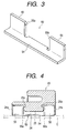
- each of the reinforcing metal plates 50 is formed of a single metal plate by bending work, and integrally has a part 51 to be fixed on the circuit board C, and a part 52 to be fixed to the housing which is erected upward from a side of a backward end of the part 51 to be fixed on the board. There is formed a cut-out 52a at a middle position of a front edge of the part 52 to be fixed to the housing.
- the reinforcing metal plate 50 By press fitting the parts 52 of the reinforcing metal plate 50 to be fixed to the housing into the slits 23 from the back side (in other words, by press fitting the projections 23a into the cut-outs 52a), the reinforcing metal plate 50 is fixed to the housing 20. Then, by fixing the parts 51 to be fixed on the board in this reinforcing metal plate 50 to the circuit board C which is not shown in the drawing, by soldering or so, the overload in strength exerted on the connecting positions between the leg portions of the terminals 10 and the circuit board C can be reduced.
- the above described connector particularly the connector for an automobile has come to have multi-contacts, and accordingly, requires a larger force than ever for inserting and detaching the slider 30 as described above or a connector to be mated.
- the parts 52 of the reinforcing metal plate 50 to be fixed to the housing are inserted into the slits 23 of the housing 20 from the back side. Accordingly, it is difficult to withstand a force of pulling the housing 20 forward, that is, a force exerted on the housing 20 (a leftward force in Figs.
- an object of the invention to provide an on-board type connector which is simple in structure, and in which an overload in strength exerted on connecting positions between terminals and a circuit board can be effectively reduced, even when a slider or a connector to be mated is connected to or detached from a housing.
- an on-board type connector comprising a housing made of synthetic resin which holds a plurality of terminals to be connected to a circuit board in such a manner that the terminals are directed in a back and forth direction and laterally arranged, and two reinforcing metal plates fixed to both sides of the housing in a lateral direction, the reinforcing metal plates integrally having parts to be fixed to both sides of the housing made of synthetic resin in the lateral direction and parts to be fixed on the circuit board, characterized in that the housing is provided, at both sides thereof in the lateral direction, with insertion slits which open toward a bottom face of the housing, and into which the parts to be fixed to the housing are inserted from the bottom face and fixed, the insertion slits being so shaped that the parts to be fixed to the housing which have been inserted into the slits are restrained by the housing from both a front and a back sides.
- the overload in strength exerted on the connecting positions between the relevant circuit board and the terminals can be reduced, by fixing the parts of the reinforcing metal plates to be fixed on the circuit board on the relevant circuit board in a state where the reinforcing metal plates are inserted into the insertion slits which are formed in the housing and fixed.
- the insertion slits open toward the bottom face of the housing, and the parts to be fixed to the housing are inserted from the bottom face and fixed, to be restrained by the housing from both the front and the back sides. Therefore, an outer force applied to the terminals and the housing when the slider or the connector to be mated is inserted or detached can be sufficiently withstood, and the overload in strength exerted on the connecting positions between the terminals and the circuit board can be effectively reduced.
- the parts of the reinforcing metal plate to be fixed to the housing may be formed at both sides of the relevant reinforcing metal plate in a back and forth direction, while the insertion slits may be formed at both forward and backward sides of the housing, and a restraining part adapted to restrain the parts to be fixed to the housing from inside may be formed at an intermediate position between the insertion slits.
- the parts to be fixed to the housing are inserted at both sides of the housing in the back and forth direction, effective reinforcement can be attained along an entire area in the back and forth direction. Furthermore, the part of the housing (the restraining part) interposed between both the parts to be fixed to the housing can effectively restrain the parts to be fixed to the housing from both the back and the forth.
- the two reinforcing metal plates are constructed so that they may have a shape identical to each other, mass production can be promoted, and the cost can be reduced.
- the two reinforcing metal plates have a symmetrical shape as seen in the lateral direction of the housing, common use of the two reinforcing metal plates can be realized while maintaining a balanced structure.
- the parts to be fixed to the housing may be provided on their surfaces with hooks which are adapted to be engaged with inner walls of the slits. By engaging the hooks in this manner, reliable fixation can be attained with a simple structure.
- FIG. 1 to 5 A first embodiment of the invention will be described referring to Figs. 1 to 5.
- This embodiment is substantially equal to the above described example as shown in Figs. 9 to 11, except the shape of the reinforcing metal plate 50 and the structure wherein the reinforcing metal plate 50 is fixed to the housing 20, and so, the relevant explanation will be omitted here.
- slits 24 which open backward, at both sides of the housing 20 in a lateral direction.
- restraining portions 25a for delimiting both end portions of the back and forth direction.
- the both end portions of the back and forth direction delimited by the restraining portions 25a are designed as insertion slits 24a.
- dented parts 25a which are dented toward a center of the restraining part 25.
- This slit 24 can be formed in the housing 20, as shown by phantom lines in Fig.
- molds 60A and 60B including parts 62A, 62B each having a shape of the slit 24 cut into halves at an intermediate position in the back and forth direction, and by extracting the molds 60A and 60B to the back and the forth.
- the reinforcing metal plate 50 is formed of a single metal plate by bending work, and integrally has a part 54 to be fixed on the board which extends along the entire length of the housing in a back and forth direction, and a pair of parts 55 to be fixed to the housing which are erected upward from both sides of the part 54 in a back and forth direction.
- Each of the parts 55 to be fixed to the housing has such a shape as capable of being inserted into each of the insertion slits 24a.
- the parts 55 to be fixed to the housing are inserted into the insertion slits 24a of the housing 20 from a bottom face side of the housing, and are restrained from the back and the forth by means of the restraining part 25 which is interposed between both the parts 55 to be fixed to the housing. Consequently, an outer force applied to the housing 20 when the slide 30 is inserted and detached in the back and forth direction can be sufficiently withstood, and the connecting positions of the leg portions 12 can be effectively protected.
- the slit 24 is not necessarily formed along the entire length of the housing 20 in the back and forth direction, but may be in a shape completely divided to the back and the forth by the restraining part 25.
- the insertion slits 24a had better be so shaped that they may open toward the back and the forth of the housing 20 in the same manner as in the illustrated structure, and so, the molds 60A, 608 can be extracted in the back and forth direction (that is, a direction parallel to an insertion direction of the terminals) as shown in Fig. 2.
- the structure has an advantage that installation of the molds will be simplified.
- each of the reinforcing metal plates 50 may be shaped symmetrically as seen in a lateral direction of the housing, and the two reinforcing metal plates 50 having the same shape can be employed, as shown in the drawings.
- mass production can be promoted, and the manufacturing cost can be further reduced.
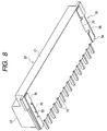
- FIG. 6 to 8 A second embodiment is shown in Figs. 6 to 8.
- an insertion slit 26 is formed at an intermediate position of the housing 20 in a back and forth direction.
- a part 56 to be fixed to the housing which is adapted to be inserted into the insertion slit 26 is erected upward from an intermediate position of the part 54 of the reinforcing metal plate 50 to be fixed on the board.
- the part 56 to be fixed to the housing is provided with hooks 56a projected from upper ends of both backward and forward end faces thereof.
- the part 56 to be fixed to the housing is so adapted to be fixed to the housing 20, when the hooks 56a bite into inner walls of the insertion slit 26.
- parts of the housing 20 located in the front and the back of the insertion slit 26 constitute restraining parts 27 which restrain the aforesaid part 56 to be fixed to the housing from the front and the back. Accordingly, an outer force applied to the housing 20 when the slide 30 is inserted and detached in the back and forth direction can be sufficiently withstood.
- the aforesaid parts 55 to be fixed to the housing are constructed to be positioned at both sides of the housing in the back and forth direction, as shown in the first embodiment. If so constructed, the housing 20 can be reinforced at both the front and back sides, and therefore, a connector which is more favorable in strength can be realized.
- the on-board type connector according to the invention is not limited to this type, but can be applied to an ordinary connector in which a housing of a mating connector is engaged with the housing 20. In this case too, an effect of withstanding an outer force in the back and forth direction exerted when the mating connector is inserted and detached can be obtained.
- the insertion slits which open toward the bottom face of the housing and into which the parts to be fixed to the housing are inserted and fixed.
- Each of the slits is so shaped that the part to be fixed to the housing which has been press inserted into the slit may be restrained by the housing from the front and the back. Therefore, it is possible to attain effective reinforcement against an outer force in the back and forth direction with a simple structure, and accordingly, it is advantageous that the overload in strength exerted on the connecting positions between the terminals and the circuit board when the slider and so on is connected to and detached from the housing can be effectively reduced.
Landscapes
- Coupling Device And Connection With Printed Circuit (AREA)
Applications Claiming Priority (2)
| Application Number | Priority Date | Filing Date | Title |
|---|---|---|---|
| JP2000313434 | 2000-10-13 | ||
| JP2000313434A JP2002124329A (ja) | 2000-10-13 | 2000-10-13 | 基板実装型コネクタ |
Publications (2)
| Publication Number | Publication Date |
|---|---|
| EP1198031A2 true EP1198031A2 (de) | 2002-04-17 |
| EP1198031A3 EP1198031A3 (de) | 2004-05-26 |
Family
ID=18792853
Family Applications (1)
| Application Number | Title | Priority Date | Filing Date |
|---|---|---|---|
| EP01124533A Withdrawn EP1198031A3 (de) | 2000-10-13 | 2001-10-12 | Verbinder mit verstärkender Struktur zum Befestigen des Verbindergehäuses an einer Leiterplatte |
Country Status (3)
| Country | Link |
|---|---|
| US (1) | US6699069B2 (de) |
| EP (1) | EP1198031A3 (de) |
| JP (1) | JP2002124329A (de) |
Cited By (5)
| Publication number | Priority date | Publication date | Assignee | Title |
|---|---|---|---|---|
| WO2004010538A1 (en) * | 2002-07-23 | 2004-01-29 | Matsushita Electric Works, Ltd. | Low-profile connector |
| WO2004021518A1 (en) * | 2002-08-30 | 2004-03-11 | Molex Incorporated | Electrical connector for interconnecting flat circuits |
| EP1724879A1 (de) * | 2005-05-20 | 2006-11-22 | Sumitomo Wiring Systems, Ltd. | Steckverbinder zur Montage auf einem elektrischen/elektronischen Gerät |
| CN100409493C (zh) * | 2002-08-30 | 2008-08-06 | 莫列斯公司 | 用于互接平板电路的电连接器 |
| CN111527649A (zh) * | 2018-01-12 | 2020-08-11 | 科世达接触系统有限公司 | 插塞连接器装置 |
Families Citing this family (11)
| Publication number | Priority date | Publication date | Assignee | Title |
|---|---|---|---|---|
| JP3969229B2 (ja) * | 2002-07-23 | 2007-09-05 | 松下電工株式会社 | コネクタ |
| JP2004273270A (ja) * | 2003-03-07 | 2004-09-30 | Jst Mfg Co Ltd | 電気コネクタ |
| JP4013914B2 (ja) * | 2004-04-12 | 2007-11-28 | 住友電装株式会社 | 基板用コネクタ |
| JP4498914B2 (ja) * | 2004-12-27 | 2010-07-07 | 矢崎総業株式会社 | 固定金具 |
| US7064296B1 (en) * | 2005-03-15 | 2006-06-20 | Culinary Logic, Llc | Oven with an articulating and retractable door |
| JP4262708B2 (ja) * | 2005-09-26 | 2009-05-13 | 住友電装株式会社 | 基板用コネクタ |
| JP4768588B2 (ja) * | 2006-11-29 | 2011-09-07 | 株式会社オートネットワーク技術研究所 | 表面実装コネクタが実装された回路基板 |
| JP5233959B2 (ja) * | 2009-11-05 | 2013-07-10 | 住友電装株式会社 | 機器用コネクタ |
| JP5251840B2 (ja) * | 2009-11-17 | 2013-07-31 | 住友電装株式会社 | 機器用コネクタ |
| JP5641345B2 (ja) * | 2011-03-15 | 2014-12-17 | 住友電装株式会社 | 機器用コネクタ |
| JP5885080B2 (ja) * | 2012-12-25 | 2016-03-15 | 住友電装株式会社 | 基板用コネクタ |
Citations (7)
| Publication number | Priority date | Publication date | Assignee | Title |
|---|---|---|---|---|
| US4640562A (en) * | 1984-12-19 | 1987-02-03 | Amp Incorporated | Surface mounting means for printed circuit board |
| US5194017A (en) * | 1992-02-24 | 1993-03-16 | Amp Incorporated | Connector for a flexible circuit |
| US5259789A (en) * | 1993-02-23 | 1993-11-09 | Molex Incorporated | Retention system for circuit board mounted electrical connector |
| US5354214A (en) * | 1993-07-23 | 1994-10-11 | Molex Incorporated | Printed circuit board electrical connector with mounting latch clip |
| US5395265A (en) * | 1991-07-16 | 1995-03-07 | Berg Technology, Inc. | Retention system for a connector housing |
| GB2282495A (en) * | 1993-09-20 | 1995-04-05 | Sumitomo Wiring Systems | Retaining surface-mount connectors |
| US6030249A (en) * | 1996-08-08 | 2000-02-29 | Itt Manufacturing Enterprises, Inc. | Molded connector with metal holder |
Family Cites Families (6)
| Publication number | Priority date | Publication date | Assignee | Title |
|---|---|---|---|---|
| US5626482A (en) * | 1994-12-15 | 1997-05-06 | Molex Incorporated | Low profile surface mountable electrical connector assembly |
| WO1997022164A1 (en) * | 1995-12-11 | 1997-06-19 | The Whitaker Corporation | Surface mountable retention bracket for electrical connectors |
| US6042420A (en) * | 1999-02-23 | 2000-03-28 | The Whitaker Corporation | Electrical connector and boardlock with minimal footprint |
| US6152765A (en) * | 1999-05-04 | 2000-11-28 | Hon Hai Precision Ind. Co., Ltd. | Electrical connector |
| US6227906B1 (en) * | 1999-12-21 | 2001-05-08 | Hon Nai Precision Ind. Co., Ltd. | Connector to circuit board securing arrangement |
| US6231386B1 (en) * | 1999-12-29 | 2001-05-15 | Hon Hai Precision Ind. Co., Ltd. | Electrical connector with improved solder pads |
-
2000
- 2000-10-13 JP JP2000313434A patent/JP2002124329A/ja not_active Withdrawn
-
2001
- 2001-10-10 US US09/972,861 patent/US6699069B2/en not_active Expired - Fee Related
- 2001-10-12 EP EP01124533A patent/EP1198031A3/de not_active Withdrawn
Patent Citations (8)
| Publication number | Priority date | Publication date | Assignee | Title |
|---|---|---|---|---|
| US4640562A (en) * | 1984-12-19 | 1987-02-03 | Amp Incorporated | Surface mounting means for printed circuit board |
| US5395265A (en) * | 1991-07-16 | 1995-03-07 | Berg Technology, Inc. | Retention system for a connector housing |
| US5194017A (en) * | 1992-02-24 | 1993-03-16 | Amp Incorporated | Connector for a flexible circuit |
| US5259789A (en) * | 1993-02-23 | 1993-11-09 | Molex Incorporated | Retention system for circuit board mounted electrical connector |
| US5354214A (en) * | 1993-07-23 | 1994-10-11 | Molex Incorporated | Printed circuit board electrical connector with mounting latch clip |
| GB2282495A (en) * | 1993-09-20 | 1995-04-05 | Sumitomo Wiring Systems | Retaining surface-mount connectors |
| US5928031A (en) * | 1993-09-20 | 1999-07-27 | Sumitomo Wiring Systems, Ltd. | Surface-mount connector |
| US6030249A (en) * | 1996-08-08 | 2000-02-29 | Itt Manufacturing Enterprises, Inc. | Molded connector with metal holder |
Cited By (9)
| Publication number | Priority date | Publication date | Assignee | Title |
|---|---|---|---|---|
| WO2004010538A1 (en) * | 2002-07-23 | 2004-01-29 | Matsushita Electric Works, Ltd. | Low-profile connector |
| US6986670B2 (en) | 2002-07-23 | 2006-01-17 | Matsushita Electric Works, Ltd. | Low-profile connector |
| US7112091B2 (en) | 2002-07-23 | 2006-09-26 | Matsushita Electric Works, Ltd. | Low-profile connector |
| WO2004021518A1 (en) * | 2002-08-30 | 2004-03-11 | Molex Incorporated | Electrical connector for interconnecting flat circuits |
| CN100409493C (zh) * | 2002-08-30 | 2008-08-06 | 莫列斯公司 | 用于互接平板电路的电连接器 |
| EP1724879A1 (de) * | 2005-05-20 | 2006-11-22 | Sumitomo Wiring Systems, Ltd. | Steckverbinder zur Montage auf einem elektrischen/elektronischen Gerät |
| CN111527649A (zh) * | 2018-01-12 | 2020-08-11 | 科世达接触系统有限公司 | 插塞连接器装置 |
| US11101599B2 (en) | 2018-01-12 | 2021-08-24 | Kostal Kontakt Systeme Gmbh | Plug connector assembly |
| CN111527649B (zh) * | 2018-01-12 | 2022-01-21 | 科世达接触系统有限公司 | 插塞连接器装置 |
Also Published As
| Publication number | Publication date |
|---|---|
| US6699069B2 (en) | 2004-03-02 |
| JP2002124329A (ja) | 2002-04-26 |
| US20020045367A1 (en) | 2002-04-18 |
| EP1198031A3 (de) | 2004-05-26 |
Similar Documents
| Publication | Publication Date | Title |
|---|---|---|
| US7252549B2 (en) | Connector, receptacle for connector and plug for connector | |
| US9397423B2 (en) | Board-to-board connector | |
| US6699069B2 (en) | On-board type connector | |
| US4571017A (en) | Electrical connector assembly | |
| US6358089B1 (en) | Connector for printed wiring board | |
| EP1503461B1 (de) | Verbinderkombination | |
| EP2592699B1 (de) | Stecker und steckerverbindender Körper | |
| US5161985A (en) | Board to board interconnect | |
| US6364718B1 (en) | Keying system for electrical connector assemblies | |
| US7470153B2 (en) | Audio jack with improved contact arrangement | |
| US6736655B2 (en) | Rack and pinion electrical connector with offset gear teeth | |
| US6315591B2 (en) | Electrical connector having an improved female contact | |
| US20050032406A1 (en) | Floating connector | |
| JP3647951B2 (ja) | 一対の嵌合コンタクトおよび電気コネクタ組立体 | |
| US20110250793A1 (en) | Electrical Connector | |
| EP1235303A2 (de) | Ein Steckverbinder und ein Verfahren für seine Herstellung | |
| JP4162214B2 (ja) | 電気コネクタ組立体 | |
| US6315603B1 (en) | Electrical connector for flat cable | |
| US7077674B2 (en) | Board attachment type electrical connector | |
| JP3082088B2 (ja) | 端子保持機構 | |
| US6302748B1 (en) | Electrical connector having an improved housing with reliable contact receiving cavities | |
| US6561837B1 (en) | Insulation displacement connector | |
| EP1168515B1 (de) | Verbinder | |
| JP7283971B2 (ja) | 基板用コネクタ、及び基板用コネクタ構造 | |
| EP1530262A2 (de) | Mehrfache Verbindungseinrichtung |
Legal Events
| Date | Code | Title | Description |
|---|---|---|---|
| PUAI | Public reference made under article 153(3) epc to a published international application that has entered the european phase |
Free format text: ORIGINAL CODE: 0009012 |
|
| AK | Designated contracting states |
Kind code of ref document: A2 Designated state(s): AT BE CH CY DE DK ES FI FR GB GR IE IT LI LU MC NL PT SE TR |
|
| AX | Request for extension of the european patent |
Free format text: AL;LT;LV;MK;RO;SI |
|
| PUAL | Search report despatched |
Free format text: ORIGINAL CODE: 0009013 |
|
| RIC1 | Information provided on ipc code assigned before grant |
Ipc: 7H 01R 12/08 A |
|
| AK | Designated contracting states |
Kind code of ref document: A3 Designated state(s): AT BE CH CY DE DK ES FI FR GB GR IE IT LI LU MC NL PT SE TR |
|
| AX | Request for extension of the european patent |
Extension state: AL LT LV MK RO SI |
|
| 17P | Request for examination filed |
Effective date: 20040624 |
|
| 17Q | First examination report despatched |
Effective date: 20040818 |
|
| AKX | Designation fees paid |
Designated state(s): DE |
|
| STAA | Information on the status of an ep patent application or granted ep patent |
Free format text: STATUS: THE APPLICATION IS DEEMED TO BE WITHDRAWN |
|
| 18D | Application deemed to be withdrawn |
Effective date: 20050429 |