EP1197814A2 - Verfahren und Trennmittelwalze zum Steuern der Verteilung von Fuseröl auf einer Fixierfläche - Google Patents
Verfahren und Trennmittelwalze zum Steuern der Verteilung von Fuseröl auf einer Fixierfläche Download PDFInfo
- Publication number
- EP1197814A2 EP1197814A2 EP01123360A EP01123360A EP1197814A2 EP 1197814 A2 EP1197814 A2 EP 1197814A2 EP 01123360 A EP01123360 A EP 01123360A EP 01123360 A EP01123360 A EP 01123360A EP 1197814 A2 EP1197814 A2 EP 1197814A2
- Authority
- EP
- European Patent Office
- Prior art keywords
- release agent
- roller
- fuser
- inches
- release
- Prior art date
- Legal status (The legal status is an assumption and is not a legal conclusion. Google has not performed a legal analysis and makes no representation as to the accuracy of the status listed.)
- Withdrawn
Links
Images

Classifications
-
- G—PHYSICS
- G03—PHOTOGRAPHY; CINEMATOGRAPHY; ANALOGOUS TECHNIQUES USING WAVES OTHER THAN OPTICAL WAVES; ELECTROGRAPHY; HOLOGRAPHY
- G03G—ELECTROGRAPHY; ELECTROPHOTOGRAPHY; MAGNETOGRAPHY
- G03G15/00—Apparatus for electrographic processes using a charge pattern
- G03G15/20—Apparatus for electrographic processes using a charge pattern for fixing, e.g. by using heat
- G03G15/2003—Apparatus for electrographic processes using a charge pattern for fixing, e.g. by using heat using heat
- G03G15/2014—Apparatus for electrographic processes using a charge pattern for fixing, e.g. by using heat using heat using contact heat
- G03G15/2017—Structural details of the fixing unit in general, e.g. cooling means, heat shielding means
- G03G15/2025—Structural details of the fixing unit in general, e.g. cooling means, heat shielding means with special means for lubricating and/or cleaning the fixing unit, e.g. applying offset preventing fluid
-
- G—PHYSICS
- G03—PHOTOGRAPHY; CINEMATOGRAPHY; ANALOGOUS TECHNIQUES USING WAVES OTHER THAN OPTICAL WAVES; ELECTROGRAPHY; HOLOGRAPHY
- G03G—ELECTROGRAPHY; ELECTROPHOTOGRAPHY; MAGNETOGRAPHY
- G03G2215/00—Apparatus for electrophotographic processes
- G03G2215/20—Details of the fixing device or porcess
- G03G2215/2093—Release agent handling devices
Definitions
- the present invention relates to a method for controlling the distribution of fuser oil on a fixing surface and to extend the useful life of a fuser roller and Prevent the deformation of the outside of the fuser roller by using a improved release agent roller.
- the fuser rollers or fusebands can be used to complete the copying process or the To complete the imaging process, referred to here as copying.
- Such Fuser rollers are typically heated rollers that have an area that is used for Heating the toner to a desired temperature is suitable.
- one Pinch roller is used, which is positioned so that the paper is between the fuser roller and the pinch roller is operatively engaged to improve an image on the paper, to fix or otherwise the quality of an image on paper increase.
- Fusebands include a band that can be heated and that holds the paper transported between a pressure roller and a counter pressure roller.
- fixation surfaces typically have a length of approximately 40 cm (approximately 15.5 inches), which enables the processing of paper with a width of 35.5 cm (approx. 14 inches). Regardless of this length of fusing area, most papers have through most Copiers are running, about 28 cm (about 11 inches) wide. Accordingly the middle section of a fuser roller is used very heavily, and the outer ends of the Fixing surface are little used.
- release agent roller placed a release agent on the fixing surface.
- the release agent roller can be driven separately, but it is more common that they come into contact with the Fuser roller or the fuser belt is driven.
- an appropriate one Pressure is applied to the holders of the release agent roller so that it is in contact with the fixing surface engages with enough pressure to move the release roller through the movement co-rotating with the fuser roller.
- the release agent roller carries before contact with everyone Paper side a predetermined amount of a release agent on the surface of the fuser roller. The amount of release agent applied is chosen so that the toner adheres is prevented on the fixing surface.
- Release agents can typically be silicone oils that various additives may be included in order to act as an anti-adhesion agent facilitate; they are referred to here as oil.
- many release agent rollers are aligned in such a way that only the oil the central portion of the fixation surface, i.e. the middle section of the fuser roller or about 28 cm (about 11 inches). This is done by a Oil-impermeable layer over the longitudinal ends of the release agent roller outside of a central portion of the release agent roller is applied so that no oil through the impermeable layer. All of the oil is then in from the release agent roller a central portion of the release roller is released, the central portion corresponds to the fixing surface.
- the present invention includes a method for extending the useful life a fuser roller that has ends and is longer than a central section of the Fuser roller, the central portion of the fuser roller having ends, and wherein the End portions of the fuser roller from the ends of the central portion of the fuser roller extend the ends of the fuser roller, with at least a portion of the Fuser roller during operation by contact with a release agent roller Release agent is applied, the release agent roller a porous Release agent roller body having ends and the length of which is greater than one central portion of the release agent roller, the central portion of the Release agent roller has ends as well as a release agent supply line that is in fluidic Connected to a central cavity in the release agent roller body, a release agent-impermeable layer over a length of the release agent roller body between the ends of the release agent roller and the ends of the central portion of the Release agent roller and a release agent transfer surface on the outside of the Release agent roller and the release agent-impermeable layer, the improvement being the Positioning at least one opening in the release agent
- the invention further includes an improved separating roller which is porous Release agent roller body having ends and the length of which is greater than one central portion of the release agent roller, the central portion of the Release agent roller has ends as well as a release agent supply line that is in fluidic Connected to a central cavity in the release agent roller body, a release agent-impermeable layer over a length of the release agent roller body between the ends of the release agent roller and the ends of the central portion of the Release agent roller and a release agent transfer surface on the outside of the Release agent roller and the release agent-impermeable layer and at least one opening, which is arranged in such a way that the total opening area is approximately 0.7 to 3.0 Percent of the total outer surface of the release agent-impermeable layer corresponds to and in fluidic connection with the release agent roller body and the Release agent transfer surface between the ends of the release roller and the ends the central portion of the release agent roller.
- an improved separating roller which is porous Release agent roller body having ends and the length of which is greater than one central portion of the release
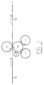
- a fuser roller 10 is shown, which is positioned so that it with a Pinch roller 12 cooperates to form paper or other medium that extends along a web of paper 18 to edit to fix an image on the paper improve or otherwise treat.
- the fuser roller 10 is positioned so that it cooperates with heating rollers 14 and is heated by them.
- the heating rollers can be driven and can drive the fuser roller 10 or can from the Fuser roller 10 are driven.
- a release agent roller 16 is in interactive contact with the fuser roller 10 to apply a thin layer of release agent (oil) to the Apply fuser roller 10.
- the release agent roller 16 is more precise below described.
- the illustrated embodiment is only too Illustration purposes and that the fuser roller 10 in a known manner from the inside could be heated. In such an embodiment, no heating rollers 14 are necessary. It can be a variety of combinations for supporting, heating and driving the Pressure roller 12, the fuser roller 10, the release agent roller 16 and optionally the Heating rollers 14 are used. The operation of such fuser rollers 10 Pressure rollers 12 and heating rollers 14 are known to the person skilled in the art.
- the fuser roller 10 includes a fuser roller body 26 which consists of a any suitable material such as Aluminum can be and that on its outer Surface is coated with a layer 20 of filled silicone rubber.
- the fuser roller 10 is covered in a known manner with filled silicone rubber.
- filled silicone rubbers can be up to 45 volume percent or more contain conductive inorganic materials such as aluminum to increase their heat capacity increase.
- these surface coatings are approximately 0.05 mm (about 0.002 inches) to about 1.3 mm (0.050 inches) thick, and preferably is Thickness between about 0.4 mm (about 0.015 inches) and 0.5 mm (about 0.02 inches).
- This Coating compared to unfilled or relatively unfilled silicone rubbers (up to 48 volume percent of an inorganic filler), which here as unfilled insulating Silicone rubbers are called, a relatively high heat capacity.
- the Fuser roller 10 further includes a layer 20 of filled silicone rubber Layer 22 of a relatively unfilled, non-conductive, insulating silicone rubber.
- This layer is typically between about 2.54 mm (about 0.1 inches) and 13 mm (about 0.50 inches) thick. This layer is preferably between 4 mm (approx. 0.150 inches) and 6 mm (about 0.250 inch) thick.
- the fuser roller 10 is used as a fuser roller for external heating shown; however, it is noted that the fuser rollers 10 are also heated from the inside could and in this case the entire silicone rubber layer one or more layers a filled silicone rubber or a similarly conductive layer. Such layers typically have a thickness between approximately 0.05 mm (approx.
- the fuser roller typically has a length of about 40 cm (about 15.5 inches). Since most copying is done on paper with approximately 28 cm (about 11 inches) wide takes place, the central section 30 of the fuser roller is the most most used section of the fuser roller. Although the entire surface is for Is available, the entire copying process is in many cases central Section 30 performed by approximately 28 cm (approximately 11 inches). Consequently, the uniform Distribution of release agent on the entire fuser roller as discussed above cause serious problems.
- a release agent is applied to the fuser roller 10 through a release agent roller 16.
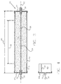
- a release agent roller is shown in Fig. 3.
- the release agent roller 16 includes one Release agent roller body 32, which contains a suitable porous material, which in the Temperature at the release agent roller is stable and penetration of the in a known manner Oil in the porous material allows when the release roller rotates.
- a suitable material is porous aluminum oxide / silicon oxide carbide.
- the Release agent roller body 32 includes a cavity 34.
- An oil line 36 conveys oil to the cavity 34 either directly or as a conduit which is essentially defined by the Cavity 34 can extend and at certain intervals along the length of the Line 36 has 32 perforations within the release agent roller body.
- Oil line 36 also includes one Pump or other means (not shown) to control the flow rate of the oil to the cavity 34 to regulate. It is desirable that the cavity 34 have a release amount of about 1 to about 20 ⁇ l per copy processed by the fuser roller.
- Typical release agents are silicone oils, which have a viscosity of 21.1 ° C (approx. 70 F) about 100 to about 100,000 centistokes, preferably from about 10,000 to have about 80,000 centistokes, and electrostatic control agents or others Additives known to those skilled in the art can help to detach the toner from the To facilitate fuser roller 10.
- the amount of oil is preferably about 1 to 3 ul per Copy.
- conduit 36 enters cavity 34 and extends through through the cavity 34.
- the release agent roller body 32 is around Release agent line 36 is rotatable and is shown in roller supports 38, which at each end are rotated.
- the release agent roller can be on both ends or only on one end be supported.
- the release agent roller 16 has an overall length 46 which is approximately that of Fuser roller 10 corresponds.
- the release roller 16 also has a central section 48 which is approximately equal to that of the fuser roller 10.
- a Oil transfer surface 42 is on the outer surface of roller 16 and layer 40 positioned and in oil transfer contact with the roller 10 and the Release agent roller body 32.
- end covers 44 are for locking attached to each end of roller 16.
- Fig. 4 is an end portion of the release roller 16 with one of the sections 40 with the shown oil-impermeable layer.
- a passage opening 50 shown as a slot is arranged in this section to allow limited amounts of oil in sections are available outside the central portion 30 of the fuser roller 10.
- the Opening shown as a slot for illustration purposes, the opening may be a And may include a plurality of openings in substantially any configuration be positioned that the desired oil flow volume and distribution is reached along the end portions of the fuser roller 10. The is preferably Total area of all openings between about 0.07 and about 3 percent, and in particular between 0.07 and 1.7 percent.
- the openings are essentially each Shape, it is desirable that they be large enough to allow oil flow enable them to be numerous enough to achieve the desired flow volume and that they are small enough to control flow and distribution to reach.
- An oil impermeable layer 40 is applied around the release agent roller body 32 the illustrated end portions before placing the oil transfer surface 42 over the entire length of the release agent roller 16 attached.
- the oil transfer surface can be out any suitable material.
- Such a material is a Aramid fiber material that under the NOMEX brand from Dupont de Nemours & Company can be obtained.
- This material is a resilient felt material that is suitable for use with the Temperatures on the fuser roller surface to ensure that the oil that Release agent roller body 32 happens to transfer to the fuser roller 10. Similar ones Oil passing through the opening 50 is applied to the surface of the fuser roller 10 transferred, but in smaller quantities. By observing the amount of release agent that is transferred to the fuser roller 10, the quantity can be adjusted. Ifshrinking, tearing, etc. a wider slit or larger can be observed or more openings are used. If swelling is observed, the Size and number of openings can be reduced. If slots as openings A single slot is used that is parallel to a longitudinal axis 52 of the Release agent roller 16 is arranged, preferably; however, it can also be a plurality such slots are used.
- the cumulative latitude also called the equivalent latitude the slots should be between 0.5 mm and 2.5 mm (approx. 0.020 - 0.100 inch) be.
- the total or equivalent width of the slot is 50 or the slots 50 approximately between 0.5 mm (about 0.020 inches) to 1.0 mm (0.040 inches) and the Slot extends or the slots extend along at least one Major portion of a length of the release layer 40.
- the slot 50 or the slots 50 can be parallel to a longitudinal axis of the release agent roller 16 be arranged and extend from the vicinity of the ends 94 to the vicinity of the ends of the central one Section 48 and along at least about 90 percent of the length of layer 40 extend.
- the slot length is preferably about 70 to 90 percent of the length of layer 40.
- the slot can also be in layer 40 in a spiral, diagonal or other configuration as long as it extends over the desired length.
- a wide variety of configurations can be used as long as the slot section available for the release of oil can release the desired amount of oil. If other openings are used it is desirable that they be dimensioned and positioned, such as It is necessary to achieve the desired flow volume and distribution.
- the oil-impermeable layer can be made of any suitable material that the used temperatures and the present pressure impermeable to the used Is oil.
- a suitable material is under the MAGNABOND brand from Crossfield Products Corporation distributed.
- the materials used for the outside of the fuser roller 10 are typically filled silicone rubbers known to the person skilled in the art.
- the surface of the Fuser roller 10 is typically heated to a temperature of about 166 ° C to 196 ° C (approx. 330 to 385 F) heated.
- the use of the oil as described above is special effective with such silicone rubbers and is useful with other oil materials absorb in a similar application.
- the release agent is typically silicone oil that has a viscosity between about 100 at 21.1 ° C (about 70 F) and has about 100,000 centistokes.
- a suitable oil is sold under the brand DC 200 by Marketed by Dow Corning, Midland, Michigan.
- a typical additive to use with such oils is sold under the trademark SILWET by Union Carbide Corporation, marketed.
- the method according to the invention thus extends the useful life of Fuser rollers. This represents a remarkable reduction in operating costs for copy and imaging equipment.
- the application can an equal amount of oil into one along the entire width of the fuser surface Guide fuser oil to the unused end portions of the fuser surface until the oil drips from end portions of the fixing portions onto the ground or in contact with the other components of the copier / duplicator what the operation impaired and can lead to the formation of a puddle under the machine.
- the presence of this fuser oil on the end sections in the case of Fixing process used elevated temperatures for the occurrence of oil vapors in the Copy / duplicate machine, which is harmful to the life of the corona charger or similar. is.
- the presence of the accumulated oil on the outer ends of the fixing surface can make oily copies or similar lead when making wider copies.
- the Use of the improved release agent roller according to the invention allows one Controlling the accumulation of excess fuser oil at the ends of the fixation surface, while at the same time providing a selected amount of fuser oil so that this stay covered with oil.
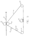
- the paper moves along a path 18.
- the paper is between the Pressure roller 12 and the counter-pressure roller 58 held by a fuser belt 54, the may include metallic or polymeric materials.
- the fuser belt 54 moves on a path between the pressure roller 12 and Counter-pressure roller 58 in rollers 52.
- the fuser belt 54 can be heated by a radiant heater 56, be heated by a heating roller 14 or by both.
- the inventive improved release roller 16 is shown in a position where it is the fuser belt oil before the fuser band comes into contact with the paper.
- fuser oil is preferably applied to the sections that are on most used for copying, i.e. in the central section of the fuser band a width of 28 cm (approx. 11 inches).
- the accumulation of fuser oil at the outer ends the fuseband is not desirable. While unique in terms of lifespan Improvements can be achieved through the filled silicone rubber on the fuser roller can, the additional improvements made by using the improvement of the release agent roller according to the invention can be achieved, both when Fuser roller system as well as implemented in the fuser belt system.
Landscapes
- Physics & Mathematics (AREA)
- General Physics & Mathematics (AREA)
- Fixing For Electrophotography (AREA)
- Coating Apparatus (AREA)
- Rolls And Other Rotary Bodies (AREA)
- Application Of Or Painting With Fluid Materials (AREA)
Abstract
Description
- Fig. 1
- eine schematische Darstellung einer Fuserwalze in Kombination mit einer Andruckwalze, Heizwalzen und einer Trennmittelwalze zur Verwendung bei der Behandlung von Papier oder einem anderem geeigneten Medium, um ein Bild auf dem Papier zu fixieren, die Qualität des Bildes zu steigern oder das Bild auf andere Weise zu verbessern;
- Fig. 2
- eine Querschnittsansicht einer bekannten Fuserwalze;
- Fig. 3
- eine Querschnittsansicht einer Trennmittelwalze;
- Fig. 4
- eine Querschnittsansicht eines Abschnitts einer Trennmittelwalze, die eine Ausführungsform der vorliegenden Erfindung zeigt; und
- Fig. 5
- eine schematische Darstellung eines Bandfusersystems.
- 10
- Fuserwalze
- 12
- Andruckwalze
- 14
- Heizwalzen
- 16
- Trennmittelwalze
- 18
- Papierbahn
- 20
- gefüllter Silikonkautschuk
- 22
- Schicht aus nichtleitendem, isolierendem gefüllten Silikonkautschuk
- 26
- Fuserwalzenkörper
- 28
- Linie
- 30
- zentraler Abschnitt
- 32
- Trennmittelwalzenkörper
- 34
- Hohlraum
- 36
- Öl-/Trennmittelleitung
- 38
- Walzenstützen
- 40
- ölundurchlässige Schicht
- 42
- Ölübertragungsfläche
- 44
- Endabdeckungen
- 46
- Gesamtlänge
- 48
- zentraler Abschnitt
- 50
- Durchlassschlitz
- 52
- Längsachse
- 52
- Walzen
- 54
- Fuserband
- 56
- Heizstrahler
- 58
- Gegendruckwalze
- 94
- Enden
Claims (16)
- Verfahren zum Verlängern der Nutzlebensdauer einer Fuserwalze (10), die Enden hat und deren Länge größer ist als ein zentraler Abschnitt (30) der Fuserwalze (10), wobei der zentrale Abschnitt (30) der Fuserwalze (10) Enden hat, und wobei sich die Endabschnitte der Fuserwalze (10) von den Enden des zentralen Abschnitts (30) der Fuserwalze (10) zu den Enden der Fuserwalze (10) erstrecken, wobei auf wenigstens einem Abschnitt der Fuserwalze (10) während des Betriebs durch Kontakt mit einer Trennmittelwalze (16) ein Trennmittel aufgetragen wird, wobei die Trennmittelwalze (16) einen porösen Trennmittelwalzenkörper (32) aufweist, der Enden hat und dessen Länge größer ist als ein zentraler Abschnitt (48) der Trennmittelwalze (16), wobei der zentrale Abschnitt (48) der Trennmittelwalze (16) Enden hat sowie eine Trennmittelversorgungsleitung (36), die in fluidischer Verbindung mit einem zentralen Hohlraum (34) im Trennmittelwalzenkörper (32) steht, eine trennmittelundurchlässige Schicht (40) über eine Länge des Trennmittelwalzenkörpers (32) zwischen den Enden der Trennmittelwalze (16) und den Enden des zentralen Abschnitts (48) der Trennmittelwalze (16) und eine Trennmittelübertragungsfläche (42) über die Außenseite der Trennmittelwalze (16) und die trennmittelundurchlässige Schicht (40), wobei wenigstens eine Öffnung (50) in der trennmittelundurchlässigen Schicht (40) in der Weise positioniert wird, dass die gesamte Öffnungsfläche ungefähr 0,7 bis 3,0 Prozent der gesamten Außenfläche der trennmittelundurchlässigen Schicht (40) entspricht und in fluidischer Verbindung mit dem Trennmittelwalzenkörper (32) und der Trennmittelübertragungsfläche (42) zwischen den Enden der Trennmittelwalze (16) und den Enden des zentralen Abschnitts (48) der Trennmittelwalze (16) steht, und wobei die Trennmittelmenge, die auf die Endabschnitte der Fuserwalze (10) übertragen wird, auf eine ausgewählte Menge eingestellt wird, umfasst.
- Verfahren nach Anspruch 1,
dadurch gekennzeichnet, dass die Fuserwalze (10) eine äußere Schicht beinhaltet, die einen gefüllten Silikonkautschuk aufweist. - Verfahren nach einem der Ansprüche 1 bis 2,
dadurch gekennzeichnet, dass die Fuserwalze (10) eine innere Schicht beinhaltet, die einen ungefüllten isolierenden Silikonkautschuk aufweist. - Verfahren nach einem der Ansprüche 1 bis 3,
dadurch gekennzeichnet, dass die äußere Schicht auf eine Temperatur von ungefähr 166 °C bis ungefähr 196°C (330 bis 385 F) erhitzt wird. - Verfahren nach einem der Ansprüche 1 bis 4,
dadurch gekennzeichnet, dass das Trennmittel ein Silikonöl ist, das eine Viskosität von ungefähr 100 bis ungefähr 100. 000 Zentistokes hat. - Verfahren nach einem der Ansprüche 1 bis 5,
dadurch gekennzeichnet, dass der Schlitz ein einziger Schlitz ist und eine Breite von ungefähr 0, 05 08 cm (0, 020 Zoll) bis 0, 10 16 cm (0, 040 Zoll) hat. - Verfahren nach einem der Ansprüche 1 bis 6,
dadurch gekennzeichnet, dass die Trennmittelmenge ausreicht, um ein Härten und Schrumpfen der äußeren Schicht oder der inneren Schicht zu verhindern, aber nicht ausreicht, um ein Schwellen der äußeren Schicht oder der inneren Schicht zu verursachen. - Verfahren nach Anspruch 7,
dadurch gekennzeichnet, dass die Menge zwischen ungefähr 1 und ungefähr 20 µl pro von der Fuserwalze (10) behandelter Kopie beträgt. - Verfahren nach einem der Ansprüche 1 bis 8,
dadurch gekennzeichnet, dass die Trennmittelmenge durch die Verwendung von Öffnungen (50) unterschiedlicher Größe eingestellt wird. - Verfahren nach einem der Ansprüche 1 bis 9,
dadurch gekennzeichnet, dass eine Mehrzahl von Schlitzen (50) verwendet wird und die Schlitze eine kumulative Breite von ungefähr 0, 05 08 cm (0, 020 Zoll) bis 0, 254 cm (0, 100 Zoll) haben. - Trennmittelwalze (16) mit einem porösen Trennmittelwalzenkörper (32), der Enden hat und dessen Länge größer ist als ein zentraler Abschnitt (48) der Trennmittelwalze (16), wobei der zentrale Abschnitt (48) der Trennmittelwalze (16) Enden hat sowie eine Trennmittelversorgungsleitung (36), die in fluidischer Verbindung mit einem zentralen Hohlraum (34) im Trennmittelwalzenkörper (32) steht, mit einer trennmittelundurchlässige Schicht (40) über eine Länge des Trennmittelwalzenkörpers (32) zwischen den Enden der Trennmittelwalze (16) und den Enden des zentralen Abschnitts (48) der Trennmittelwalze (16) und mit einer Trennmittelübertragungsfläche (42) über die Außenseite der Trennmittelwalze (16) und die trennmittelundurchlässige Schicht (40) und mit mindestens einer Öffnung (50), die in der Weise in der trennmittelundurchlässigen Schicht (40) angeordnet ist, dass die gesamte Öffnungsfläche ungefähr 0,7 bis 3,0 Prozent der gesamten Außenfläche der trennmittelundurchlässigen Schicht (40) entspricht und die Öffnung (50) in fluidischer Verbindung mit dem Trennmittelwalzenkörper (32) und der Trennmittelübertragungsfläche (42) zwischen den Enden der Trennmittelwalze (16) und den Enden des zentralen Abschnitts (48) der Trennmittelwalze (16) steht.
- Walze nach Anspruch 11,
dadurch gekennzeichnet, dass die Trennmittelversorgungsleitung (36) ein Ventil zum Einstellen des Flusses von Trennmittel in den zentralen Hohlraum (34) auf eine ausgewählte Quantität aufweist. - Walze nach einem der Ansprüche 11 bis 12,
dadurch gekennzeichnet, dass der Schlitz ein einziger Schlitz ist und eine Breite von ungefähr 0, 05 08 cm (0, 020 Zoll) bis ungefähr 0, 10 16 cm (0, 040 Zoll) hat. - Walze nach einem der Ansprüche 11 bis 13,
dadurch gekennzeichnet, dass die Trennmittelübertragungsfläche (42) Aramidfasern aufweist. - Walze nach einem der Ansprüche 11 bis 14,
dadurch gekennzeichnet, dass auf der Walze (16) Endabdeckungen (44) beinhaltet, die verschließend auf jedem Ende der Walze (16) angebracht sind. - Walze nach einem der Ansprüche 11 bis 15,
dadurch gekennzeichnet, dass die Quantität an Trennmittel, die an die Endabschnitte der Fuserwalze übertragen wird, auf eine ausgewählte Menge eingestellt wird.
Applications Claiming Priority (2)
| Application Number | Priority Date | Filing Date | Title |
|---|---|---|---|
| US09/686,705 US6317577B1 (en) | 2000-10-11 | 2000-10-11 | Method and an improved wick roller for controlling the distribution of fuser oil on a fuser surface |
| US686705 | 2000-10-11 |
Publications (2)
| Publication Number | Publication Date |
|---|---|
| EP1197814A2 true EP1197814A2 (de) | 2002-04-17 |
| EP1197814A3 EP1197814A3 (de) | 2005-10-12 |
Family
ID=24757383
Family Applications (1)
| Application Number | Title | Priority Date | Filing Date |
|---|---|---|---|
| EP01123360A Withdrawn EP1197814A3 (de) | 2000-10-11 | 2001-10-10 | Verfahren und Trennmittelwalze zum Steuern der Verteilung von Fuseröl auf einer Fixierfläche |
Country Status (5)
| Country | Link |
|---|---|
| US (1) | US6317577B1 (de) |
| EP (1) | EP1197814A3 (de) |
| JP (1) | JP2002202681A (de) |
| CA (1) | CA2358789C (de) |
| DE (1) | DE10149963A1 (de) |
Cited By (2)
| Publication number | Priority date | Publication date | Assignee | Title |
|---|---|---|---|---|
| CN103691641A (zh) * | 2014-01-03 | 2014-04-02 | 无锡市金谷塑业有限公司 | 一种薄膜的比例涂胶方法 |
| DE102014106708A1 (de) * | 2014-05-13 | 2015-11-19 | Océ Printing Systems GmbH & Co. KG | Rolle zum Aufbringen von einer Flüssigkeit auf einer Oberfläche in einem Drucker oder Kopierer |
Families Citing this family (4)
| Publication number | Priority date | Publication date | Assignee | Title |
|---|---|---|---|---|
| US6728506B2 (en) * | 2002-05-13 | 2004-04-27 | Heidelberger Druckmaschinen Ag | Wick roller for an electrophotographic machine |
| US7393312B2 (en) * | 2003-12-22 | 2008-07-01 | Xerox Corporation | Oiling roller assembly for a drum maintenance unit |
| US7215915B2 (en) * | 2004-01-30 | 2007-05-08 | Eastman Kodak Company | Method and apparatus for variable width surface treatment application to a fuser |
| JP2007193059A (ja) * | 2006-01-18 | 2007-08-02 | Seiko Epson Corp | 定着用ローラ、定着装置および画像形成装置 |
Family Cites Families (15)
| Publication number | Priority date | Publication date | Assignee | Title |
|---|---|---|---|---|
| US4359963A (en) * | 1979-04-28 | 1982-11-23 | Canon Kabushiki Kaisha | Fixing device |
| US4501483A (en) | 1983-09-02 | 1985-02-26 | Eastman Kodak Company | Fuser apparatus |
| JPS63169678A (ja) * | 1987-01-07 | 1988-07-13 | Sumitomo Electric Ind Ltd | 離型剤塗布ロ−ラ |
| US4908670A (en) * | 1988-06-20 | 1990-03-13 | Eastman Kodak Company | Wick for fixing roller |
| US5045889A (en) * | 1990-08-20 | 1991-09-03 | Eastman Kodak Company | Release liquid applying wick having a grooved feed tube |
| US5477316A (en) | 1994-05-18 | 1995-12-19 | Eastman Kodak Company | Articulatable wick assembly |
| JPH08160800A (ja) * | 1994-12-07 | 1996-06-21 | Ricoh Co Ltd | 定着装置用オイル塗布ローラ及び画像形成装置 |
| JPH08297427A (ja) * | 1995-02-22 | 1996-11-12 | Japan Gore Tex Inc | オイル塗布ロール及びそれに用いる吸油性多孔質材 |
| US5708914A (en) | 1995-09-20 | 1998-01-13 | Eastman Kodak Company | Electrostatographic apparatus having fusing process and system for improved toner offset control |
| US5732317A (en) * | 1995-11-02 | 1998-03-24 | Eastman Kodak Company | Rotating wick device |
| US5824416A (en) | 1996-03-08 | 1998-10-20 | Eastman Kodak Company | Fuser member having fluoroelastomer layer |
| US5781840A (en) | 1996-12-06 | 1998-07-14 | Eastman Kodak Company | Process for fusing a toner image to a substrate using a wicking agent |
| US5871878A (en) | 1997-03-21 | 1999-02-16 | Eastman Kodak Company | Toner offset preventing oils for zirconia ceramic and its composites rollers |
| US5805968A (en) | 1997-03-21 | 1998-09-08 | Eastman Kodak Company | Ceramic rollers |
| US6096427A (en) | 1998-07-27 | 2000-08-01 | Eastman Kodak Company | Fuser belts with adhesion promoting layer |
-
2000
- 2000-10-11 US US09/686,705 patent/US6317577B1/en not_active Expired - Fee Related
-
2001
- 2001-10-10 EP EP01123360A patent/EP1197814A3/de not_active Withdrawn
- 2001-10-10 DE DE10149963A patent/DE10149963A1/de not_active Withdrawn
- 2001-10-11 JP JP2001313416A patent/JP2002202681A/ja not_active Withdrawn
- 2001-10-11 CA CA002358789A patent/CA2358789C/en not_active Expired - Fee Related
Cited By (2)
| Publication number | Priority date | Publication date | Assignee | Title |
|---|---|---|---|---|
| CN103691641A (zh) * | 2014-01-03 | 2014-04-02 | 无锡市金谷塑业有限公司 | 一种薄膜的比例涂胶方法 |
| DE102014106708A1 (de) * | 2014-05-13 | 2015-11-19 | Océ Printing Systems GmbH & Co. KG | Rolle zum Aufbringen von einer Flüssigkeit auf einer Oberfläche in einem Drucker oder Kopierer |
Also Published As
| Publication number | Publication date |
|---|---|
| US6317577B1 (en) | 2001-11-13 |
| DE10149963A1 (de) | 2002-04-18 |
| JP2002202681A (ja) | 2002-07-19 |
| EP1197814A3 (de) | 2005-10-12 |
| CA2358789A1 (en) | 2002-04-11 |
| CA2358789C (en) | 2004-09-28 |
Similar Documents
| Publication | Publication Date | Title |
|---|---|---|
| DE3242231C2 (de) | ||
| DE69415036T2 (de) | Trennmittel zufuhrdocht für druckvorrichtung und verfahren diese herzustellen und zu verwenden | |
| DE3910459C2 (de) | ||
| DE3889935T2 (de) | Bildfixiervorrichtung und Rolle dafür. | |
| DE3016098C2 (de) | ||
| DE10332971A1 (de) | Walzeneinschmelzvorrichtung mit intelligenter Steuerung der Einschmelzelementtemperatur zum Drucken verschiedender Mediensorten | |
| DE102014204379A1 (de) | Bilderwärmungsvorrichtung | |
| DE3133021C2 (de) | ||
| DE3539377A1 (de) | Elastischer drehkoerper | |
| DE69006206T2 (de) | Verfahren und vorrichtung zum strukturieren von empfangsträgerfolien für ein tonerbild und damit hergestelltes erzeugnis. | |
| DE60308582T2 (de) | Fixiervorrichtung und damit versehenes Bilderzeugungsgerät | |
| DE3029254A1 (de) | Elektrofotografisches kopiergeraet | |
| EP0638855A1 (de) | Wärmefixiereinrichtung für ein- oder beidseitig bedruckte Aufzeichnungsträger eines Druck- oder Kopiergerätes | |
| DE2654628C2 (de) | Fixierstation für elektrostatische Kopiergeräte | |
| DE2821914C2 (de) | Schmierwalze zum Antragen einer Flüssigkeit an eine Fixierwalze für Tonerbilder | |
| DE3118606C2 (de) | Einrichtung zum Auftragen einer Flüssigkeit | |
| DE69826131T2 (de) | Wärme-Druck-Fixiereinrichtung | |
| DE69109607T2 (de) | Flüssigkeitsabgabegerät. | |
| DE10149963A1 (de) | Verfahren und verbesserte Trennmittelwalze zum Steuern der Verteilung von Fuseröl auf einer Fixierfläche | |
| DE2126239A1 (de) | Kopiergerät | |
| DE102010000549A1 (de) | Vorrichtung und Verfahren zur Entwicklung von auf einem Zwischenbildträger erzeugten Potentialbilder bei einer elektrografischen Druck- oder Kopiereinrichtung | |
| DE69516598T2 (de) | Vorrichtung zur Dosierung und zum Auftragen von Flüssigkeiten | |
| DE2257536B2 (de) | Verfahren zum Wärmeschmelzfixieren eines Tonerbildes | |
| DE102004002234B4 (de) | Einrichtung zur Regulierung der Gleiteigenschaften eines Bedruckstoffes bei einer elektrografischen Druck- oder Kopiereinrichtung | |
| DE69315332T2 (de) | Ölbehälter |
Legal Events
| Date | Code | Title | Description |
|---|---|---|---|
| PUAI | Public reference made under article 153(3) epc to a published international application that has entered the european phase |
Free format text: ORIGINAL CODE: 0009012 |
|
| AK | Designated contracting states |
Kind code of ref document: A2 Designated state(s): AT BE CH CY DE DK ES FI FR GB GR IE IT LI LU MC NL PT SE TR |
|
| AX | Request for extension of the european patent |
Free format text: AL;LT;LV;MK;RO;SI |
|
| RAP1 | Party data changed (applicant data changed or rights of an application transferred) |
Owner name: EASTMAN KODAK COMPANY |
|
| PUAL | Search report despatched |
Free format text: ORIGINAL CODE: 0009013 |
|
| AK | Designated contracting states |
Kind code of ref document: A3 Designated state(s): AT BE CH CY DE DK ES FI FR GB GR IE IT LI LU MC NL PT SE TR |
|
| AX | Request for extension of the european patent |
Extension state: AL LT LV MK RO SI |
|
| 17P | Request for examination filed |
Effective date: 20051222 |
|
| STAA | Information on the status of an ep patent application or granted ep patent |
Free format text: STATUS: THE APPLICATION HAS BEEN WITHDRAWN |
|
| 18W | Application withdrawn |
Effective date: 20060503 |