EP1197807A2 - Densitometer-Diagnosesystem für ein Bilderzeugungsgerät - Google Patents
Densitometer-Diagnosesystem für ein Bilderzeugungsgerät Download PDFInfo
- Publication number
- EP1197807A2 EP1197807A2 EP01123361A EP01123361A EP1197807A2 EP 1197807 A2 EP1197807 A2 EP 1197807A2 EP 01123361 A EP01123361 A EP 01123361A EP 01123361 A EP01123361 A EP 01123361A EP 1197807 A2 EP1197807 A2 EP 1197807A2
- Authority
- EP
- European Patent Office
- Prior art keywords
- densitometer
- diagnostic
- circuit
- output voltage
- transmitter
- Prior art date
- Legal status (The legal status is an assumption and is not a legal conclusion. Google has not performed a legal analysis and makes no representation as to the accuracy of the status listed.)
- Withdrawn
Links
Images



Classifications
-
- G—PHYSICS
- G03—PHOTOGRAPHY; CINEMATOGRAPHY; ANALOGOUS TECHNIQUES USING WAVES OTHER THAN OPTICAL WAVES; ELECTROGRAPHY; HOLOGRAPHY
- G03G—ELECTROGRAPHY; ELECTROPHOTOGRAPHY; MAGNETOGRAPHY
- G03G15/00—Apparatus for electrographic processes using a charge pattern
- G03G15/50—Machine control of apparatus for electrographic processes using a charge pattern, e.g. regulating differents parts of the machine, multimode copiers, microprocessor control
- G03G15/5033—Machine control of apparatus for electrographic processes using a charge pattern, e.g. regulating differents parts of the machine, multimode copiers, microprocessor control by measuring the photoconductor characteristics, e.g. temperature, or the characteristics of an image on the photoconductor
- G03G15/5041—Detecting a toner image, e.g. density, toner coverage, using a test patch
-
- G—PHYSICS
- G03—PHOTOGRAPHY; CINEMATOGRAPHY; ANALOGOUS TECHNIQUES USING WAVES OTHER THAN OPTICAL WAVES; ELECTROGRAPHY; HOLOGRAPHY
- G03G—ELECTROGRAPHY; ELECTROPHOTOGRAPHY; MAGNETOGRAPHY
- G03G2215/00—Apparatus for electrophotographic processes
- G03G2215/00025—Machine control, e.g. regulating different parts of the machine
- G03G2215/00029—Image density detection
- G03G2215/00033—Image density detection on recording member
- G03G2215/00037—Toner image detection
- G03G2215/00042—Optical detection
Definitions
- the present invention relates generally to imaging devices Densitometers.
- the invention relates to diagnostic systems for Densitometers used in electrophotographic imaging devices.
- Imaging devices are used to transfer images onto paper or a other material used.
- a photoconductor element becomes selective charged and optically exposed to a latent electrostatic on the surface Generate image.
- Toner is applied to the surface of the photoconductor.
- the toner is charged, which is why it adheres to the photoconductor surface in areas that latent electrostatic image.
- the toner image is on the paper or transferred another material.
- the paper is heated to the toner on the To fix paper.
- the photoconductor element is then refreshed, i.e. cleaned to remove residual toner and charge to make it available for another Prepare the imaging process.
- the densitometer is included a transmitter and a receiver on opposite sides of the Provide photoconductor element. With a densitometer using the transmission method the optical path runs from the transmitter through the photoconductor element to the receiver.
- the densitometer provides a voltage reading, which is the Corresponds to the amount of light energy that passes from the transmitter to the receiver.
- the Voltage measurement value corresponds to the density of the photoconductor element and the possibly on this toner.
- the densitometer typically works with a process field located on the surface of the Photoconductor element is located in an intermediate or edge area. When operating the Imaging device is loaded, exposed and developed to the process field to achieve the highest toner density on the process field. The densitometer determines the optical density of the toner on the process field, resulting in operational settings be made.
- an optical filter is used to determine the performance of the densitometer used.
- a portion of the photoconductor element that is devoid of toner is in the arranged optical path of the densitometer.
- a voltage reading of the Photoconductor element is measured.
- the optical filter is attached to a reading pen attached and inserted into the image forming apparatus so that the optical filter the blocked optical path of the densitometer.
- the optical filter reduces that Light energy passing photoconductor element by a predetermined amount.
- On Voltage measurement value of the photoconductor element with filter is compared with the Voltage measured value of the photoconductor element compared without a filter. If the Difference between the voltage measurements within a certain range for the filter, it is assumed that the densitometer works according to specification.
- the optical filter is difficult to use and provides subjective Voltage readings. When inserting the filter and the reading pen into the Imaging equipment must be made sure that no other parts damaged and the filter or the photoconductor element is not scratched or pressure marks be left on this. It is also important to ensure that the optical Filter is positioned correctly in front of the transmitter.
- the filter can e.g. B. at an angle to the transmitter, too close to or too far away from the transmitter, or the filter can be moved while measuring the voltage value. Additional changes can arise from the experience of that Diagnostic procedures performed by the operator.
- the Optical filters and the reading pen are quite unwieldy parts to handle.
- the filter must be protected from damage if it is not in Use is.
- densitometer diagnostic systems are needed in imaging devices that are more reliable and easier to use.
- the present invention provides a diagnostic system for a densitometer in one Imaging device ready.
- the densitometer diagnostic system has a diagnostic circuit which increases the drive current to the transmitter in the densitometer known or predictable amount decreased.
- the output voltage from the Amplifier circuit in the densitometer is proportional to the reduction in the Driving current lowered.
- the output voltage of the densitometer with Diagnostic circuit is with the output voltage of the densitometer without Diagnostic circuit compared.
- the difference between the output voltages with a voltage specification assigned to the diagnostic circuit compared. If the difference between the output voltages essentially corresponds to the voltage specification or essentially within the The same range of values, the densitometer works according to the specification.
- An imaging device with a densitometer diagnostic system can be one Photoconductor element, one or more charging stations, an exposure station, one Include toner station and a densitometer.
- the charging stations that The exposure station and the toner station are next to the photoconductor element arranged.
- the charger or chargers charge the photoconductor element electrostatically.
- the exposure station exposes optically and generates a electrostatic image on the photoconductor element.
- the toner station applies toner the photoconductor element.
- the toner has a charge to rest on stick electrostatic image.
- the densitometer can be a transmitter, a receiver, an amplifier circuit and have a diagnostic circuit.
- the transmitter and a receiver are next to it arranged the photoconductor element.
- the recipient receives mailings from Channel.
- the amplifier circuit provides a voltage supply to the transmitter and receives a current signal from the receiver.
- the amplifier circuit provides ready at least one output voltage based on the current signal.
- the Diagnostic circuit is connected to the amplifier circuit and the transmitter. The Diagnostic circuit lowers the drive current to the transmitter.
- a densitometer diagnostic system for an imaging device can include a transmitter, have a receiver, an amplifier circuit and a diagnostic circuit.
- the receiver is arranged to receive outputs from the transmitter.
- the Amplifier circuit provides a power supply to the transmitter and receives a current signal from the receiver.
- the amplifier circuit sets one up output voltage based on the current signal.
- the diagnostic circuit is with connected to the amplifier circuit and the transmitter. The diagnostic circuit lowers the control current to the transmitter.
- a procedure for diagnostic testing of a densitometer in one Imaging device with a photoconductor element has a first output voltage determined by the densitometer for the photoconductor element.
- the diagnostic circuit will connected to the densitometer.
- a second output voltage is from the Determine the densitometer for the photoconductor element. From the first and the second Output voltage, a voltage difference is determined using a voltage specification is compared.
- an alternative method for diagnostic testing of a densitometer in one Imaging device with a photoconductor element is the diagnostic circuit with the Connected densitometer.
- a first output voltage is provided by the densitometer for the photoconductor element is determined.
- the diagnostic circuit is made by the densitometer Cut.
- a second output voltage is provided by the densitometer for the Determined photoconductor element. The first and the second output voltage become A voltage difference is determined using a voltage specification is compared.
- FIG. 1 shows a block diagram of an image forming apparatus 100 having a Densitometer 122 with a diagnostic system.
- a photoconductor element 102 is effective attached to guide rollers 104.
- a motorized roller 106 moves that Photoconductor element 102 in the direction indicated by arrow A.
- a primary charging station 108, an exposure station 110, a toner station 112, a Image transfer station 114 with a material feed 116, a fusing station 118 and a cleaning station 120 are operative adjacent to the photoconductor element 102 arranged.
- the densitometer 122 has a transmitter 124 and a receiver 126 which are effectively arranged next to the photoconductor element 102.
- the Densitometer 122 also includes a diagnostic circuit (not shown).
- the photoconductor element 102 preferably has a structure composed of tape and rollers Configuration on.
- the photoconductor element 102 can be made using a drum or other suitable configuration.
- certain configurations and arrangements for the imaging device 100 other configurations and arrangements can be used , which also includes those with additional components, such as a logic and control unit (LCU).
- LCU logic and control unit
- FIG. 2 shows a block diagram of a densitometer 222 with a diagnostic system according to a first exemplary embodiment.
- the densitometer 222 includes an amplifier circuit 228, a diagnostic circuit 230, a transmitter 224 and a receiver 226.
- a densitometer according to the transmission method is shown, a densitometer according to the reflection method or another optical density meter can also be used.
- a current source 232 which may be part of the densitometer 222, provides a reference current I ref to the amplifier circuit 228.
- Amplifier circuit 228 includes a logarithmic amplifier (not shown). Other and additional amplifiers can be used. Amplifier circuit 228 preferably includes a current limiting resistor (not shown) to limit power to transmitter 224. Amplifier circuit 228 compares a current signal Ip from photodiode 226 with reference current I ref from current source 232. Amplifier circuit 228 provides an output voltage V out to the LCU ready. Another microprocessor can be used. The output voltage V out corresponds to the density of the photoconductor element 202. The LCU can display the value of the output voltage V out as received or it can convert the output voltage V out into another form or representation. The LCU can store the output voltage V out for later retrieval.
- amplifier circuit 228 provides a voltage supply Transmitter 224 through a first wire 234 and a second wire 236.
- the wires 234 and 236 have a first segment 234a and 236a, respectively, a second Segment 234b or 236b and a third segment 234c or 236c.
- a A separate (not shown) voltage source can power transmitter 224 with voltage supply.
- the transmitter 224 provides outputs such as infrared light, visible light and the same.
- the transmitter is preferably an infrared diode (IRED).
- the transmitter 224 may be a light emitting diode (LED) or other suitable emission device his.
- Transmitter 224 is preferably made of GaAlAs, although others suitable materials can be used.
- the transmitter 224 preferably has have a wavelength in the range from about 850 nm to about 950 nm. In one aspect the wavelength of the transmitter 224 is dependent on the type of Photoconductor element 202 selected.
- Receiver 226 is configured to work with transmitter 224.
- receiver 226 a photodiode.
- the receiver is 226 a silicon photodiode.
- Receiver 226 may have a (not shown) Operational amplifiers include.
- the receiver 226 provides a current signal Ip to the Amplifier circuit 228 ready.
- the transmitter 224 provides infrared light, visible light, or others Emissions ready to pass through the photoconductor element 202.
- the recipient receives these transmissions and provides a current signal Ip to amplifier circuit 228 ready.
- the current signal Ip corresponds to the energy received and therefore optical density of the photoconductor element 202.
- Diagnostic circuit 230 may be any suitable electrical circuit or a monolith circuit to reduce drive current to transmitter 224 around a known or predictable value that is marginal Error area.
- the output power of the transmitter 224 is reduced proportional to the reduction of the control current.
- the receiver 226 receives one proportional to the reduction in the output power of transmitter 224 reduced amount of energy.
- Receiver 226 is proportional to the smaller one received amount of energy lower current signal ready. Accordingly, the Output voltage from amplifier circuit 228 proportional to that of Diagnostic circuit 230 caused reduction of the drive current reduced.
- these output voltages are for the same location on the Determined photoconductor element 202.
- the photoconductor element 202 has at this point preferably no toner.
- the voltage specification is a value or range of values that the Voltage difference in the event that the densitometer specified works, i.e. if the output voltage is essentially the voltage specification corresponds to or essentially within the range of values of the same lies.
- the diagnostic circuit 230 preferably reduces the drive current in range from about 35% to 65%. In one aspect, the diagnostic circuit reduces 230 the output power of the transmitter 224 by about 50%.
- the diagnostic circuit 230 in this exemplary embodiment comprises a second one Current limiting resistor 238, a second segment 234b of the first wire 234 and a second segment 236b of the second wire 236.
- the second Current limiting resistor 238 is preferably a single resistor, but can also consist of several resistors or any suitable one Current limiting circuit.
- the second segment 236b is a Jumper wire to bridge the "gap" between the first segment 236a and the third segment 236c of the second wire 236.
- the second current limiting resistor 238 has a resistance in the range of about 100 ⁇ to about 200 ⁇ and works in a range from 0.25 W to about 2 W. In In one aspect, these values are for the second current limiting resistor 238 about 150 ⁇ and about 0.5 W.
- the second current limiting resistor 238 differs from the first Current limiting resistor in amplifier circuit 228.
- the first Current limiting resistor keeps the current level below the current limit of the Transmitter.
- the second current limiting resistor 238 in one aspect lowers the Current level to the transmitter drops below the current limit to be effective "Electrical equivalent" of a toner field, an optical filter, and the like To provide diagnostic systems.
- a variable resistor can be configured to "act" as the first and second current limiting resistors. However, this variable resistance must have a suitable accuracy in order for it to be the correct current drops are achieved.
- the diagnostic circuit 230 can (not shown) plug connections to Connecting the second segments 234b and 236b to the first segments 234a and 236a and for connecting the second segments 234b and 236b to the third Have segments 234c and 236c.
- the wires 234 and 236 can be part of the same Cable.
- a single socket (not shown) for the second segments 234b and 236b can be used with a single connector (not shown) for the first segments 234a and 236a.
- another (not shown) single plug for the second segments 234b and 236b with a further (not shown) single socket for the third segments 234c and 236c get connected.
- the diagnostic circuit 330 includes a second current limiting resistor 338, second wire segments 334b and 336b, a plug 340, a socket 346 and a sleeve 354.
- the diagnostic circuit 330 may be provided with an identification label (ID) 356.
- the Plug 340 is connected to a further (not shown) socket with third (not shown) connected wire segments.
- the socket 346 with a further (not shown) plug on the first (not shown) Wire segments connected.
- the sleeve 354 is preferably made of shrink plastic, However, can be made of any other material that is used to dissipate heat and Protection of the diagnostic circuit 330 is suitable.
- the connectors 340 and 346 can be any connections that are suitable for connecting the diagnostic circuit 330 to a densitometer.
- the Plug 340 and socket 346 can be reversed.
- the diagnostic circuit 330 two plugs and two sockets instead of one plug and one Have socket.
- an adapter (not shown) may be required be to connect the first and third wire segments when the diagnostic circuit is not in use.
- connector 340 and the Socket 346 is connected to both second wire segments 334b and 336b, respectively.
- each of the second wire segments 334b and 336b can have its own Be provided socket and its own plug.
- the diagnostic circuit 230 is preferably derived from the densitometer 222 removed if no diagnostic check is performed.
- the first segments 234a and 236a are separated from the third segments 234c and 236c.
- single or multiple sockets and plugs can be used.
- One or more adapters (not shown) can be used, if only Plugs or only sockets can be used to connect the wire segments.
- the diagnostic circuit 230 is connected to the densitometer 222.
- the first segments 234a and 236a are connected to the second segments 234b and 236b, respectively.
- the third segments 234c and 236c are connected to the second segments 234b and 236b, respectively. If the exemplary embodiment from FIG.
- a second voltage output value V out2 of the photoconductor element 202 is determined and then recorded or stored. Diagnostic circuit 230 lowers the current level to transmitter 224 to effectively generate an "electrical equivalent" of the optical filter, toner array, and the like diagnostic systems.
- the first voltage output value V out1 is compared with the second voltage output value V out2 .
- the first voltage output value V out1 is preferably subtracted from the second voltage output value V out2 in order to determine a voltage difference value V diff .
- This calculation can be done by the user. Alternatively, this calculation can be carried out by the LCU and the result can be displayed and saved.
- the voltage difference value V diff is compared to a voltage specification which indicates whether the components of the densitometer are functional.
- the voltage specification can be a specific value or a range of values and depends on the densitometer and the diagnostic circuit used.
- Diagnostic circuit 230 is disconnected from densitometer 222.
- the first segments 234a and 236a are separated from the second segments 234b and 236b, respectively.
- the third segments 234c and 236c are separated from the second segments 234b and 236b, respectively. If the exemplary embodiment in FIG. 3 or an exemplary embodiment of a similar type is used, the corresponding sockets and plugs are separated from one another.
- the first segments 234a and 236a are again connected to the third segments 234c and 236c.
- the first voltage output value V out1 can be measured after the diagnostic circuit has been disconnected from the densitometer.
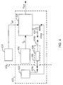
- FIG. 4 shows a block diagram of a densitometer 422 with a densitometer diagnostic system according to a second embodiment.
- the densitometer 422 is substantially the same as that in the first embodiment and in FIG. 2 to Fig. 3 described densitometers.
- the diagnostic circuit 430 includes a second current limiting resistor 438 and a second segment 434b of the first wire 434.
- the second wire 436 is not divided into segments, but rather, amplifier circuit 428 connects directly to transmitter 424.
- the second current limiting resistor 438 is preferably an Single resistor, but can also consist of several resistors or one any suitable current limiting circuit.
- the first segment 434a and the third segment of 434b is of sufficient length for connection, when the diagnostic circuit 430 is removed from the densitometer 422.
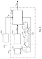
- the densitometer 522 corresponds essentially to those in the first and in the second exemplary embodiment and in 2 to 4 described densitometers.
- the diagnostic circuit 530 can not removed, but remains in the densitometer even if none Diagnostic check is made.
- the second wire 536 is not in segments but connects amplifier circuit 528 directly to transmitter 524.
- the diagnostic circuit 530 includes a current limiting circuit 538, one Switch S, a connecting wire 556, a first bypass wire 558 and one second bypass wire 560.
- the current limiting circuit 438 can be a single resistor or it can have multiple resistors.
- a wire 554 of the amplifier circuit connects amplifier circuit 528 to switch S which is between Switch pin position 1 and switch pin position 2 works.
- the connecting wire 556 connects the switch pin 1 to the transmitter wire 562 for connection to the transmitter 524.
- the first bypass wire 558 connects the switch pin 2 to the Current limiting circuit 538.
- the second bypass wire 560 connects the Current limiting circuit 538 with transmitter wire 562.
- switch S is in switch pin position 1.
- the connecting wire 556 effectively bypasses current limiting circuit 538.
- switch S is in switch pin position 2.
- Current limiting circuit 538 is activated to reduce the current and consequently the output voltage V out as described in the first and in the second embodiment.
- the current limiting circuit 538 preferably reduces the output power of the transmitter 524 in a range from approximately 35% to 65%. In one aspect, current limiting circuit 538 reduces the output power of transmitter 524 by approximately 50%.
- the switch S can be any suitable switching device that can be operated manually, but is preferably controlled electronically by the LCU.
- a densitometer determines a first voltage output value V out1 of the photoconductor element .
- a portion of the photoconductor element, which preferably has no toner, is arranged in the optical path of the transmitter and the receiver.
- the densitometer provides the first voltage output value V out1 .
- the first voltage output value V out1 is recorded or stored in step 666.
- the diagnostic circuit is connected to the densitometer in step 668.
- the diagnostic circuit can have a plug-in structure like that described in the first, in the second, and in a similar manner in exemplary embodiments.
- the diagnostic circuit can be part of or connected to the densitometer, as described in the third or an embodiment of a similar type.
- the densitometer determines a second voltage output value V out2 of the photoconductor element .
- the second voltage output value V out2 is stored or recorded in step 672.
- a voltage difference value V diff is determined in step 674.
- the first voltage output value V out1 is compared with the second voltage output value V out2 .
- the first voltage output value V out1 is preferably subtracted from the second voltage output value V out2 in order to determine the voltage difference value V diff .
- the voltage difference value V diff is compared in step 676 with a voltage specification V spec .
- the components of the densitometer are functional when the voltage difference value V diff corresponds to the value of the voltage specification V spec or is within a range of values thereof.
- the voltage specification V spec depends on the densitometer and the diagnostic circuit used.
- the diagnostic circuit is disconnected from the densitometer in step 678.
- the diagnosis circuit can be separated in step 670 after determining the second voltage output value V out2 .
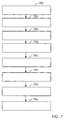
- the diagnostic circuit is connected to the densitometer in step 782.
- the diagnostic circuit can have a plug-in structure, as described in the first and in the second exemplary embodiment or in exemplary embodiments of a similar type.
- the diagnostic circuit can be part of or connected to the densitometer, as described in the third or an embodiment of a similar type.
- a section of the photoconductor element, which preferably has no toner, is arranged in the optical path of the transmitter and the receiver.
- the densitometer determines a first voltage output value V out1 of the photoconductor element .
- the first voltage output value V out1 is stored or recorded in step 786.
- the diagnostic circuit is disconnected from the densitometer in step 788.
- the densitometer determines a second voltage output value V out2 of the photoconductor element .
- the second voltage output value V out2 is recorded or stored in step 792.
- a voltage difference value V diff is determined in step 794.
- the first voltage output value V out1 is compared with the second voltage output value V out2 .
- the second voltage output value V out2 is preferably subtracted from the first voltage output value V out1 in order to determine the voltage difference value V diff .
- the voltage difference value V diff is compared in step 796 with a voltage specification V spec .
- the components of the densitometer are functional if the voltage difference value V diff corresponds to the voltage specification V spec or lies within a range of values thereof.
- the voltage specification V spec depends on the densitometer and the diagnostic circuit used.
Landscapes
- Engineering & Computer Science (AREA)
- Microelectronics & Electronic Packaging (AREA)
- Physics & Mathematics (AREA)
- General Physics & Mathematics (AREA)
- Control Or Security For Electrophotography (AREA)
Abstract
Description
- Fig. 1
- ein Blockdiagramm eines Bilderzeugungsgeräts mit einem Densitometer-Diagnosesystem;
- Fig. 2
- ein Blockdiagramm eines Densitometers mit einem Diagnosesystem gemäß eines ersten Ausführungsbeispiels;
- Fig. 3A
- eine Längsseite der Diagnose-Schaltung;
- Fig. 3B
- eine erste Endansicht der Diagnose-Schaltung;
- Fig. 3C
- eine zweite Endansicht der Diagnose-Schaltung;
- Fig. 4
- ein Blockdiagramm eines Densitometers mit einem Diagnosesystem gemäß einem zweiten Ausführungsbeispiel;
- Fig. 5
- ein Blockdiagramm eines Densitometers mit einem Diagnosesystem gemäß einem dritten Ausführungsbeispiel;
- Fig. 6
- ein Ablaufdiagramm eines Verfahrens zur Diagnoseprüfung eines Densitometers in einem Bilderzeugungsgerät;
- Fig. 7
- ein Ablaufdiagramm eines alternativen Verfahrens zur Diagnoseprüfung eines Densitometers in einem Bilderzeugungsgerät.
- 100
- Bilderzeugungsgerät
- 102
- Fotoleiterelement
- 104
- Führungswalzen
- 106
- motorgetriebene Walze
- 108
- Ladestation
- 110
- Belichtungsstation
- 112
- Tonerstation
- 114
- Bildübertragungsstation
- 116
- Materialeinzug
- 118
- Fuserstation
- 120
- Reinigungsstation
- 122
- Densitometer
- 124
- Sender
- 126
- Empfänger
- A
- Pfeil
- 202
- Fotoleiterelement
- 222
- Densitometer
- 224
- Sender
- 226
- Empfänger
- 228
- Verstärker-Schaltung
- 230
- Diagnose-Schaltung
- 232
- Stromquelle
- 234
- erster Draht
- 236
- zweiter Draht
- 234a, 236a
- erste Segmente
- 234b, 236b
- zweite Segmente
- 234c, 236c
- dritte Segmente
- 238
- Strombegrenzungswiderstand
- 330
- Diagnose-Schaltung
- 334b, 336b
- zweite Segmente
- 338
- Strombegrenzungswiderstand
- 340
- Stecker
- 346
- Buchse
- 354
- Hülse
- 422
- Densitometer
- 424
- Sender
- 428
- Verstärker-Schaltung
- 430
- Diagnose-Schaltung
- 434
- erster Draht
- 434a
- erstes Segment
- 434b
- zweites Segment
- 436
- zweiter Draht
- 438
- Strombegrenzungswiderstand
- 522
- Densitometer
- 524
- Sender
- 528
- Verstärker-Schaltung
- 530
- Diagnose-Schaltung
- 536
- zweiter Draht
- 538
- Strombegrenzungsschaltung
- 556
- Verbindungsdraht
- 558
- erster Umgehungsdraht
- 560
- zweiter Umgehungsdraht
- 562
- Senderdraht
- S
- Schalter
- 664, 666-678
- Verfahrensschritte
- 782, 784-796
- Verfahrensschritte
Claims (39)
- Bilderzeugungsgerät mit einem Densitometer-Diagnosesystem, welches die folgenden Merkmale umfasst:ein Fotoleiterelement (102, 202);wenigstens eine zum elektrostatischen Laden des Fotoleiterelements (102, 202) wirksam angeordnete Ladestation (108);eine zum optischen Belichten und Erzeugen eines elektrostatischen Bildes auf dem Fotoleiterelement (102, 202) wirksam angeordnete Belichtungsstation (110);eine zum Aufbringen von Toner auf das Fotoleiterelement (102, 202) wirksam angeordnete Tonerstation (112), wobei der Toner eine Ladung aufweist, um auf dem elektrostatischen Bild anzuhaften, undein Densitometer (122, 222, 422, 522) miteinem Sender (124, 224, 424, 524) und einem Empfänger (126, 226, 426, 526), welche wirksam neben dem Fotoleiterelement (102, 202) angeordnet sind, wobei der Empfänger (126, 226, 426, 526) Aussendungen des Senders (124, 224, 424, 524) empfängt,einer Verstärker-Schaltung (228, 428, 528), welche zum Bereitstellen einer Spannungsversorgung zum Sender (124, 224, 424, 524) und zum Empfangen eines Stromsignals vom Empfänger (126, 226, 426, 526) elektrisch angeschlossen ist, wobei die Verstärker-Schaltung (228, 428, 528) wenigstens eine auf dem Stromsignal basierende Ausgabespannung liefert, undeiner zum Verbinden der Verstärker-Schaltung (228, 428, 528) und des Senders (124, 224, 424, 524) wirksam angeordneten Diagnose-Schaltung (230, 430, 530), wobei die Diagnose-Schaltung (230, 430, 530) zum Absenken des Ansteuerungsstroms zum Sender (124, 224, 424, 524) dient.
- Bilderzeugungsgerät nach Anspruch 1,
welches ferner eine Stromquelle (232) zum Bereitstellen eines Referenzstroms an die Verstärker-Schaltung (228, 428, 528) umfasst. - Bilderzeugungsgerät nach Anspruch 2,
dadurch gekennzeichnet, dass die Verstärker-Schaltung (228, 428, 528) auf der Grundlage eines Vergleichs zwischen dem Stromsignal und dem Referenzstrom die wenigstens eine Ausgabespannung bestimmt. - Bilderzeugungsgerät nach Anspruch 1,
welches ferner eine Logik- und Steuerungseinheit umfasst, wobei die Verstärker-Schaltung (228, 428, 528) die wenigstens eine Ausgabespannung an die Logik- und Steuerungseinheit bereitstellt. - Bilderzeugungsgerät nach Anspruch 4,
dadurch gekennzeichnet, dass die wenigstens eine Ausgabespannung eine erste Ausgabespannung und eine zweite Ausgabespannung umfasst, wobei die erste Ausgabespannung bereitgestellt wird, wenn die Diagnose-Schaltung (230, 430, 530) angeschlossen ist, und die zweite Ausgabespannung bereitgestellt wird, wenn die Diagnose-Schaltung (230, 430, 530) nicht angeschlossen ist. - Bilderzeugungsgerät nach Anspruch 5,
dadurch gekennzeichnet, dass die Logik- und Steuerungseinheit einen Vergleich der ersten und der zweiten Ausgabespannung durchführt, um eine Spannungsdifferenz zu ermitteln. - Bilderzeugungsgerät nach Anspruch 6,
dadurch gekennzeichnet, dass die Logik- und Steuerungseinheit die Spannungsdifferenz mit einer Spannungs-Spezifikation vergleicht. - Bilderzeugungsgerät nach Anspruch 1,
dadurch gekennzeichnet, dass die Diagnose-Schaltung (230, 430, 530) den Ansteuerungsstrom in einem Bereich von etwa 35 % bis etwa 65 % absenkt. - Bilderzeugungsgerät nach Anspruch 1,
dadurch gekennzeichnet, dass die Diagnose-Schaltung (230, 430, 530) den Ansteuerungsstrom um etwa 50 % absenkt. - Diagnosesystem für ein Densitometer nach Anspruch 1,
dadurch gekennzeichnet, dass die Diagnose-Schaltung (230, 430, 530) eine Strombegrenzungsschaltung umfasst. - Bilderzeugungsgerät nach Anspruch 1,
dadurch gekennzeichnet, dass die Diagnose-Schaltung (230, 430, 530) einen Strombegrenzungswiderstand (238, 338, 438, 538) umfasst. - Bilderzeugungsgerät nach Anspruch 11,
dadurch gekennzeichnet, dass der Strombegrenzungswiderstand (238, 338, 438, 538) Widerstand in einem Bereich von etwa 100 Ω bis etwa 200Ω bereitstellt und in einem Bereich von etwa 0,25 W bis etwa 2W arbeitet. - Bilderzeugungsgerät nach Anspruch 11,
dadurch gekennzeichnet, dass der Strombegrenzungswiderstand (238, 338, 438, 538) einen Widerstand von etwa 150 Ω bereitstellt und bei etwa 1W arbeitet. - Bilderzeugungsgerät nach Anspruch 1,
dadurch gekennzeichnet, dass die Verstärker-Schaltung (228, 428, 528) einen ersten Strombegrenzungswiderstand (238, 338, 438, 538) umfasst, und die Diagnose-Schaltung (230, 430, 530) einen zweiten Strombegrenzungswiderstand (238, 338, 438, 538) umfasst. - Bilderzeugungsgerät nach Anspruch 1,
welches ferner einen Schalter (S) zum Verbinden und Trennen der Diagnose-Schaltung (230, 430, 530) umfasst. - Bilderzeugungsgerät nach Anspruch 1,
dadurch gekennzeichnet, dass die Diagnose-Schaltung (230, 430, 530) aus dem Densitometer (122, 222, 422, 522) entfernt werden kann. - Densitometer-Diagnosesystem für ein Bilderzeugungsgerät, welches die folgenden Merkmale umfasst:einen Sender (124, 224, 424, 524);einen Empfänger (126, 226, 426, 526), der zum Empfangen von Aussendungen des Sender (124, 224, 424, 524)s wirksam angeordnet ist;eine Verstärker-Schaltung (228, 428, 528), die zum Bereitstellen einer Spannungsversorgung zum Sender (124, 224, 424, 524) und zum Empfangen eines Stromsignals vom Empfänger (126, 226, 426, 526) elektrisch verbunden ist, wobei die Verstärker-Schaltung (228, 428, 528) zum Bereitstellen wenigstens einer auf dem Stromsignal basierenden Ausgabespannung dient; undeine Diagnose-Schaltung (230, 430, 530), die zum Verbinden der Verstärker-Schaltung (228, 428, 528) und des Senders (124, 224, 424, 524) wirksam angeordnet ist, wobei die Diagnose-Schaltung (230, 430, 530) zum Absenken des Ansteuerungsstroms zum Sender (124, 224, 424, 524) dient.
- Densitometer-Diagnosesystem nach Anspruch 17,
welches weiterhin eine Stromquelle (232) zum Bereitstellen eines Referenzstroms an die Verstärker-Schaltung (228, 428, 528) umfasst. - Densitometer-Diagnosesystem nach Anspruch 18,
dadurch gekennzeichnet, dass die Verstärker-Schaltung (228, 428, 528) die wenigstens eine Ausgabespannung auf der Grundlage eines Vergleichs des Stromsignals und des Referenzstroms bestimmt. - Densitometer-Diagnosesystem nach Anspruch 17,
dadurch gekennzeichnet, dass die Verstärker-Schaltung (228, 428, 528) eine erste Ausgabespannung bereitstellt, wenn die Diagnose-Schaltung (230, 430, 530) angeschlossen ist, und die Verstärker-Schaltung (228, 428, 528) eine zweite Ausgabespannung bereitstellt, wenn die Diagnose-Schaltung (230, 430, 530) nicht angeschlossen ist. - Densitometer-Diagnosesystem nach Anspruch 17,
dadurch gekennzeichnet, dass die Diagnose-Schaltung (230, 430, 530) eine Strombegrenzungsschaltung umfasst. - Densitometer-Diagnosesystem nach Anspruch 17,
dadurch gekennzeichnet, dass die Diagnose-Schaltung (230, 430, 530) einen Strombegrenzungswiderstand (238, 338, 438, 538) umfasst. - Densitometer-Diagnosesystem nach Anspruch 22,
dadurch gekennzeichnet, dass der Strombegrenzungswiderstand (238, 338, 438, 538) Widerstand in einem Bereich von etwa 100 Ω bis etwa 200Ω bereitstellt und in einem Bereich von etwa 0,25 W bis etwa 2W arbeitet. - Densitometer-Diagnosesystem nach Anspruch 19,
dadurch gekennzeichnet, dass der Strombegrenzungswiderstand (238, 338, 438, 538) einen Widerstand von etwa 150 Ω bereitstellt und bei etwa 1W arbeitet. - Densitometer-Diagnosesystem nach Anspruch 17,
dadurch gekennzeichnet, dass die Verstärker-Schaltung (228, 428, 528) einen ersten Strombegrenzungswiderstand (238, 338, 438, 538) umfasst, und die Diagnose-Schaltung (230, 430, 530) einen zweiten Strombegrenzungswiderstand (238, 338, 438, 538) umfasst. - Densitometer-Diagnosesystem nach Anspruch 17,
welches weiterhin einen Schalter (S) zum Verbinden und Trennen der Diagnose-Schaltung (230, 430, 530) umfasst. - Densitometer-Diagnosesystem nach Anspruch 17,
dadurch gekennzeichnet, dass die Diagnose-Schaltung (230, 430, 530) aus dem Densitometer (122, 222, 422, 522) entfernt werden kann. - Densitometer-Diagnosesystem nach Anspruch 17,
dadurch gekennzeichnet, dass der Sender (124, 224, 424, 524) entweder eine Leuchtdiode (LED) oder eine Infrarotdiode (IRED) ist. - Verfahren zur Diagnoseprüfung eines Densitometers in einem Bilderzeugungsgerät mit einem Fotoleiterelement (102, 202), welches die folgenden Schritte umfasst:(a) Erhalten einer ersten Ausgabespannung vom Densitometer (122, 222, 422, 522) für das Fotoleiterelement (102, 202);(b) Verbinden der Diagnose-Schaltung (230, 430, 530) mit dem Densitometer (122, 222, 422, 522);(c) Erhalten einer zweiten Ausgabespannung vom Densitometer (122, 222, 422, 522) für das Fotoleiterelement (102, 202);(d) Ermitteln einer Spannungsdifferenz aus der ersten und der zweiten Ausgabespannung, und(e) Vergleichen der Spannungsdifferenz mit einer Spannungs-Spezifikation.
- Verfahren zur Diagnoseprüfung nach Anspruch 29,
dadurch gekennzeichnet, dass wenigstens einer der Schritte (a) und (c) ferner den Unterschritt eines Speicherns von einer der ersten oder zweiten Ausgabespannung umfasst. - Verfahren zur Diagnoseprüfung nach Anspruch 29,
welches ferner den Schritt eines Trennens der Diagnose-Schaltung (230, 430, 530) nach Schritt (c) umfasst. - Verfahren zur Diagnoseprüfung nach Anspruch 29,
dadurch gekennzeichnet, dass Schritt (d) ferner den Unterschritt eines Subtrahierens der ersten Ausgabespannung von der zweiten Ausgabespannung zum Bestimmen der Spannungsdifferenz umfasst. - Verfahren zur Diagnoseprüfung nach Anspruch 29,
dadurch gekennzeichnet, dass die Diagnose-Schaltung (230, 430, 530) einen Strombegrenzungswiderstand (238, 338, 438, 538) umfasst. - Verfahren zur Diagnoseprüfung nach Anspruch 29,
dadurch gekennzeichnet, dass die Diagnose-Schaltung (230, 430, 530) aus dem Densitometer (122, 222, 422, 522) entfernt werden kann. - Verfahren zur Diagnoseprüfung eines Densitometers in einem Bilderzeugungsgerät mit einem Fotoleiterelement (102, 202), welches die folgenden Schritte umfasst:(a) Verbinden der Diagnose-Schaltung (230, 430, 530) mit dem Densitometer (122, 222, 422, 522);(b) Erhalten einer ersten Ausgabespannung vom Densitometer (122, 222, 422, 522) für das Fotoleiterelement (102, 202);(c) Trennen der Diagnose-Schaltung (230, 430, 530) vom Densitometer (122, 222, 422, 522);(d) Erhalten einer zweiten Ausgabespannung vom Densitometer (122, 222, 422, 522) für das Fotoleiterelement (102, 202);(e) Bestimmen einer Spannungsdifferenz aus der ersten und der zweiten Ausgabespannung, und(f) Vergleichen der Spannungsdifferenz mit einer Spannungs-Spezifikation.
- Verfahren zur Diagnoseprüfung nach Anspruch 35,
dadurch gekennzeichnet, dass wenigstens einer der Schritte (b) und (d) weiterhin den Unterschritt eines Speichern von einer der ersten oder zweiten Ausgangspannung umfasst. - Verfahren zur Diagnoseprüfung nach Anspruch 35,
dadurch gekennzeichnet, dass Schritt (e) weiterhin den Unterschritt eines Subtrahierens der zweiten Ausgabespannung von der ersten Ausgabespannung zum Bestimmen der Spannungsdifferenz umfasst. - Verfahren zur Diagnoseprüfung nach Anspruch 35,
dadurch gekennzeichnet, dass die Diagnose-Schaltung (230, 430, 530) einen Strombegrenzungswiderstand (238, 338, 438, 538) umfasst. - Verfahren zur Diagnoseprüfung nach Anspruch 35,
dadurch gekennzeichnet, dass die Diagnose-Schaltung (230, 430, 530) aus dem Densitometer (122, 222, 422, 522) entfernt werden kann.
Applications Claiming Priority (2)
| Application Number | Priority Date | Filing Date | Title |
|---|---|---|---|
| US687647 | 2000-10-13 | ||
| US09/687,647 US6385411B1 (en) | 2000-10-13 | 2000-10-13 | Densitometer diagnostic system for an image-forming machine |
Publications (2)
| Publication Number | Publication Date |
|---|---|
| EP1197807A2 true EP1197807A2 (de) | 2002-04-17 |
| EP1197807A3 EP1197807A3 (de) | 2005-10-12 |
Family
ID=24761239
Family Applications (1)
| Application Number | Title | Priority Date | Filing Date |
|---|---|---|---|
| EP01123361A Withdrawn EP1197807A3 (de) | 2000-10-13 | 2001-10-10 | Densitometer-Diagnosesystem für ein Bilderzeugungsgerät |
Country Status (5)
| Country | Link |
|---|---|
| US (1) | US6385411B1 (de) |
| EP (1) | EP1197807A3 (de) |
| JP (1) | JP4027067B2 (de) |
| CA (1) | CA2358616C (de) |
| DE (1) | DE10149966A1 (de) |
Families Citing this family (3)
| Publication number | Priority date | Publication date | Assignee | Title |
|---|---|---|---|---|
| US6567171B1 (en) | 2000-04-03 | 2003-05-20 | Rushing Allen J | Digital densitometer with controlled light emitter |
| US6813128B2 (en) * | 2001-05-25 | 2004-11-02 | Nexpress Solutions Llc | High voltage bias feedback for diagnostic purposes |
| US8139981B2 (en) * | 2008-01-22 | 2012-03-20 | Eastman Kodak Company | Spring-loaded web cleaning apparatus for electrographic printer |
Family Cites Families (8)
| Publication number | Priority date | Publication date | Assignee | Title |
|---|---|---|---|---|
| US4553033A (en) * | 1983-08-24 | 1985-11-12 | Xerox Corporation | Infrared reflectance densitometer |
| US5119132A (en) * | 1990-10-24 | 1992-06-02 | Xerox Corporation | Densitometer and circuitry with improved measuring capabilities of marking particle density on a photoreceptor |
| US5117119A (en) * | 1991-03-13 | 1992-05-26 | Minnesota Mining And Manufacturing Company | Auto-ranging film densitometer |
| US5678132A (en) * | 1994-04-26 | 1997-10-14 | Canon Kabushiki Kaisha | Image density detection adjustment device |
| US5574544A (en) * | 1994-08-29 | 1996-11-12 | Konica Corporation | Image forming apparatus having image density gradation correction means |
| US5773827A (en) * | 1996-12-16 | 1998-06-30 | Xerox Corporation | Xerographic infrared reflectance densitometer (IRD) sensor |
| US5903800A (en) | 1998-06-04 | 1999-05-11 | Eastman Kodak Company | Electrostatographic reproduction apparatus and method with improved densitometer |
| US6229972B1 (en) * | 2000-04-03 | 2001-05-08 | Allen J. Rushing | Digital densitometer with calibration and statistics |
-
2000
- 2000-10-13 US US09/687,647 patent/US6385411B1/en not_active Expired - Fee Related
-
2001
- 2001-10-10 JP JP2001312635A patent/JP4027067B2/ja not_active Expired - Fee Related
- 2001-10-10 EP EP01123361A patent/EP1197807A3/de not_active Withdrawn
- 2001-10-10 DE DE10149966A patent/DE10149966A1/de not_active Withdrawn
- 2001-10-11 CA CA002358616A patent/CA2358616C/en not_active Expired - Fee Related
Also Published As
| Publication number | Publication date |
|---|---|
| CA2358616C (en) | 2004-07-27 |
| CA2358616A1 (en) | 2002-04-13 |
| EP1197807A3 (de) | 2005-10-12 |
| US6385411B1 (en) | 2002-05-07 |
| JP2002132096A (ja) | 2002-05-09 |
| DE10149966A1 (de) | 2002-04-18 |
| JP4027067B2 (ja) | 2007-12-26 |
Similar Documents
| Publication | Publication Date | Title |
|---|---|---|
| DE2916945C2 (de) | Vorrichtung zur Einstellung eines elektrophotographischen Kopiergerätes | |
| DE3912202C2 (de) | Elektrografisches Aufzeichnungsgerät | |
| DE2928402C2 (de) | Einrichtung zur Einstellung der Betriebsparameter eines elektrophotographischen Kopiergerätes | |
| DE2915052C2 (de) | Verfahren zur Steuerung und Vorrichtung zur optischen Überwachung der Tonerbilddichte in einem elektrophotographischen Kopiergerät | |
| DE3851806T2 (de) | Bilderzeugungsgerät mit einer Vorrichtung zur Messung der Konzentration eines Entwicklungsmittels. | |
| DE4228560C2 (de) | Bilderzeugungsgerät | |
| DE19608507B4 (de) | Entwicklungseinrichtung für eine Bilderzeugungsvorrichtung | |
| DE69817454T2 (de) | Bilderzeugungsgerät | |
| DE3211982A1 (de) | Reproduktionseinheit und bilderzeugungsgeraet mit derselben | |
| DE69730920T2 (de) | Bilderzeugungsgerät und dazu montierbare Prozesskassette | |
| DE2729678B2 (de) | Verfahren und Vorrichtung zur Kontrolle des Gebrauchszustandes eines dispergierte Tonerteilchen enthaltenden elektrophotographischen Flüssigentwicklers | |
| DE68918313T2 (de) | Elektrostatisches Aufnahmegerät. | |
| DE102017102023A1 (de) | Bilderzeugungsvorrichtung und Steuerverfahren für eine Bilderzeugungsvorrichtung | |
| DE3929562A1 (de) | Pruefungseinrichtung fuer endoskopausruestungen | |
| DE3840712A1 (de) | Vorrichtung zum entwickeln eines auf einem photorezeptor erzeugten latentbilds | |
| DE60033594T2 (de) | Bilderzeugungsgerät | |
| EP1178362A2 (de) | Bilderzeugungsvorrichtung mit Online-Bewertung der Bildqualität und zugehörigem Verfahren | |
| DE69107377T2 (de) | Bildaufnahmegerät. | |
| DE3337881C2 (de) | Vorrichtung zur Feststellung von Störungen einer Aufladeeinheit | |
| DE2325962A1 (de) | Elektrofotografisches kopierverfahren | |
| DE202007010785U1 (de) | Vorrichtung zum Verspleißen von Lichtwellenleitern | |
| DE4035733C2 (de) | Bildübertragungseinrichtung für einen elektrofotografischen Drucker | |
| DE10149966A1 (de) | Densitometer-Diagnosesystem für ein Bilderzeugungsgerät | |
| DE69922614T2 (de) | Vorrichtung und Verfahren zur Messung der Entwicklerkontamination in einem Drucker | |
| DE10136748A1 (de) | Bilderzeugungsvorrichtung und zugehöriges Verfahren mit Laderreinigeraktivierung nach Lichtbogenfehler |
Legal Events
| Date | Code | Title | Description |
|---|---|---|---|
| PUAI | Public reference made under article 153(3) epc to a published international application that has entered the european phase |
Free format text: ORIGINAL CODE: 0009012 |
|
| AK | Designated contracting states |
Kind code of ref document: A2 Designated state(s): AT BE CH CY DE DK ES FI FR GB GR IE IT LI LU MC NL PT SE TR |
|
| AX | Request for extension of the european patent |
Free format text: AL;LT;LV;MK;RO;SI |
|
| RAP1 | Party data changed (applicant data changed or rights of an application transferred) |
Owner name: EASTMAN KODAK COMPANY |
|
| PUAL | Search report despatched |
Free format text: ORIGINAL CODE: 0009013 |
|
| AK | Designated contracting states |
Kind code of ref document: A3 Designated state(s): AT BE CH CY DE DK ES FI FR GB GR IE IT LI LU MC NL PT SE TR |
|
| AX | Request for extension of the european patent |
Extension state: AL LT LV MK RO SI |
|
| 17P | Request for examination filed |
Effective date: 20060323 |
|
| AKX | Designation fees paid |
Designated state(s): CH DE FR GB IT LI NL |
|
| 17Q | First examination report despatched |
Effective date: 20080624 |
|
| GRAP | Despatch of communication of intention to grant a patent |
Free format text: ORIGINAL CODE: EPIDOSNIGR1 |
|
| RIC1 | Information provided on ipc code assigned before grant |
Ipc: G03G 15/00 20060101AFI20121123BHEP |
|
| STAA | Information on the status of an ep patent application or granted ep patent |
Free format text: STATUS: THE APPLICATION IS DEEMED TO BE WITHDRAWN |
|
| 18D | Application deemed to be withdrawn |
Effective date: 20130430 |