EP1197645B1 - Wärmespeicherbehälter für einen Kühlwasserkreislauf - Google Patents
Wärmespeicherbehälter für einen Kühlwasserkreislauf Download PDFInfo
- Publication number
- EP1197645B1 EP1197645B1 EP01123333A EP01123333A EP1197645B1 EP 1197645 B1 EP1197645 B1 EP 1197645B1 EP 01123333 A EP01123333 A EP 01123333A EP 01123333 A EP01123333 A EP 01123333A EP 1197645 B1 EP1197645 B1 EP 1197645B1
- Authority
- EP
- European Patent Office
- Prior art keywords
- valve body
- fluid passage
- heat storage
- cooling liquid
- storage tank
- Prior art date
- Legal status (The legal status is an assumption and is not a legal conclusion. Google has not performed a legal analysis and makes no representation as to the accuracy of the status listed.)
- Expired - Lifetime
Links
- 238000005338 heat storage Methods 0.000 title claims description 80
- 239000000498 cooling water Substances 0.000 title description 100
- 239000012530 fluid Substances 0.000 claims description 61
- 239000000110 cooling liquid Substances 0.000 claims description 42
- 238000009413 insulation Methods 0.000 claims description 6
- 230000002093 peripheral effect Effects 0.000 claims 2
- 238000010438 heat treatment Methods 0.000 description 17
- XLYOFNOQVPJJNP-UHFFFAOYSA-N water Substances O XLYOFNOQVPJJNP-UHFFFAOYSA-N 0.000 description 10
- 238000010586 diagram Methods 0.000 description 9
- 239000007788 liquid Substances 0.000 description 7
- 239000000463 material Substances 0.000 description 4
- 229920002943 EPDM rubber Polymers 0.000 description 3
- 239000002184 metal Substances 0.000 description 3
- 238000001816 cooling Methods 0.000 description 2
- 238000001514 detection method Methods 0.000 description 2
- 229920001971 elastomer Polymers 0.000 description 2
- 230000005484 gravity Effects 0.000 description 2
- 230000004048 modification Effects 0.000 description 2
- 238000012986 modification Methods 0.000 description 2
- 239000011347 resin Substances 0.000 description 2
- 229920005989 resin Polymers 0.000 description 2
- 239000004677 Nylon Substances 0.000 description 1
- 238000007664 blowing Methods 0.000 description 1
- 238000002485 combustion reaction Methods 0.000 description 1
- 238000010276 construction Methods 0.000 description 1
- 238000007334 copolymerization reaction Methods 0.000 description 1
- 230000007797 corrosion Effects 0.000 description 1
- 238000005260 corrosion Methods 0.000 description 1
- 150000001993 dienes Chemical class 0.000 description 1
- -1 ethylene, propylene Chemical group 0.000 description 1
- 239000006260 foam Substances 0.000 description 1
- 238000004519 manufacturing process Methods 0.000 description 1
- 229920001778 nylon Polymers 0.000 description 1
- 230000000149 penetrating effect Effects 0.000 description 1
- 238000006116 polymerization reaction Methods 0.000 description 1
- 230000005855 radiation Effects 0.000 description 1
Images




Classifications
-
- F—MECHANICAL ENGINEERING; LIGHTING; HEATING; WEAPONS; BLASTING
- F28—HEAT EXCHANGE IN GENERAL
- F28D—HEAT-EXCHANGE APPARATUS, NOT PROVIDED FOR IN ANOTHER SUBCLASS, IN WHICH THE HEAT-EXCHANGE MEDIA DO NOT COME INTO DIRECT CONTACT
- F28D20/00—Heat storage plants or apparatus in general; Regenerative heat-exchange apparatus not covered by groups F28D17/00 or F28D19/00
- F28D20/0034—Heat storage plants or apparatus in general; Regenerative heat-exchange apparatus not covered by groups F28D17/00 or F28D19/00 using liquid heat storage material
-
- F—MECHANICAL ENGINEERING; LIGHTING; HEATING; WEAPONS; BLASTING
- F01—MACHINES OR ENGINES IN GENERAL; ENGINE PLANTS IN GENERAL; STEAM ENGINES
- F01P—COOLING OF MACHINES OR ENGINES IN GENERAL; COOLING OF INTERNAL-COMBUSTION ENGINES
- F01P11/00—Component parts, details, or accessories not provided for in, or of interest apart from, groups F01P1/00 - F01P9/00
- F01P11/02—Liquid-coolant filling, overflow, venting, or draining devices
- F01P11/029—Expansion reservoirs
-
- F—MECHANICAL ENGINEERING; LIGHTING; HEATING; WEAPONS; BLASTING
- F01—MACHINES OR ENGINES IN GENERAL; ENGINE PLANTS IN GENERAL; STEAM ENGINES
- F01P—COOLING OF MACHINES OR ENGINES IN GENERAL; COOLING OF INTERNAL-COMBUSTION ENGINES
- F01P11/00—Component parts, details, or accessories not provided for in, or of interest apart from, groups F01P1/00 - F01P9/00
- F01P11/14—Indicating devices; Other safety devices
- F01P11/20—Indicating devices; Other safety devices concerning atmospheric freezing conditions, e.g. automatically draining or heating during frosty weather
-
- F—MECHANICAL ENGINEERING; LIGHTING; HEATING; WEAPONS; BLASTING
- F28—HEAT EXCHANGE IN GENERAL
- F28F—DETAILS OF HEAT-EXCHANGE AND HEAT-TRANSFER APPARATUS, OF GENERAL APPLICATION
- F28F27/00—Control arrangements or safety devices specially adapted for heat-exchange or heat-transfer apparatus
- F28F27/02—Control arrangements or safety devices specially adapted for heat-exchange or heat-transfer apparatus for controlling the distribution of heat-exchange media between different channels
-
- F—MECHANICAL ENGINEERING; LIGHTING; HEATING; WEAPONS; BLASTING
- F01—MACHINES OR ENGINES IN GENERAL; ENGINE PLANTS IN GENERAL; STEAM ENGINES
- F01P—COOLING OF MACHINES OR ENGINES IN GENERAL; COOLING OF INTERNAL-COMBUSTION ENGINES
- F01P5/00—Pumping cooling-air or liquid coolants
- F01P5/10—Pumping liquid coolant; Arrangements of coolant pumps
- F01P2005/105—Using two or more pumps
-
- F—MECHANICAL ENGINEERING; LIGHTING; HEATING; WEAPONS; BLASTING
- F01—MACHINES OR ENGINES IN GENERAL; ENGINE PLANTS IN GENERAL; STEAM ENGINES
- F01P—COOLING OF MACHINES OR ENGINES IN GENERAL; COOLING OF INTERNAL-COMBUSTION ENGINES
- F01P5/00—Pumping cooling-air or liquid coolants
- F01P5/10—Pumping liquid coolant; Arrangements of coolant pumps
- F01P5/12—Pump-driving arrangements
- F01P2005/125—Driving auxiliary pumps electrically
-
- F—MECHANICAL ENGINEERING; LIGHTING; HEATING; WEAPONS; BLASTING
- F01—MACHINES OR ENGINES IN GENERAL; ENGINE PLANTS IN GENERAL; STEAM ENGINES
- F01P—COOLING OF MACHINES OR ENGINES IN GENERAL; COOLING OF INTERNAL-COMBUSTION ENGINES
- F01P7/00—Controlling of coolant flow
- F01P7/14—Controlling of coolant flow the coolant being liquid
- F01P2007/146—Controlling of coolant flow the coolant being liquid using valves
-
- F—MECHANICAL ENGINEERING; LIGHTING; HEATING; WEAPONS; BLASTING
- F01—MACHINES OR ENGINES IN GENERAL; ENGINE PLANTS IN GENERAL; STEAM ENGINES
- F01P—COOLING OF MACHINES OR ENGINES IN GENERAL; COOLING OF INTERNAL-COMBUSTION ENGINES
- F01P11/00—Component parts, details, or accessories not provided for in, or of interest apart from, groups F01P1/00 - F01P9/00
- F01P11/14—Indicating devices; Other safety devices
- F01P2011/205—Indicating devices; Other safety devices using heat-accumulators
-
- Y—GENERAL TAGGING OF NEW TECHNOLOGICAL DEVELOPMENTS; GENERAL TAGGING OF CROSS-SECTIONAL TECHNOLOGIES SPANNING OVER SEVERAL SECTIONS OF THE IPC; TECHNICAL SUBJECTS COVERED BY FORMER USPC CROSS-REFERENCE ART COLLECTIONS [XRACs] AND DIGESTS
- Y02—TECHNOLOGIES OR APPLICATIONS FOR MITIGATION OR ADAPTATION AGAINST CLIMATE CHANGE
- Y02E—REDUCTION OF GREENHOUSE GAS [GHG] EMISSIONS, RELATED TO ENERGY GENERATION, TRANSMISSION OR DISTRIBUTION
- Y02E60/00—Enabling technologies; Technologies with a potential or indirect contribution to GHG emissions mitigation
- Y02E60/14—Thermal energy storage
Definitions
- the present invention relates to a heat storage tank which stores a cooling liquid of a liquid-cooled engine such as a water-cooled engine by heat insulation.
- the heat storage tank is suitably used for a vehicle having a water-cooled engine.
- a flow of cooling water is controlled by an electrical valve. Because the electrical valve is used for controlling the flow of cooling water in the heat storage tank, component number is increased, a structure of the heat storage tank becomes complex, and a production cost of the heat storage tank is increased.
- documents US-A-3,498,539 and FR-A-2,443,346 each show a heat storage tank comprising a tank body for storing a cooling liquid of an internal combustion engine by heat insulation, a fluid passage communicating with an interior of the tank body, and a check valve for opening and closing the fluid passage, wherein the check valve is constructed to open and close as a function of the dynamic pressure due to the cooling liquid.
- a fluid passage communicating with an interior of a tank body is provided, and a valve body for opening and closing the fluid passage is constructed to open the fluid passage when a dynamical pressure due to the cooling liquid, larger than a predetermined pressure, is applied to the valve body, and to close the fluid passage when a dynamical pressure smaller than the predetermined pressure is applied to the valve body.
- the fluid passage includes a first fluid passage through which cooling liquid in the cooling liquid circuit flows into the tank body upwardly, and a second fluid passage through which cooling liquid flows out from the tank body downwardly;
- the valve body includes a first valve body for opening and closing the first fluid passage, and a second valve body for opening and closing the second fluid passage;
- the connection member defining the fluid passage is disposed so that cooling liquid in the tank body flows out downwardly through the second fluid passage;
- the second valve body has a density smaller than that of the cooling liquid to have a density difference between the cooling liquid and the second valve body; and the second valve body is disposed to open the second fluid passage when the dynamical pressure larger than the predetermined pressure is applied to an upper side of the second valve body, and to close the fluid passage by the density difference when the dynamical pressure applied to the upper side of the second valve body is smaller than the predetermined pressure.
- the flow passage can be accurately opened and closed without using an electrical valve. Therefore, the heat storage tank can be manufactured in low cost. Also, the second valve body is constructed with buoyant force and is located inside the second fluid passage. Therefore, the structure of the valve body can be made simple and the size of the connection member can be reduced.
- the cooling liquid circuit includes a first liquid circuit having at least a radiator for cooling the cooling liquid, and a second liquid circuit including the heat storage tank.
- a pump is disposed in the second liquid circuit so that cooling liquid circulates between the second liquid circuit and the liquid-cooled engine independently with the first liquid circuit. Therefore, high-temperature cooling liquid stored in the heat storage tank can be directly supplied to the engine without being affected by operation of the first liquid circuit. Thus, heating operation of the engine can be effectively facilitated.
- a heat storage tank 100 of the present invention is typically used for a cooling water circuit of a water-cooled engine 200 for a vehicle.
- the water-cooled engine 200 is disposed in the cooling water circuit to be cooled by cooling water flowing through the engine 200, a radiator 210 is disposed to cool the cooling water by performing a heat exchange between cooling water and air.
- a bypass passage 220 through which cooling water bypasses the radiator 210 is provided, and a thermo-control valve 221 (thermostat) is disposed to adjust a flow amount of cooling water flowing through the bypass passage 220 and a flow amount of cooling water flowing through the radiator 210.
- the thermo-control valve 221 (thermostat) adjusts a ratio between the flow amount of cooling water flowing through the bypass passage 220 and the flow amount of cooling water flowing through the radiator 210, so that the temperature of the engine 200 can be controlled to a predetermined temperature.
- a blower 211 is disposed to blow cooling air (outside air) toward the radiator 210.
- a heater core 230 is disposed to heat air blown into a passenger compartment using cooling water in the cooling water circuit as a heating source, and a blower 231 for blowing air to the heater core 230 is disposed.
- the cooling water circuit includes a first cooling water circuit S1 through which cooling water in the engine 200 circulates the radiator 210, the bypass circuit 220 and the heater core 230, and a second cooling water circuit S2 through which cooling water circulates between the heat storage tank 100 and the engine 200.
- a first pump 201 driven by power from the engine 200 is disposed in the first cooling water circuit S1 to circulate cooling water in the first cooling water circuit S1
- a second pump 240 driven electrically is disposed in the second cooling water circuit S2 to circulate cooling water in the second cooling water circuit S2.
- the second cooling water circuit S2 is constructed, so that cooling water flowing from the engine 200 flows into the heat storage tank 100 and cooling water flowing from the heat storage tank 100 flows into the engine 200. Because cooling water independently circulates in the second cooling water circuit S2 by the second pump 240, a flow of cooling water in the second cooling water circuit S2 can be independently controlled without being affected by a flow of cooling water in the first cooling water circuit S1.
- a first temperature sensor 251 for detecting temperature (i.e., temperature of cooling water circulating in the engine 200) of the engine 200 is disposed in the engine 200, and a second temperature sensor 252 for detecting temperature of cooling water (hot water) flowing out from the heat storage tank 100 is disposed.
- Detection signals from both the temperature sensors 251, 252 are input into an electronic control unit (ECU) 250, and the ECU 250 controls the operation of the second pump 240 based on the detection signals of both the temperature sensors 251, 252.
- ECU electronice control unit
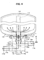
- the heat storage tank 100 has a tank body 110, and the tank body 110 is constructed by a double structure composed of an inner tank portion 111 made of a material having a sufficient corrosion resistance such as a stainless metal, and an outside tank 112. A space between both the tank portions 111, 112 is substantially evacuated to form a heat insulating layer.
- a first pipe member 113 is inserted into a lower side position of the tank body 110 to be welded to both the tank portions 111, 112 of the tank body 110, so that an interior of the tank body 110 communicates with an exterior of the tank body 110 through the first pipe member 113.
- a second pipe member 114 made of a material having a sufficient heat-insulating performance, such as a nylon resin, is disposed in the first pipe member 113 concentrically with the first pipe member 113. The second pipe member 114 is inserted into both the tank portions 111, 112 of the tank body 110 to extend vertically.
- a flow passage 115 (first flow passage) through which cooling water in the second cooling water circuit S2 flows into the tank body 110 is defined between the first pipe member 113 and the second pipe member 114, and the second pipe member 114 defines therein a flow passage (second flow passage) through which cooling water stored in the tank body 110 flows out. Therefore, cooling water flowing from the engine 200 flows into the tank body 110 of the heat storage tank 100 after passing through the flow passage 115 from below upwardly.
- An introduction port 116 is opened in the second pipe member 114 within the tank body 110 at a position upper than the flow passage 115 and lower than a liquid surface of cooling water stored within the tank body 110. Therefore, cooling water introduced into the second pipe member 114 from the introduction port 116 flows through the second pipe member 114 from an upper side downwardly, and then flows to an outside of the tank body 110 of the heat storage tank 100.
- a circular plate member 117 for restricting a mixing of cooling water in the tank body 110 is disposed within the tank body 110 at a lower side lower than the introduction port 116, so that cooling water flowing vertically upwardly from the flow passage 115 collides with the plate member 117.
- the plate member 117 has plural through holes 117a penetrating through the plate member 117 in a thickness direction.
- the through holes 117a are provided in such a manner that radial dimensions of the through holes 117a are increased as the through holes 117 are positioned to a radial outside.
- a housing 118 is disposed at a lower side of the tank body 110.
- the housing 118 defines a flow passage 118a communicating with the flow passage 115, and a flow passage 118b communicating with the flow passage of the second pipe member 114.
- Connection pipes 118c, 118d for connecting a pipe of the second cooling water circuit S2 and the flow passages 118a, 118b are formed in the housing 118.
- the tank body 110 is assembled to the vehicle through the housing 118.
- the housing 118 is made of a material similar to that of the second pipe member 114. while the housing 118 is fixed to the tank body 110, the second pipe member 114 is inserted into the plate member 117 and into the housing 118 to be fixed.
- a ring-plate like first valve body 119 for opening and closing the flow passage 118a is disposed.
- the first valve body 19 is constructed to open the flow passage 118a when dynamical pressure more than a predetermined pressure, due to cooling water, is applied to the first valve body 119 from below, and to close the flow passage 118a when the dynamical pressure lower than the predetermined pressure is applied to the first valve body 119 from below.
- an opening diameter d1 of a first valve port 119a opened and closed by the first valve body 119 is made smaller than an outer diameter of the first valve body 119, and the first valve body 119 is disposed at an upper side of the first valve port 119a.
- a density of the first valve body 119 is made larger than that of cooling water.
- a specific gravity of the first valve 119 is approximately 1.64.
- the first valve port 119a When the first valve port 119a is closed by the first valve body 119, the first valve port 119a (flow passage 118a) is closed by the weight of the first valve body 119 and weight of cooling water above the first valve body 119. Therefore, the flow passage 118a (first valve port 119a) can be accurately closed by the first valve body 119.
- a sphere-shaped second valve body 120 for opening and closing the flow passage 118b (second valve port 120a) is disposed.
- the second valve body 120 is constructed to open the flow passage 118b when dynamical pressure larger than a predetermined pressure, due to cooling water, is applied to the second valve body 120 from an upper side of the second valve body 120, and to close the flow passage 118b when the dynamical pressure lower than the predetermined dynamical pressure is applied to the second valve body 120 from the upper side of the second valve body 120.
- an opening diameter d2 of a second valve port 120a opened and closed by the second valve body 120 is made smaller than an outer diameter D2 of the second valve body 120, and the second valve body 120 is disposed at a lower side of the second valve port 120a.
- a density of the second valve body 120 is made smaller than that of the cooling water. For example, a specific gravity of the second valve 120 is approximately 0.98.
- a valve-closing force for closing the second valve port 120a is a force due to a density difference between the second valve body 120 and the cooling water.
- the valve-closing force is sufficient for preventing a flow of cooling water between an interior of the heat storage tank 100 and an exterior of the heat storage tank 100, due to a temperature difference between the interior and the exterior of the heat storage tank 100.
- the flow passage 118b is bent to have a vertical passage portion 118e extending approximately vertically, and a horizontal passage portion 118f extending approximately horizontally.
- the second valve body 120 and the second valve port 120a are provided in a connection portion where the vertical passage portion 118e and the horizontal passage portion 118f are connected. Accordingly, when the second valve body 120 moves to the lower side due to the dynamical pressure, the horizontal passage 118f may be throttled by the second valve body 120.
- a recessed receiving portion 118g is provided in the housing 118 at a position lower than the connection portion between the vertical passage portion 118e and the horizontal passage portion 118f. Therefore, when the dynamical pressure is applied to the upper side of the second valve body 120 from the upper side, the second valve body 120 is received in the receiving portion 118g, and it can prevent the horizontal passage portion 118f from being restricted.
- both the valve bodies 119, 120 are made of a ternary copolymerization rubber of ethylene, propylene and diene (EPDM).
- EPDM ternary copolymerization rubber of ethylene, propylene and diene
- the heat storage mode is performed, when the engine 200 operates and when the temperature T1 (i.e., temperature detected by the first temperature sensor 251) of cooling water flowing from the engine 200 is equal to or higher than a predetermined temperature To.
- a predetermined temperature To is set at a temperature at which a heating operation of the engine 200 can be considered to be finished in an engine-heating mode.
- the predetermined temperature is 80°C.
- the engine-heating mode is performed when the operation of the engine 200 starts. That is, in the engine-heating mode, at the same time as the start of the engine 200, the second pump 240 is operated. Therefore, in the engine-heating mode, high-temperature cooling water stored in the heat storage tank 100 is supplied to the engine 200, and the heating operation of the engine 200 is facilitated.
- high-temperature cooling water stored in the heat storage tank 100 can be supplied to the heater core 230 from a time immediately after the start of the operation of the engine 200. Therefore, in the heating operation, the passenger compartment can be readily quickly heated.
- the cooling water holding mode is performed when the temperature T2 (i.e., the temperature detected by the second temperature sensor 252) of cooling water flowing from the heat storage tank 100 is lower than the predetermined temperature To when the engine 200 operates.
- the operation of the second pump 240 is stopped.
- the cooling water holding mode is changed from the engine-heating mode when all the high-temperature cooling water stored in the heat storage tank 100 flows out in the engine-heating mode. Therefore, it can prevent low-temperature cooling water flowing from the engine 200 from being stored in the heat storage tank 100 and from flowing into the engine 200. Accordingly, the heating operation of the engine 200 can be further facilitated.
- the heating operation of the engine 200 can be further effectively facilitated.
- the temperature T1 of cooling water flowing from the engine 200 is higher than the predetermined temperature To, the heat storage mode is set from the cooling water holding mode.
- the hot water holding mode is performed when the operation of the engine 200 stops.
- the operation of the second pump 240 stops, and high-temperature cooling water (hot water) stored in the heat storage tank 100 during the heat storage mode is stored by heat insulation.
- hot water high-temperature cooling water
- the first and second valve ports 119a and 120a are opened and closed by the dynamical pressure applied to the first and second valve bodies 119, 120, respectively. Therefore, the structure of a valve portion for controlling a flow of cooling water in the heat storage tank 100 can be made simple, and component number for the valve member can be relatively made smaller. Thus, the heat storage tank 100 can be manufactured in low cost.
- the second cooling water circuit S2 provided with the heat storage tank 100 is provided separately independently with the first cooling water circuit S1 having the heater core 230 and the radiator 210. Therefore, high-temperature cooling water can be directly supplied to the engine 200 from the heat storage tank 100 at a requisite time without being affected by the operation of the heater core 230 or the radiator 210. Thus, the heating operation of the engine 200 can be effectively facilitated.
- the tank body 110 has the double tank structure with a sufficient heat-insulating performance.
- the interior of the tank body 110 is thermally connected to an exterior of the tank body 110. Therefore, heat of hot water (cooling water) in the tank body 110 is readily radiated from the opening portion of the tank body 110.
- the temperature of hot water in the tank body 110 is lowered as a lower position in the tank body 110.
- the opening portion of the tank body 110 is provided at a lower side position of the tank body 110 so that a temperature difference between the interior and the exterior of the tank body 110 is made smaller in the opening portion of the tank body 110. Accordingly, in the first embodiment, a heat radiation from the opening portion of the tank body 110 can be restricted, and heat-insulating performance of the tank body 110 can be improved.
- FIGS. 5 and 6 A second preferred embodiment of the present invention will be now described with reference to FIGS. 5 and 6.
- the second valve body 120 when the second pump 240 operates, the second valve body 120 is pressed by the dynamical pressure applied to the second valve body 120 to be moved downwardly.
- the second valve body 120 may be not moved to the receiving portion 118g, but may be moved to a position (guide member 121) corresponding to the horizontal passage portion 118f as shown in FIG. 5.
- the second valve body 120 is positioned at the position corresponding to the horizontal passage portion 118f as shown in FIG. 5, the flow of cooling water in the horizontal passage portion 118f is restricted by the second valve body 120, and a flow resistance of cooling water is increased.
- a receiving portion 118g for receiving the second valve body 120 is provided at a side opposite to the horizontal passage portion 118f. That is, at both opposite sides of the connection portion between the vertical passage portion 118e and the horizontal passage portion 118f, the horizontal passage portion 118f and the receiving portion 118g are provided opposite to each other.
- a guide portion 118j having a taper surface 118h is provided in the connection portion so that the second valve body 120 moves into the receiving portion 118g by the guiding of the taper surface 118h.
- the second embodiment it can prevent the flow of cooling water from being restricted by the second valve body 120 when the dynamical pressure is applied to second valve body 120, and it can prevent the flow resistance of cooling water from being increased.
- FIGS. 7 and 8 A third preferred embodiment of the present invention will be now described with reference to FIGS. 7 and 8.
- the second valve body 120 is disposed inside the second pipe member 114 to be positioned within the tank body 110. Accordingly, in the third embodiment, the receiving portion 118g described in the first and second embodiments is unnecessary, and a size of the housing 118 can be reduced.
- the second pipe member 114 is provided in such a manner that, a hole diameter d2 of a pipe part from the second valve port 120a toward the introduction port 116 is made smaller than the diameter D2 of the second valve body 120, and a hole diameter d3 of a pipe part from the second valve port 120a toward the housing 110 (downside) is made larger than the diameter D2 of the second valve body 120.
- the second pipe member 114 is provided with a male screw portion (not shown) at a lower side end, and the male screw portion of the second pipe member 114 is screwed into a female screw portion provided in the housing 118 so that the second pipe member 114 is fixed to the housing 118.
- FIG. 7 shows a state where the valve ports 119a, 120a are closed by the first and second valve bodies 119, 120, respectively, when the operation of the second pump 240 stops.
- a collision member 122 to which cooling water flowing from a flow port 115a of the flow passage 115 collides, is provided at a position near the flow port 115a of the flow passage 115.
- the collision member 122 and the plate member 117 described in the first embodiment can be integrally formed by a stainless metal, for example.
- the collision member 122 includes a cover member 122a disposed opposite to the flow port 115a to have a predetermined space between the flow port 115a and the cover member 122a, and a guide portion 122b connected to the cover member 122a to extend downwardly. That is, as shown in FIG. 9, the guide portion 122b connected to the cover member 122a is disposed to cover the flow port 115a around an entire outer periphery of the flow port 115a at a position away from the flow port 115a by a predetermined dimension. Further, in the fourth embodiment, the plate member 117 is provided around the flow port 115a to extend from an end portion of the guide portion 122b to an inner wall of the tank body 110. The cover member 122a of the collision member 122 is used as a stopper member for preventing the first valve body 119 from being away from the flow port 115a more than a predetermined dimension.
- the opening portion of the tank body 110 is made smaller as possible.
- the opening area of the opening portion of the tank body 110 is made smaller, when the flow amount of cooling water flowing into the tank body 110 is made larger, a flow rate of cooling water flowing into the tank body 110 from the opening portion is increased, and cooling water passes through the holes 117a of the plate member 117 when only the plate member 117 described in the first embodiment is disposed in the heat storage tank 100.
- cooling water in the tank body 110 is mixed, and cooling water may forcedly circulate in the tank body 110.
- the collision member 122 having an approximate cup shape is provided around the flow port 115a. Therefore, even when a water flow with a high flow rate is injected toward an upper side from the flow port 115a, the water flow collides with the cover member 122a and are turned by an approximate right angle 90° , and thereafter are turned downwardly. Accordingly, after the flow rate of cooling water from the flow port 115a is sufficiently reduced by the collision member 122, the water flow is introduced to a lower side of the plate member 117.
- the upwardly injected flow of cooling water can be accurately changed so that cooling water from the flow port 115a is introduced at the lower side of the plate member 117. Therefore, even when cooling water having a large flow rate is injected from the flow port 115a, it can prevent cooling water in the tank body 110 from being mixed, while heat-insulating performance of the heat storage tank 100 can be improved.
- the guide portion 122b is provided along all the outer periphery of the flow port 115a, the mixing of cooling water in the tank body 110 can be further effectively prevented.
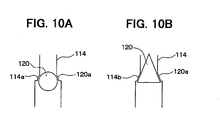
- a valve seat 114a, 114b is provided to define the valve port 120a, so that a surface of the second valve body 120 contacts the valve seat 114a, 114b.
- the valve seat 114a is formed to have a spherical surface.
- the valve seat 114b is formed to have a conical taper shape.
- the valve seat 114a, 114b contacting the second valve body 120 in the second valve port 120a is provided. That is, by providing the valve seat 114a, 114b, a contacting area of the second valve body 120 contacting the second pipe member 114 can be increased, and a heat-transmitting path for transmitting heat from the interior of the heat storage tank 100 to the exterior of the heat storage tank 100 can be elongated. Therefore, heat-insulating capacity of the heat storage tank 100 can be improved.
- the shape of the valve seat 114a, 114b is not limited to the shapes shown in FIGS. 10A and 10B, but can be suitably changed in accordance with the shape of the valve body 120.
- the first valve body 119 and the second valve body 120 are made of a rubber (e.g., EPDM).
- the valve bodies 119, 120 can be made of the other material such as a metal, a resin, a foam member, a hollow member and a sponge member.
- the shapes of the first and second valve bodies 119, 120 can be changed to the other shapes such as a conical shape, a cylindrical shape and a fusiform shape.
- the opening portion of the tank body 110 is provided at a lower side position of the tank body 110 so that the housing 118 and the first pipe member 113 are positioned at the lower side of the tank body 110.
- the housing 118 and the opening of the tank body 110 may be positioned at an upper side of the tank body 110 or may be positioned at the other side.
- the flow passage is closed when the dynamical pressure is smaller than the predetermined pressure by using the density difference between the cooling water and the first and second valve bodies 119, 120.
- an elastic member such as a spring can be disposed so that a force opposite to the dynamical pressure is applied to the first or second valve body 119, 120.
- the flow passage is opened and closed by the valve body 119 or 120 by a balance between the force due to the dynamical pressure and a force due to the elastic member.
- an elastic member can be provided, so that the flow passage is opened and closed by a balance of the force due to the elastic member, the force of the dynamical pressure and the density difference between the cooling water and the valve body 119, 120.
- both the valve bodies 119, 120 are provided in both the flow passages in the heat storage tank 100 at inlet position and an outlet position.
- one valve body can be provided for one flow passage in the heat storage tank 100.
Landscapes
- Engineering & Computer Science (AREA)
- Mechanical Engineering (AREA)
- General Engineering & Computer Science (AREA)
- Physics & Mathematics (AREA)
- Thermal Sciences (AREA)
- Chemical & Material Sciences (AREA)
- Combustion & Propulsion (AREA)
- Life Sciences & Earth Sciences (AREA)
- Atmospheric Sciences (AREA)
- Air-Conditioning For Vehicles (AREA)
- Float Valves (AREA)
Claims (18)
- Wärmespeicherbehälter (100) zum Speichern einer Kühlflüssigkeit eines flüssigkeitsgekühlten Motors (200) in einem Kühlflüssigkeitskreis durch Wärmeisolation, wobei der Wärmespeicherbehälter aufweist:einen Behälterkörper (100), in dem die Kühlflüssigkeit durch Wärmeisolation gespeichert wird;ein mit dem Behälterkörper verbundenes Verbindungselement (113, 114, 118) zum Definieren eines mit einem Innenraum des Behälterkörpers in Verbindung stehenden Fluidkanals (114, 115, 118a, 118b), durch den Kühlflüssigkeit im Kühlflüssigkeitskreis strömt;einen Ventilkörper (119, 120) zum Öffnen und Schließen des Fluidkanals, wobei der Ventilkörper ausgebildet ist, den Fluidkanal zu öffnen, wenn ein dynamischer Druck durch die Kühlflüssigkeit größer als ein vorbestimmter Druck auf den Ventilkörper ausgeübt wird, und den Fluidkanal zu schließen, wenn der dynamische Druck kleiner als der vorbestimmte Druck auf den Ventilkörper ausgeübt wird, wobeider Fluidkanal (114, 115, 118a, 118b) einen ersten Fluidkanal (115, 118a), durch den die Kühlflüssigkeit im Kühlflüssigkeitskreis im Behälterkörper nach oben strömt, und einen zweiten Fluidkanal (114, 118b), durch den die Kühlflüssigkeit aus dem Behälterkörper nach unten ausströmt, enthält,der Ventilkörper (119, 120) einen ersten Ventilkörper (119) zum Öffnen und Schließen des ersten Fluidkanals und einen zweiten Ventilkörper (120) zum Öffnen und Schließen des zweiten Fluidkanals enthält,das Verbindungselement (113, 114, 118) so angeordnet ist, dass die Kühlflüssigkeit im Behälterkörper durch den zweiten Fluidkanal (114, 118b) nach unten ausströmt,der zweite Ventilkörper (120) eine Dichte kleiner als jene der Kühlflüssigkeit besitzt, um einen Dichteunterschied zwischen der Kühlflüssigkeit und dem zweiten Ventilkörper zu haben, undder zweite Ventilkörper (120) so angeordnet ist, dass er den zweiten Fluidkanal öffnet, wenn der dynamische Druck größer als der vorbestimmte Druck auf eine obere Seite des zweiten Ventilkörpers ausgeübt wird, und den Fluidkanal durch den Dichteunterschied schließt, wenn der auf die Oberseite des zweiten Ventilkörpers ausgeübte dynamische Druck kleiner als der vorbestimmte Druck ist.
- Wärmespeicherbehälter nach Anspruch 1, bei welchem der erste Ventilkörper (119) so ausgebildet ist, dass er den ersten Fluidkanal durch einen Dichteunterschied zwischen der Kühlflüssigkeit und dem ersten Ventilkörper schließt, wenn der auf den ersten Ventilkörper ausgeübte dynamische Druck kleiner als der vorbestimmte Druck ist.
- Wärmespeicherbehälter nach Anspruch 1, bei welchem der erste Ventilkörper (119) so ausgebildet ist, dass er den ersten Fluidkanal durch einen Druck aufgrund eines Gewichts des ersten Ventilkörpers und eines Gewichts der Kühlflüssigkeit schließt, wenn der auf den ersten Ventilkörper ausgeübte dynamische Druck kleiner als der vorbestimmte Druck ist.
- Wärmespeicherbehälter nach einem der Ansprüche 1 bis 3, bei welchem das Verbindungselement (113, 114, 118) so angeordnet ist, dass es mit einem Unterseitenabschnitt des Behälterkörpers in einer solchen Weise verbunden ist, dass der erste Fluidkanal und der zweite Fluidkanal mit dem Innenraum des Behälterkörpers an einer unteren Seite im Behälterkörper in Verbindung stehen.
- Wärmespeicherbehälter nach Anspruch 1, bei welchem
das Verbindungselement (113, 114, 118) so angeordnet ist, dass die Kühlflüssigkeit im Kühlflüssigkeitskreis durch den ersten Fluidkanal (115, 118a) von unten nach oben in den Behälterkörper strömt;
der erste Ventilkörper (119) eine Dichte größer als jene der Kühlflüssigkeit besitzt, um einen Dichteunterschied zwischen dem ersten Ventilkörper und der Kühlflüssigkeit zu haben; und
der erste Ventilkörper so angeordnet ist, dass er den ersten Fluidkanal öffnet, wenn der dynamische Druck größer als der vorbestimmte Druck auf eine untere Seite des ersten Ventilkörpers ausgeübt wird, und den ersten Fluidkanal durch den Dichteunterschied schließt, wenn der auf die untere Seite des ersten Ventilkörpers ausgeübte dynamische Druck kleiner als der vorbestimmte Druck ist. - Wärmespeicherbehälter nach einem der Ansprüche 1 bis 5, ferner mit einem Kollisionselement (122), das im Behälterkörper so angeordnet ist, dass die von einer Fluidöffnung des Fluidkanals in den Behälterkörper strömende Kühlflüssigkeit mit dem Kollisionselement zusammenstößt, wobei das Kollisionselement ein Abdeckelement (122a), das gegenüber der Strömungsöffnung an einer Position um einen vorbestimmten Abstand entfernt von der Strömungsöffnung angeordnet ist, und ein Führungselement (122b), das sich von dem Abdeckelement zu einer Umfangsseite der Fluidöffnung erstreckt, aufweist.
- Wärmespeicherbehälter nach Anspruch 6, bei welchem das Führungselement (122b) an einer Position um einen vorbestimmten Abstand von der Strömungsöffnung entfernt angeordnet ist, um die Strömungsöffnung entlang eines gesamten Außenumfangs der Fluidöffnung abzudecken.
- Wärmespeicherbehälter nach einem der Ansprüche 6 und 7, ferner mit einem Plattenelement (117) mit mehreren Löchern zum Beschränken eines Mischens der Kühlflüssigkeit im Behälterkörper, wenn die Kühlflüssigkeit von der Fluidöffnung in den Behälterkörper strömt, wobei das Plattenelement zwischen dem Kollisionselement und einer Innenwand des Behälterkörpers um die Fluidöffnung herum angeordnet ist.
- Wärmespeicherbehälter nach Anspruch 8, bei welchem das Kollisionselement und das Plattenelement integral ausgebildet sind.
- Wärmespeicherbehälter nach einem der Ansprüche 1 bis 9, bei welchem
der erste Fluidkanal eine erste Ventilöffnung (119a) aufweist, die durch einen Wandabschnitt definiert ist, der den ersten Ventilkörper kontaktiert, wenn der erste Fluidkanal durch den ersten Ventilkörper geschlossen ist, und
der zweite Fluidkanal eine zweite Ventilöffnung (120a) aufweist, die durch einen Wandabschnitt definiert ist, der den zweiten Ventilkörper kontaktiert, wenn der zweite Fluidkanal durch den zweiten Ventilkörper geschlossen ist. - Wärmespeicherbehälter nach Anspruch 10, bei welchem der die zweite Ventilöffnung (120a) definierende Wandabschnitt einen Ventilsitz aufweist, mit dem eine Oberfläche des zweiten Ventilkörpers in Kontakt ist, wenn der zweite Fluidkanal durch den zweiten Ventilkörper geschlossen ist.
- Wärmespeicherbehälter nach Anspruch 1, bei welchem
der erste Ventilkörper (119) eine Dichte größer als jene der Kühlflüssigkeit besitzt, und
der erste Ventilkörper so angeordnet ist, dass er den ersten Fluidkanal öffnet, wenn ein dynamischer Druck durch die Kühlflüssigkeit größer als ein vorbestimmter Druck auf den ersten Ventilkörper von einer unteren Seite ausgeübt wird, und den ersten Fluidkanal schließt, wenn der auf den ersten Ventilkörper ausgeübte dynamische Druck kleiner als der vorbestimmte Druck ist. - Wärmespeicherbehälter nach Anspruch 12, bei welchem der erste Fluidkanal und der zweite Fluidkanal an einer unteren Seite des Behälterkörpers vorgesehen sind, um mit dem Innenraum des Behälterkörpers in Verbindung zu stehen.
- Wärmespeicherbehälter nach einem der Ansprüche 12 und 13, ferner mit einem Kollisionselement (122), das in dem Behälterkörper so angeordnet ist, dass die von einer Fluidöffnung des ersten Fluidkanals in den Behälterkörper strömende Kühlflüssigkeit mit dem Kollisionselement zusammenstößt, wobei das Kollisionselement ein Abdeckelement (122a), das gegenüber der Fluidöffnung an einer um einen vorbestimmten Abstand von der Fluidöffnung entfernten Position angeordnet ist, und ein Führungselement (122b), das sich von dem Abdeckelement zu einer Umfangsseite der Fluidöffnung erstreckt, aufweist.
- Wärmespeicherbehälter nach Anspruch 14, bei welchem das Führungselement an einer Position um einen vorbestimmten Abstand von der Fluidöffnung entfernt angeordnet ist, um die Fluidöffnung entlang eines gesamten Außenumfangs der Fluidöffnung abzudecken.
- Wärmespeicherbehälter nach einem der Ansprüche 14 und 15, ferner mit einem Plattenelement (117) mit mehreren Löchern zum Beschränken eines Mischens der Kühlflüssigkeit im Behälterkörper, wenn die Kühlflüssigkeit von der Fluidöffnung in den Behälterkörper strömt, wobei das Plattenelement zwischen dem Kollisionselement und einer Innenwand des Behälterkörpers um die Fluidöffnung herum angeordnet ist.
- Wärmespeicherbehälter nach Anspruch 16, bei welchem das Kollisionselement und das Plattenelement integral ausgebildet sind.
- Wärmespeicherbehälter nach einem der Ansprüche 12 bis 17, bei welchem
der erste Fluidkanal eine erste Ventilöffnung besitzt, die durch einen ersten Wandabschnitt definiert ist, der eine Oberfläche des ersten Ventilkörpers kontaktiert, wenn der erste Fluidkanal durch den ersten Ventilkörper geschlossen ist; und
der erste Fluidkanal eine zweite Ventilöffnung besitzt, die durch einen zweiten Wandabschnitt definiert ist, der eine Oberfläche des zweiten Ventilkörpers kontaktiert, wenn der zweite Fluidkanal durch den zweiten Ventilkörper geschlossen ist.
Applications Claiming Priority (4)
| Application Number | Priority Date | Filing Date | Title |
|---|---|---|---|
| JP2000310869 | 2000-10-11 | ||
| JP2000310869 | 2000-10-11 | ||
| JP2001226223 | 2001-07-26 | ||
| JP2001226223A JP2002188442A (ja) | 2000-10-11 | 2001-07-26 | 蓄熱タンク |
Publications (3)
| Publication Number | Publication Date |
|---|---|
| EP1197645A2 EP1197645A2 (de) | 2002-04-17 |
| EP1197645A3 EP1197645A3 (de) | 2004-01-21 |
| EP1197645B1 true EP1197645B1 (de) | 2007-07-04 |
Family
ID=26601893
Family Applications (1)
| Application Number | Title | Priority Date | Filing Date |
|---|---|---|---|
| EP01123333A Expired - Lifetime EP1197645B1 (de) | 2000-10-11 | 2001-10-08 | Wärmespeicherbehälter für einen Kühlwasserkreislauf |
Country Status (4)
| Country | Link |
|---|---|
| US (1) | US6477990B2 (de) |
| EP (1) | EP1197645B1 (de) |
| JP (1) | JP2002188442A (de) |
| DE (1) | DE60129194T2 (de) |
Cited By (1)
| Publication number | Priority date | Publication date | Assignee | Title |
|---|---|---|---|---|
| GB2525415A (en) * | 2014-04-24 | 2015-10-28 | Ford Global Tech Llc | An Engine Cooling System Expansion Reservoir |
Families Citing this family (16)
| Publication number | Priority date | Publication date | Assignee | Title |
|---|---|---|---|---|
| JP3867550B2 (ja) * | 2001-07-04 | 2007-01-10 | 株式会社日本自動車部品総合研究所 | 蓄熱タンク |
| JP4513245B2 (ja) * | 2001-09-06 | 2010-07-28 | 株式会社デンソー | 蓄熱タンク |
| DE10234608A1 (de) * | 2002-07-30 | 2004-02-19 | Robert Bosch Gmbh | Verfahren zum Betrieb eines Kühl- und Heizkreislaufs eines Kraftfahrzeugs |
| JP3996079B2 (ja) * | 2003-03-31 | 2007-10-24 | 株式会社デンソー | 蓄熱タンク |
| JP3897723B2 (ja) | 2003-03-31 | 2007-03-28 | トヨタ自動車株式会社 | 蓄熱タンク |
| JP4103663B2 (ja) * | 2003-03-31 | 2008-06-18 | トヨタ自動車株式会社 | エンジンの冷却装置 |
| JP3905484B2 (ja) | 2003-03-31 | 2007-04-18 | トヨタ自動車株式会社 | 蓄熱タンクの取付け構造 |
| JP4003685B2 (ja) | 2003-04-09 | 2007-11-07 | トヨタ自動車株式会社 | エンジンの冷却装置 |
| JP2006233765A (ja) * | 2005-02-22 | 2006-09-07 | Denso Corp | 蓄熱タンク |
| DE102006017246A1 (de) * | 2005-04-18 | 2006-10-19 | Denso Corp., Kariya | Abwärmenutzungssystem für einen Kraftfahrzeugmotor |
| JP4755572B2 (ja) * | 2006-11-28 | 2011-08-24 | カルソニックカンセイ株式会社 | 車両用蓄熱システム |
| JP5178422B2 (ja) * | 2008-09-16 | 2013-04-10 | カルソニックカンセイ株式会社 | 蓄熱装置及びその製造方法 |
| WO2010051182A1 (en) * | 2008-10-29 | 2010-05-06 | Icl-Ip America Inc. | Phosphorus-containing flame retardant epoxy resin composition, prepeg and laminate thereof |
| DE102012204988A1 (de) * | 2012-03-28 | 2013-10-02 | Ford Global Technologies, Llc | Wärmespeicher für ein Kühlmittel eines Fahrzeugmotors |
| EP2786921B1 (de) | 2013-04-04 | 2017-09-20 | MAGNA STEYR Engineering AG & Co KG | Klebeverbindung eines ersten Hohlprofils mit einem zweiten Hohlprofil |
| GB2534878A (en) * | 2015-02-02 | 2016-08-10 | Isis Innovation | Improvements in fluid storage systems |
Family Cites Families (9)
| Publication number | Priority date | Publication date | Assignee | Title |
|---|---|---|---|---|
| US3498539A (en) * | 1968-04-22 | 1970-03-03 | Heinz W Boehmfeld | Heating system for internal combustion engines |
| FR2443346A1 (fr) * | 1978-12-06 | 1980-07-04 | Lenga Sarl | Dispositif pour obtenir rapidement une temperature desiree en un point d'un vehicule automobile apres une periode d'arret de celui-ci |
| DE3624261C2 (de) * | 1986-07-18 | 1995-02-09 | Kloeckner Waermetechnik | Warmwasserspeicher, insbesondere Schichtenspeicher |
| DD263113A1 (de) * | 1987-07-20 | 1988-12-21 | Schwerin Energiekombinat | Anordnung zur wirbelfreien einleitung von speichermedien in schichtwaermespeicherbehaelter |
| AT389385B (de) * | 1987-12-11 | 1989-11-27 | Vaillant Gmbh | Warmwasserspeicher |
| JP2827208B2 (ja) | 1987-12-26 | 1998-11-25 | 株式会社デンソー | 車両用温水式暖房装置 |
| SE9500964L (sv) * | 1994-11-14 | 1996-02-26 | Jens Thurfjell | Värmelagringsanordning vid en vätskekyld förbränningsmotor |
| JPH1077839A (ja) | 1996-08-30 | 1998-03-24 | Denso Corp | 冷却水制御弁および内燃機関の冷却水回路 |
| US5896833A (en) | 1996-08-30 | 1999-04-27 | Denso Corporation | Cooling water circuit system and cooling water control valve |
-
2001
- 2001-07-26 JP JP2001226223A patent/JP2002188442A/ja not_active Withdrawn
- 2001-10-04 US US09/970,915 patent/US6477990B2/en not_active Expired - Fee Related
- 2001-10-08 DE DE60129194T patent/DE60129194T2/de not_active Expired - Lifetime
- 2001-10-08 EP EP01123333A patent/EP1197645B1/de not_active Expired - Lifetime
Cited By (3)
| Publication number | Priority date | Publication date | Assignee | Title |
|---|---|---|---|---|
| GB2525415A (en) * | 2014-04-24 | 2015-10-28 | Ford Global Tech Llc | An Engine Cooling System Expansion Reservoir |
| US9909487B2 (en) | 2014-04-24 | 2018-03-06 | Ford Global Technologies, Llc | Systems and methods for an engine cooling system expansion reservoir |
| GB2525415B (en) * | 2014-04-24 | 2018-05-16 | Ford Global Tech Llc | An Engine Cooling System Expansion Reservoir |
Also Published As
| Publication number | Publication date |
|---|---|
| JP2002188442A (ja) | 2002-07-05 |
| US20020040693A1 (en) | 2002-04-11 |
| DE60129194D1 (de) | 2007-08-16 |
| EP1197645A3 (de) | 2004-01-21 |
| DE60129194T2 (de) | 2008-03-13 |
| EP1197645A2 (de) | 2002-04-17 |
| US6477990B2 (en) | 2002-11-12 |
Similar Documents
| Publication | Publication Date | Title |
|---|---|---|
| EP1197645B1 (de) | Wärmespeicherbehälter für einen Kühlwasserkreislauf | |
| EP1273466B1 (de) | Wärmespeicherbehälter | |
| CN110997405B (zh) | 车辆、车辆用冰箱和用于控制车辆用冰箱的方法 | |
| US9682607B2 (en) | Air conditioner for vehicle | |
| CN109690221A (zh) | 设备温度调节装置 | |
| US10957951B2 (en) | Temperature control device for a battery of a vehicle, vehicle having such a temperature control device and method for controlling the temperature of a battery of a vehicle | |
| EP3835693A1 (de) | Kühlschrank | |
| CN218367329U (zh) | 热管理集成模块、热管理系统及车辆 | |
| CN104943508B (zh) | 汽车室内调温装置及其调温方法 | |
| JP7203794B2 (ja) | 車両の回路温度調整システム | |
| US6718925B2 (en) | Heat storage tank | |
| CN211748907U (zh) | 一种防凝露的冰箱饮水机水嘴 | |
| CN116164435B (zh) | 宽范围快温变密闭液体导热循环系统、温度控制及安全管理方法 | |
| KR20210054874A (ko) | 액화 산소를 이용한 냉각 시스템 | |
| CN114122478A (zh) | 燃料电池组件和车辆用的燃料电池 | |
| CN218584703U (zh) | 一种冷热温控水分活度测定仪 | |
| KR20100057336A (ko) | 축냉 열교환기 | |
| CN221844391U (zh) | 冷暖水毯 | |
| JP2827208B2 (ja) | 車両用温水式暖房装置 | |
| US20220393271A1 (en) | Battery temperature regulating apparatus | |
| KR101734775B1 (ko) | Lpg 연료 차량의 충전 장치 및 방법 | |
| CN101535752B (zh) | 具有水箱的制冷器具 | |
| CN113067058B (zh) | 一种软包电池热管理系统及其操作方法 | |
| CN115179836B (zh) | 扶手箱调温装置及车辆 | |
| CN118046712A (zh) | 热管理集成模块、热管理系统及车辆 |
Legal Events
| Date | Code | Title | Description |
|---|---|---|---|
| PUAI | Public reference made under article 153(3) epc to a published international application that has entered the european phase |
Free format text: ORIGINAL CODE: 0009012 |
|
| AK | Designated contracting states |
Kind code of ref document: A2 Designated state(s): AT BE CH CY DE DK ES FI FR GB GR IE IT LI LU MC NL PT SE TR |
|
| AX | Request for extension of the european patent |
Free format text: AL;LT;LV;MK;RO;SI |
|
| PUAL | Search report despatched |
Free format text: ORIGINAL CODE: 0009013 |
|
| AK | Designated contracting states |
Kind code of ref document: A3 Designated state(s): AT BE CH CY DE DK ES FI FR GB GR IE IT LI LU MC NL PT SE TR |
|
| AX | Request for extension of the european patent |
Extension state: AL LT LV MK RO SI |
|
| RIC1 | Information provided on ipc code assigned before grant |
Ipc: 7F 01P 11/20 B Ipc: 7F 28D 20/00 B Ipc: 7F 28F 27/02 B Ipc: 7F 01P 11/02 A |
|
| 17P | Request for examination filed |
Effective date: 20040226 |
|
| AKX | Designation fees paid |
Designated state(s): DE FR GB |
|
| GRAP | Despatch of communication of intention to grant a patent |
Free format text: ORIGINAL CODE: EPIDOSNIGR1 |
|
| GRAS | Grant fee paid |
Free format text: ORIGINAL CODE: EPIDOSNIGR3 |
|
| GRAA | (expected) grant |
Free format text: ORIGINAL CODE: 0009210 |
|
| AK | Designated contracting states |
Kind code of ref document: B1 Designated state(s): DE FR GB |
|
| REG | Reference to a national code |
Ref country code: GB Ref legal event code: FG4D |
|
| REF | Corresponds to: |
Ref document number: 60129194 Country of ref document: DE Date of ref document: 20070816 Kind code of ref document: P |
|
| ET | Fr: translation filed | ||
| PLBE | No opposition filed within time limit |
Free format text: ORIGINAL CODE: 0009261 |
|
| STAA | Information on the status of an ep patent application or granted ep patent |
Free format text: STATUS: NO OPPOSITION FILED WITHIN TIME LIMIT |
|
| REG | Reference to a national code |
Ref country code: GB Ref legal event code: 746 Effective date: 20080424 |
|
| 26N | No opposition filed |
Effective date: 20080407 |
|
| PGFP | Annual fee paid to national office [announced via postgrant information from national office to epo] |
Ref country code: DE Payment date: 20091001 Year of fee payment: 9 |
|
| PGFP | Annual fee paid to national office [announced via postgrant information from national office to epo] |
Ref country code: FR Payment date: 20091029 Year of fee payment: 9 Ref country code: GB Payment date: 20091007 Year of fee payment: 9 |
|
| GBPC | Gb: european patent ceased through non-payment of renewal fee |
Effective date: 20101008 |
|
| PG25 | Lapsed in a contracting state [announced via postgrant information from national office to epo] |
Ref country code: FR Free format text: LAPSE BECAUSE OF NON-PAYMENT OF DUE FEES Effective date: 20101102 |
|
| REG | Reference to a national code |
Ref country code: FR Ref legal event code: ST Effective date: 20110630 |
|
| PG25 | Lapsed in a contracting state [announced via postgrant information from national office to epo] |
Ref country code: GB Free format text: LAPSE BECAUSE OF NON-PAYMENT OF DUE FEES Effective date: 20101008 |
|
| REG | Reference to a national code |
Ref country code: DE Ref legal event code: R119 Ref document number: 60129194 Country of ref document: DE Effective date: 20110502 |
|
| PG25 | Lapsed in a contracting state [announced via postgrant information from national office to epo] |
Ref country code: DE Free format text: LAPSE BECAUSE OF NON-PAYMENT OF DUE FEES Effective date: 20110502 |