EP1196680B1 - Vorrichtung und verfahren zur abgasnachbehandlung mittels einer aktiven katalytischen reduktion bei einer brennkraftmaschine - Google Patents
Vorrichtung und verfahren zur abgasnachbehandlung mittels einer aktiven katalytischen reduktion bei einer brennkraftmaschine Download PDFInfo
- Publication number
- EP1196680B1 EP1196680B1 EP00954290A EP00954290A EP1196680B1 EP 1196680 B1 EP1196680 B1 EP 1196680B1 EP 00954290 A EP00954290 A EP 00954290A EP 00954290 A EP00954290 A EP 00954290A EP 1196680 B1 EP1196680 B1 EP 1196680B1
- Authority
- EP
- European Patent Office
- Prior art keywords
- pressure sensor
- reducing agent
- reducing
- pressure
- sensor
- Prior art date
- Legal status (The legal status is an assumption and is not a legal conclusion. Google has not performed a legal analysis and makes no representation as to the accuracy of the status listed.)
- Expired - Lifetime
Links
Images

Classifications
-
- F—MECHANICAL ENGINEERING; LIGHTING; HEATING; WEAPONS; BLASTING
- F01—MACHINES OR ENGINES IN GENERAL; ENGINE PLANTS IN GENERAL; STEAM ENGINES
- F01N—GAS-FLOW SILENCERS OR EXHAUST APPARATUS FOR MACHINES OR ENGINES IN GENERAL; GAS-FLOW SILENCERS OR EXHAUST APPARATUS FOR INTERNAL-COMBUSTION ENGINES
- F01N3/00—Exhaust or silencing apparatus having means for purifying, rendering innocuous, or otherwise treating exhaust
- F01N3/08—Exhaust or silencing apparatus having means for purifying, rendering innocuous, or otherwise treating exhaust for rendering innocuous
- F01N3/10—Exhaust or silencing apparatus having means for purifying, rendering innocuous, or otherwise treating exhaust for rendering innocuous by thermal or catalytic conversion of noxious components of exhaust
- F01N3/18—Exhaust or silencing apparatus having means for purifying, rendering innocuous, or otherwise treating exhaust for rendering innocuous by thermal or catalytic conversion of noxious components of exhaust characterised by methods of operation; Control
- F01N3/20—Exhaust or silencing apparatus having means for purifying, rendering innocuous, or otherwise treating exhaust for rendering innocuous by thermal or catalytic conversion of noxious components of exhaust characterised by methods of operation; Control specially adapted for catalytic conversion
- F01N3/206—Adding periodically or continuously substances to exhaust gases for promoting purification, e.g. catalytic material in liquid form, NOx reducing agents
- F01N3/208—Control of selective catalytic reduction [SCR], e.g. by adjusting the dosing of reducing agent
-
- B—PERFORMING OPERATIONS; TRANSPORTING
- B01—PHYSICAL OR CHEMICAL PROCESSES OR APPARATUS IN GENERAL
- B01D—SEPARATION
- B01D53/00—Separation of gases or vapours; Recovering vapours of volatile solvents from gases; Chemical or biological purification of waste gases, e.g. engine exhaust gases, smoke, fumes, flue gases, aerosols
- B01D53/34—Chemical or biological purification of waste gases
- B01D53/92—Chemical or biological purification of waste gases of engine exhaust gases
- B01D53/94—Chemical or biological purification of waste gases of engine exhaust gases by catalytic processes
- B01D53/9404—Removing only nitrogen compounds
- B01D53/9409—Nitrogen oxides
- B01D53/9431—Processes characterised by a specific device
-
- F—MECHANICAL ENGINEERING; LIGHTING; HEATING; WEAPONS; BLASTING
- F01—MACHINES OR ENGINES IN GENERAL; ENGINE PLANTS IN GENERAL; STEAM ENGINES
- F01N—GAS-FLOW SILENCERS OR EXHAUST APPARATUS FOR MACHINES OR ENGINES IN GENERAL; GAS-FLOW SILENCERS OR EXHAUST APPARATUS FOR INTERNAL-COMBUSTION ENGINES
- F01N13/00—Exhaust or silencing apparatus characterised by constructional features
- F01N13/009—Exhaust or silencing apparatus characterised by constructional features having two or more separate purifying devices arranged in series
- F01N13/0097—Exhaust or silencing apparatus characterised by constructional features having two or more separate purifying devices arranged in series the purifying devices are arranged in a single housing
-
- G—PHYSICS
- G01—MEASURING; TESTING
- G01L—MEASURING FORCE, STRESS, TORQUE, WORK, MECHANICAL POWER, MECHANICAL EFFICIENCY, OR FLUID PRESSURE
- G01L19/00—Details of, or accessories for, apparatus for measuring steady or quasi-steady pressure of a fluent medium insofar as such details or accessories are not special to particular types of pressure gauges
- G01L19/0007—Fluidic connecting means
- G01L19/0023—Fluidic connecting means for flowthrough systems having a flexible pressure transmitting element
-
- F—MECHANICAL ENGINEERING; LIGHTING; HEATING; WEAPONS; BLASTING
- F01—MACHINES OR ENGINES IN GENERAL; ENGINE PLANTS IN GENERAL; STEAM ENGINES
- F01N—GAS-FLOW SILENCERS OR EXHAUST APPARATUS FOR MACHINES OR ENGINES IN GENERAL; GAS-FLOW SILENCERS OR EXHAUST APPARATUS FOR INTERNAL-COMBUSTION ENGINES
- F01N2610/00—Adding substances to exhaust gases
- F01N2610/02—Adding substances to exhaust gases the substance being ammonia or urea
-
- F—MECHANICAL ENGINEERING; LIGHTING; HEATING; WEAPONS; BLASTING
- F01—MACHINES OR ENGINES IN GENERAL; ENGINE PLANTS IN GENERAL; STEAM ENGINES
- F01N—GAS-FLOW SILENCERS OR EXHAUST APPARATUS FOR MACHINES OR ENGINES IN GENERAL; GAS-FLOW SILENCERS OR EXHAUST APPARATUS FOR INTERNAL-COMBUSTION ENGINES
- F01N2610/00—Adding substances to exhaust gases
- F01N2610/14—Arrangements for the supply of substances, e.g. conduits
- F01N2610/1453—Sprayers or atomisers; Arrangement thereof in the exhaust apparatus
- F01N2610/146—Control thereof, e.g. control of injectors or injection valves
-
- F—MECHANICAL ENGINEERING; LIGHTING; HEATING; WEAPONS; BLASTING
- F01—MACHINES OR ENGINES IN GENERAL; ENGINE PLANTS IN GENERAL; STEAM ENGINES
- F01N—GAS-FLOW SILENCERS OR EXHAUST APPARATUS FOR MACHINES OR ENGINES IN GENERAL; GAS-FLOW SILENCERS OR EXHAUST APPARATUS FOR INTERNAL-COMBUSTION ENGINES
- F01N2900/00—Details of electrical control or of the monitoring of the exhaust gas treating apparatus
- F01N2900/06—Parameters used for exhaust control or diagnosing
- F01N2900/18—Parameters used for exhaust control or diagnosing said parameters being related to the system for adding a substance into the exhaust
- F01N2900/1806—Properties of reducing agent or dosing system
- F01N2900/1808—Pressure
-
- F—MECHANICAL ENGINEERING; LIGHTING; HEATING; WEAPONS; BLASTING
- F01—MACHINES OR ENGINES IN GENERAL; ENGINE PLANTS IN GENERAL; STEAM ENGINES
- F01N—GAS-FLOW SILENCERS OR EXHAUST APPARATUS FOR MACHINES OR ENGINES IN GENERAL; GAS-FLOW SILENCERS OR EXHAUST APPARATUS FOR INTERNAL-COMBUSTION ENGINES
- F01N2900/00—Details of electrical control or of the monitoring of the exhaust gas treating apparatus
- F01N2900/06—Parameters used for exhaust control or diagnosing
- F01N2900/18—Parameters used for exhaust control or diagnosing said parameters being related to the system for adding a substance into the exhaust
- F01N2900/1806—Properties of reducing agent or dosing system
- F01N2900/1811—Temperature
-
- F—MECHANICAL ENGINEERING; LIGHTING; HEATING; WEAPONS; BLASTING
- F01—MACHINES OR ENGINES IN GENERAL; ENGINE PLANTS IN GENERAL; STEAM ENGINES
- F01N—GAS-FLOW SILENCERS OR EXHAUST APPARATUS FOR MACHINES OR ENGINES IN GENERAL; GAS-FLOW SILENCERS OR EXHAUST APPARATUS FOR INTERNAL-COMBUSTION ENGINES
- F01N2900/00—Details of electrical control or of the monitoring of the exhaust gas treating apparatus
- F01N2900/06—Parameters used for exhaust control or diagnosing
- F01N2900/18—Parameters used for exhaust control or diagnosing said parameters being related to the system for adding a substance into the exhaust
- F01N2900/1806—Properties of reducing agent or dosing system
- F01N2900/1814—Tank level
-
- Y—GENERAL TAGGING OF NEW TECHNOLOGICAL DEVELOPMENTS; GENERAL TAGGING OF CROSS-SECTIONAL TECHNOLOGIES SPANNING OVER SEVERAL SECTIONS OF THE IPC; TECHNICAL SUBJECTS COVERED BY FORMER USPC CROSS-REFERENCE ART COLLECTIONS [XRACs] AND DIGESTS
- Y02—TECHNOLOGIES OR APPLICATIONS FOR MITIGATION OR ADAPTATION AGAINST CLIMATE CHANGE
- Y02A—TECHNOLOGIES FOR ADAPTATION TO CLIMATE CHANGE
- Y02A50/00—TECHNOLOGIES FOR ADAPTATION TO CLIMATE CHANGE in human health protection, e.g. against extreme weather
- Y02A50/20—Air quality improvement or preservation, e.g. vehicle emission control or emission reduction by using catalytic converters
-
- Y—GENERAL TAGGING OF NEW TECHNOLOGICAL DEVELOPMENTS; GENERAL TAGGING OF CROSS-SECTIONAL TECHNOLOGIES SPANNING OVER SEVERAL SECTIONS OF THE IPC; TECHNICAL SUBJECTS COVERED BY FORMER USPC CROSS-REFERENCE ART COLLECTIONS [XRACs] AND DIGESTS
- Y02—TECHNOLOGIES OR APPLICATIONS FOR MITIGATION OR ADAPTATION AGAINST CLIMATE CHANGE
- Y02T—CLIMATE CHANGE MITIGATION TECHNOLOGIES RELATED TO TRANSPORTATION
- Y02T10/00—Road transport of goods or passengers
- Y02T10/10—Internal combustion engine [ICE] based vehicles
- Y02T10/12—Improving ICE efficiencies
Definitions
- the invention relates to a device and a method for Exhaust gas aftertreatment in an internal combustion engine according to the preambles of claims 1 and 7 respectively.
- the reduction of the nitrogen oxide emission of an internal combustion engine operating in excess of air, in particular a diesel internal combustion engine, can take place with the aid of the selective catalytic reduction (SCR) technology to form atmospheric nitrogen (N 2 ) and water vapor (H 2 O).
- SCR selective catalytic reduction
- urea serves as an ammonia carrier and is injected by means of a dosing system in front of a hydrolysis in the exhaust system, where it is converted by hydrolysis to ammonia, which in turn reduces the nitrogen oxides in the actual SCR or DENOX catalyst.
- Such a dosing system has as essential components a reducing agent tank, a pump, a pressure regulator, a pressure sensor and a metering valve on.
- the pump promotes the stored in the reducing agent tank reducing agent to the metering valve, by means of which the reducing agent in the exhaust stream upstream of the hydrolysis catalyst is injected.
- the dosing valve is via signals a control device controlled such that dependent of operating parameters of the internal combustion engine a specific, currently supplied amount of reducing agent becomes (DE 197 43 337 C1).
- urea solution as is typical in SCR systems is used as a reducing agent, has a freezing point from -11 ° C to. Therefore, devices for Heating the dosing be provided to the functionality of all system components after a system startup Ambient temperatures below -11 ° C in an acceptable time ensure and prevent system components during Freeze the factory.
- One of the main components is the urea pressure sensor.
- this pressure sensor continuously the urea pressure system is monitored;
- the connecting hoses or the metering valve must be this Pressure sensor reliably thawed and kept frost-free.
- the pressure sensor element is expediently in spatial Proximity to the control electronics for the dosing system and in installed near the pump outlet. Nevertheless, it is not or only with difficulty, the pressure sensor only via the heater of reducing agent line, reducing agent pump and self-heating thaw the control electronics.
- From DE 44 32 577 A1 discloses a device for avoidance from frost damage to parts of one of the principle of selective catalytic reduction working exhaust gas scrubber during downtime and the possibility of the Operation of such plants below the freezing point of used reducing agent solution known.
- the reservoir and the supply line are by means of an electric heater, which supplies a heat exchanger with heat, heated.
- JP-A61073382 is a method for temperature compensation a semiconductor pressure sensor described on the Diafragmaober Structure
- several resistors are applied and which are used for pressure measurement.
- Compensation resistors provided to change the Ambient temperature in the pressure measurement to eliminate.
- These heating elements are used for temperature compensation with changing. ambient temperature and not for heating the pressure sensor membrane. Therefore, these heating elements are outside the sensor membrane applied.
- the invention is based on the object, a device and specify a method with or with the frost damage be avoided on parts of an exhaust aftertreatment system, both during downtime and during operation such a plant at temperatures below freezing the reducing agent solution used.
- the idea underlying the invention is based, the Pressure sensor membrane as a carrier for heating resistors and the Temperature measurement to use.
- the technology for production The sensor resistor network is used to add in addition Apply heating and temperature measuring resistors.
- the electrical heating resistors make it possible to directly To heat sensor membrane and thus the availability of the Ensure pressure sensor as soon as possible and the pressure to monitor the urea system during the thawing phase.
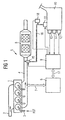
- Figure 1 is very simplified in the form of a block diagram an operated with excess air internal combustion engine shown with an associated exhaust aftertreatment system. Only those parts are shown, which are for the understanding of the invention are necessary. Especially is dispensed with the representation of the fuel circuit Service.
- this embodiment is as an internal combustion engine a diesel engine shown and as a reducing agent for aftertreatment of the exhaust gas is aqueous Urea solution used.
- the internal combustion engine 1 is via a suction line 2 the supplied necessary for combustion air.
- An injection system for example, as a high-pressure storage injection system (Common rail) be formed with injection valves can, the fuel KST directly into the cylinder of the internal combustion engine Inject 1 is designated by the reference numeral 3.
- the exhaust gas of the internal combustion engine 1 flows via a Exhaust pipe 4 to an exhaust aftertreatment system 5 and of this via a silencer, not shown in the Free.
- a per se known engine control unit 6 For controlling and regulating the internal combustion engine 1 is a per se known engine control unit 6 via a here only schematically represented data and control line 7 with the Internal combustion engine 1 connected.
- signals from sensors e.g., temperature sensors for intake air, charge air, coolant, load sensor, Speed sensor
- actuators e.g., injectors, Actuators
- the exhaust aftertreatment system 5 has a reduction catalyst 8 on, the several in series, not closer includes designated catalyst units. downstream and / or upstream of the reduction catalyst 8 may additionally each be arranged an oxidation catalyst (not ) Shown. Furthermore, a metering control unit 9 is provided, the a reducing agent reservoir 10 with an electric controllable reducing agent pump 11 for conveying the Associated reducing agent.
- the reducing agent used in this embodiment is aqueous Urea solution contained in the reductant reservoir 10 is stored.
- This one has an electrical Heating device 12 and sensors 13,14 on which the temperature the urea solution or the level in the reducing agent reservoir 10 record.
- To the dosing control unit 9 will also be the signals of an upstream of the reduction catalyst 8 arranged temperature sensor and a downstream of the reduction catalyst 8 arranged Exhaust gas sensor, e.g. passed a NOx sensor (not ) Shown.
- the metering control unit 9 controls an electromagnetic metering valve 15 on, if necessary, via a supply line 16 urea solution using the reducing agent pump 11 is supplied from the reducing agent reservoir 10.
- a pressure sensor 18 is inserted, the pressure detected in the dosing and a corresponding Sends signal to the dosing control unit 9.
- the injection the urea solution by means of the metering valve 15 takes place in the exhaust pipe 4 upstream of the reduction catalyst 8th.
- the metering control unit 9 is for mutual data transfer via an electric bus system 17 with the engine control unit 6 connected.
- the bus system 17 are the for calculation the quantity of urea solution to be metered, relevant operating parameters, such as. Engine speed, air mass, Fuel mass, control path of an injection pump, exhaust gas mass flow, Operating temperature, charge air temperature, start of injection etc. passed to the dosing control unit 9.
- the metering control unit 9 calculates the amount of urea solution to be injected and delivers a corresponding electrical signal to the metering valve 15 via an electrical connecting line 184.
- the urea is hydrolyzed and mixed.
- the catalytic reduction of the NOx in the exhaust gas to N 2 and H 2 O.
- the metering valve 15 for introducing the urea solution into the Exhaust pipe 4 largely corresponds to a conventional low-pressure gasoline injection valve, the e.g. in one with a wall the exhaust pipe 4 firmly connected valve receiving device is releasably attached.
- FIG. 2A shows a typical ceramic pressure sensor membrane 181 of circular cross-section of the pressure sensor 18 of the side facing away from the pressurized medium (reducing agent).
- FIG. 2B shows this ceramic pressure sensor membrane 181 in section.
- sensor elements made of Al 2 O 3 ceramics are particularly suitable because of the chemical resistance. These sensor elements consist of a ceramic molded part with integrated sensor membrane 181.
- a resistor network 182 in thick-film technology is applied, which contains the sensor and calibration resistors.
- the measuring principle is based on the effect of resistance change with mechanical strain of the sensor membrane (piezoresistivity). To compensate for temperature dependencies additional temperature-dependent resistors may be provided.
- the sensor membrane 181 offers ideal conditions for this type of electrical heating, since Al 2 O 3 ceramic has a high thermal conductivity and also the sensor membrane 181 is inherently very thin. The sensor membrane 181 thus represents the optimum electrical insulation of the electric heater from the heated aqueous urea solution.
- the electrical heating resistors 183 and the sensor resistance network 182 are via connection pins and leads 184 with evaluation electronics or heating control, which preferably integrated in the metering control unit 9 is connected.
- the sensor element can also be by means of bonding wires or by direct soldering with the Dosier horrinate 9 be connected.
- Fig. 3 shows a section through a part of the pump module housing 19 with integrated pressure sensor 18.
- the pressure sensor 18 is sealed here by means of an O-ring seal 20 in the housing 19.
- From the reducing agent pump 11 passes reducing agent via the inlet 21 to the pressure sensor membrane 181 of Pressure sensor 18.
- the metering valve 15 supplied with reducing agent.
- the river of Reducing agent is shown with an arrow symbol.
- the pressure signal is on Plausibility checked and the system without sensor heating in Operation set. By evaluation of the reaction of the pressure signal on pump and Dosierventilan horrung can the operational readiness of these components at low temperatures be monitored.
- the sensor heater is only for the thawing phase is activated.
- the pressure sensor becomes thermal adequately insulated installed and by waste heat from the reducing agent pump, Power electronics and possible heating the supply lines (e.g., hose heating) above freezing held the reducing agent used.
Landscapes
- Engineering & Computer Science (AREA)
- Chemical & Material Sciences (AREA)
- Chemical Kinetics & Catalysis (AREA)
- Combustion & Propulsion (AREA)
- General Engineering & Computer Science (AREA)
- Health & Medical Sciences (AREA)
- Mechanical Engineering (AREA)
- Biomedical Technology (AREA)
- Toxicology (AREA)
- Environmental & Geological Engineering (AREA)
- Analytical Chemistry (AREA)
- General Chemical & Material Sciences (AREA)
- Oil, Petroleum & Natural Gas (AREA)
- Physics & Mathematics (AREA)
- General Physics & Mathematics (AREA)
- Exhaust Gas After Treatment (AREA)
- Measuring Fluid Pressure (AREA)
Description
- Figur 1
- eine Blockdarstellung einer Brennkraftmaschine mit zugehöriger Abgasnachbehandlungsanlage, bei der der erfingsgemäße Drucksensor eingesetzt wird,
- Figur 2
- eine schematische Darstellung einer Drucksensormembran und
- Figur 3
- einen Schnitt durch ein Teil eines Pumpenmodulgehäuses mit integriertem Drucksensor
Claims (8)
- Vorrichtung zur Abgasnachbehandlung mittels der selektiven katalytischen Reduktion von Stickoxiden aus dem Abgas einer mit Luftüberschuss arbeitenden Brennkraftmaschine (1) durch Einbringen eines flüssigen Reduktionsmittels in das Abgas der Brennkraftmaschine (1) miteinem Reduktionskatalysator (8) zum Reinigen der Abgaseeinem Reduktionsmittelbehälter(10) zur Bevorratung des Reduktionsmittels,einer Reduktionsmittelpumpe (11) zum Fördern des Reduktionsmittels,einem Dosierventil (15) zum Einbringen des Reduktionsmittels stromaufwärts eines Reduktionskatalysators (8),einer Zuführungsleitung (16) zwischen der Reduktionsmittelpumpe (11) und dem Dosierventil (15),einem Dosiersteuergerät (9) zum bedarfsorientierten Steuern der Reduktionsmittelzugabe gekennzeichnet durch einen den Druck des Reduktionsmittels erfassenden, elektrisch beheizbaren Drucksensor (18), wobei zur Beheizung des Drucksensors (18) elektrische Heizwiderstände (183) vorgesehen sind, die auf der Drucksensormembran (181) des Drucksensors (18) aufgebracht sind.
- Vorrichtung nach Anspruch 1, dadurch gekennzeichnet, dass auf der Drucksensormembran (181) des Drucksensors (18) elektrische Widerstände zum Erfassen der Temperatur des Reduktionsmittels aufgebracht sind.
- Vorrichtung nach Anspruch 1 oder 2, dadurch gekennzeichnet, dass die Sensormembran (181) aus einer Al2O3 -Keramik besteht.
- Vorrichtung nach Anspruch 1, dadurch gekennzeichnet, dass der Drucksensor (18) in der Zuführungsleitung (16) angeordnet ist.
- Vorrichtung nach Anspruch 1, dadurch gekennzeichnet, dass der Drucksensor (18) und die Reduktionsmittelpumpe (11) zu einer baulichen Einheit innerhalb eines gemeinsamen Gehäuses (19) zusammengefasst sind.
- Verfahren zur Abgasnachbehandlung mittels der selektiven katalytischen Reduktion von Stickoxiden aus dem Abgas einer mit Luftüberschuss arbeitenden Brennkraftmaschine (1) durch Einbringen eines flüssigen Reduktionsmittels in das Abgas der Brennkraftmaschine (1) bei demdas Reduktionsmittel aus einem Reduktionsmittelbehälter(10) durch eine Reduktionsmittelpumpe (11) gefördert wird und bei bestimmten Betriebszuständen der Brennkraftmaschine stromaufwärts eines im Abgas der Brennkraftmaschine liegenden Reduktionskatalysators (8) mittels eines Dosierventiles (15) zugemessen wird, dadurch gekennzeichnet, dassder Druck des Reduktionsmittels mit Hilfe eines Drucksensors (18) erfasst wird undbei einer Temperatur des Drucksensors (18), die nahe oder unterhalb des Gefrierpunktes des Reduktionsmittels liegt, der Drucksensor (18) mittels einer elektrischen Heizeinrichtung (183) beheizt wird, wobei die mittels elektrischen Heizwiderstände (183) auf der Drucksensormembran (181), des Drucksensors (18) aufgebracht sind.
- Verfahren nach Anspruch 6, dadurch gekennzeichnet, dass zum Erfassen der Temperatur des Drucksensors (18) die elektrischen Heizwiderstände (183) auf der Drucksensormembran (181) verwendet werden.
- Verfahren nach Anspruch 7, dadurch gekennzeichnet, dass zum Erfassen der Temperatur des Drucksensors (18) zusätzliche elektrische Widerstände auf der Drucksensormembran (181) verwendet werden.
Applications Claiming Priority (3)
| Application Number | Priority Date | Filing Date | Title |
|---|---|---|---|
| DE19933798A DE19933798C2 (de) | 1999-07-19 | 1999-07-19 | Vorrichtung und Verfahren zur Abgasnachbehandlung bei einer Brennkraftmaschine |
| DE19933798 | 1999-07-19 | ||
| PCT/DE2000/002118 WO2001006098A1 (de) | 1999-07-19 | 2000-06-29 | Vorrichtung und verfahren zur abgasnachbehandlung mittels einer selektiven katalytischen reduktion bei einer brennkraftmaschine |
Publications (2)
| Publication Number | Publication Date |
|---|---|
| EP1196680A1 EP1196680A1 (de) | 2002-04-17 |
| EP1196680B1 true EP1196680B1 (de) | 2004-12-08 |
Family
ID=7915288
Family Applications (1)
| Application Number | Title | Priority Date | Filing Date |
|---|---|---|---|
| EP00954290A Expired - Lifetime EP1196680B1 (de) | 1999-07-19 | 2000-06-29 | Vorrichtung und verfahren zur abgasnachbehandlung mittels einer aktiven katalytischen reduktion bei einer brennkraftmaschine |
Country Status (5)
| Country | Link |
|---|---|
| US (1) | US6519935B2 (de) |
| EP (1) | EP1196680B1 (de) |
| AT (1) | ATE284481T1 (de) |
| DE (2) | DE19933798C2 (de) |
| WO (1) | WO2001006098A1 (de) |
Families Citing this family (53)
| Publication number | Priority date | Publication date | Assignee | Title |
|---|---|---|---|---|
| DE10047531A1 (de) * | 2000-09-22 | 2002-04-18 | Bosch Gmbh Robert | Vorrichtung zur Dosierung eines Reduktionsmittels |
| DE10127834A1 (de) * | 2001-06-08 | 2002-12-12 | Bosch Gmbh Robert | Vorrichtung und Verfahren zur Dosierung eines Reduktionsmittels zur Entfernung von Stickoxiden aus Abgasen |
| DE10139139A1 (de) * | 2001-08-09 | 2003-06-12 | Bosch Gmbh Robert | Dosiersystem zur Dosierung eines Reduktionsmittels für eine Abgasnachbehandlung |
| DE10150518C1 (de) * | 2001-10-12 | 2003-05-08 | Siemens Ag | Verfahren und Vorrichtung zur Abgasnachbehandlung bei einer Brennkraftmaschine |
| DE10161132A1 (de) | 2001-12-12 | 2003-06-26 | Siemens Ag | Membranpumpe mit integriertem Drucksensor |
| US6810661B2 (en) * | 2002-08-09 | 2004-11-02 | Ford Global Technologies, Llc | Method and system for freeze protecting liquid NOx reductants for vehicle application |
| DE10316184A1 (de) * | 2003-04-09 | 2004-10-28 | Robert Bosch Gmbh | Verfahren zur Dosierung eines Reagenzmittels in den Abgasstrom einer Brennkraftmaschine |
| DE10319151A1 (de) * | 2003-04-29 | 2004-11-18 | Man Nutzfahrzeuge Ag | Flüssigkeitbehälter für Kraftfahrzeuge, insbesondere für eine wässrige Harnstofflösung |
| US6901748B2 (en) * | 2003-05-14 | 2005-06-07 | Detroit Diesel Corporation | Heater system for diesel engines having a selective catalytic reduction system |
| WO2005028827A1 (ja) * | 2003-09-19 | 2005-03-31 | Nissan Diesel Motor Co., Ltd. | エンジンの排気浄化装置 |
| JP3687916B2 (ja) * | 2003-10-28 | 2005-08-24 | 日産ディーゼル工業株式会社 | エンジンの排気浄化装置 |
| DE10362140C5 (de) * | 2003-12-29 | 2015-10-08 | Cummins Ltd. | Gefriertaugliche Abgasnachbehandlungseinrichtung für ein Kraftfahrzeug |
| US7776265B2 (en) * | 2004-03-18 | 2010-08-17 | Cummins Filtration Ip, Inc. | System for diagnosing reagent solution quality |
| JP4137838B2 (ja) * | 2004-04-30 | 2008-08-20 | ボッシュ株式会社 | 排気ガス後処理装置用液体供給装置 |
| DE102004050989B4 (de) * | 2004-10-20 | 2015-06-25 | Robert Bosch Gmbh | Verfahren zum Betreiben einer Abgasbehandlungsvorrichtung einer Brennkraftmaschine und Vorrichtung zur Durchführung des Verfahrens |
| JP3686670B1 (ja) | 2004-10-29 | 2005-08-24 | 日産ディーゼル工業株式会社 | 排気浄化装置 |
| JP3686669B1 (ja) * | 2004-10-29 | 2005-08-24 | 日産ディーゼル工業株式会社 | 液体還元剤判別装置 |
| JP3714559B1 (ja) * | 2004-11-05 | 2005-11-09 | 日産ディーゼル工業株式会社 | 排気浄化装置 |
| DE202005000897U1 (de) * | 2004-11-30 | 2006-04-06 | Hengst Gmbh & Co.Kg | Ionentauscher mit Wechseleinsatz |
| DE202005000896U1 (de) * | 2004-11-30 | 2006-04-06 | Hengst Gmbh & Co.Kg | Ionentauscher |
| DE102004061259B4 (de) * | 2004-12-20 | 2016-12-15 | Robert Bosch Gmbh | Verfahren und Vorrichtung zur Auftauerkennung in einer Reagenzmitteldosiereinrichtung eines SCR-Katalysators insbesondere einer Brennkraftmaschine |
| DE102005002318A1 (de) * | 2005-01-17 | 2006-07-27 | Robert Bosch Gmbh | Abgasnachbehandlungsverfahren und Vorrichtung hierzu |
| US7623953B2 (en) * | 2005-06-08 | 2009-11-24 | Caterpillar Inc. | Integrated regeneration and engine controls |
| JP4444165B2 (ja) * | 2005-06-10 | 2010-03-31 | 日産ディーゼル工業株式会社 | エンジンの排気浄化装置 |
| DE202006010615U1 (de) * | 2005-09-26 | 2006-10-26 | Dbk David + Baader Gmbh | Tanksystem mit einem Haupttank und einer Abschmelzvorrichtung mit Schmelztank |
| US8017080B2 (en) | 2005-11-11 | 2011-09-13 | Ngk Spark Plug Co., Ltd. | Liquid state detecting apparatus |
| DE102005060127B4 (de) * | 2005-12-16 | 2025-04-17 | Daimler Truck AG | Dosiersystem zur Dosierung einer aerosolartigen Mischung |
| CN101356345B (zh) * | 2005-12-22 | 2010-12-15 | 格兰富Nonox公司 | 流体传送系统和方法 |
| US9249752B2 (en) * | 2006-10-31 | 2016-02-02 | Caterpillar Inc. | System implementing low-reductant engine operation mode |
| EP2080889A4 (de) * | 2006-11-09 | 2011-02-09 | Nissan Diesel Motor Co | Umgebungslufttemperaturdetektor und abgasreinigungsvorrichtung |
| US8171721B2 (en) * | 2007-01-22 | 2012-05-08 | International Engine Intellectual Property Company, Llc | Closed loop control of exhaust system fluid dosing |
| US7930878B2 (en) * | 2007-02-27 | 2011-04-26 | Ford Global Technologies, Llc | Method and apparatus for rapidly thawing frozen NOx reductant |
| DE102007017459B4 (de) * | 2007-04-03 | 2018-06-14 | Robert Bosch Gmbh | Verfahren zur Dosierung von Reduktionsmittel zum Abgas eines Verbrennungsmotors und Steuergerät |
| WO2008130284A1 (en) * | 2007-04-19 | 2008-10-30 | Volvo Lastvagnar Ab | Method and arrangement for monitoring of injector |
| JP4687709B2 (ja) * | 2007-04-25 | 2011-05-25 | トヨタ自動車株式会社 | 内燃機関の排気浄化装置 |
| DE102007024782B4 (de) * | 2007-05-26 | 2011-08-25 | Eichenauer Heizelemente GmbH & Co. KG, 76870 | Heizeinsatz und dessen Verwendung in einem Harnstoffversorgungssystem |
| FR2917791B1 (fr) * | 2007-06-20 | 2009-08-21 | Inergy Automotive Systems Res | Procede pour le demarrage d'une pompe. |
| US8424777B2 (en) * | 2008-02-19 | 2013-04-23 | Caterpillar Inc. | Reducing agent heating system |
| KR20110052697A (ko) * | 2008-08-08 | 2011-05-18 | 에이에스엠엘 네델란즈 비.브이. | 리소그래피 장치 및 디바이스 제조 방법 |
| US8234854B2 (en) | 2008-10-22 | 2012-08-07 | Caterpillar Inc. | System and method for heating a reducing agent associated with a reducing agent distribution system |
| DE102010011949A1 (de) | 2010-03-18 | 2011-09-22 | Knorr-Bremse Systeme für Schienenfahrzeuge GmbH | Verfahren und Vorrichtung zur Zuglängenerkennung |
| EP2527609A1 (de) * | 2011-05-23 | 2012-11-28 | Inergy Automotive Systems Research (Société Anonyme) | Zusatzstoffzuführsystem und Verfahren zur Steuerung besagten Systems |
| US9726399B2 (en) * | 2011-07-07 | 2017-08-08 | Nv Bekaert Sa | Selective catalytic reduction tank with heating element |
| CN103814195B (zh) | 2011-08-22 | 2017-02-15 | 康明斯排放处理公司 | 尿素喷射系统冲洗循环 |
| JP5787090B2 (ja) * | 2012-01-18 | 2015-09-30 | トヨタ自動車株式会社 | 内燃機関の排気浄化装置 |
| DE102012016252A1 (de) | 2012-08-16 | 2014-02-20 | Daimler Ag | Vorrichtung zum Erfassen des Drucks in einem Gasstrom |
| DE102013101936A1 (de) * | 2013-02-27 | 2014-08-28 | Endress + Hauser Gmbh + Co. Kg | Drucksensor |
| US8920757B1 (en) * | 2013-10-24 | 2014-12-30 | Cummins Emission Solutions Inc. | Reductant dosing control systems and methods |
| JP5997686B2 (ja) * | 2013-12-06 | 2016-09-28 | 長野計器株式会社 | 物理量測定センサ |
| US9387438B2 (en) | 2014-02-14 | 2016-07-12 | Tenneco Automotive Operating Company Inc. | Modular system for reduction of sulphur oxides in exhaust |
| DE102015206589A1 (de) * | 2015-04-14 | 2016-10-20 | Continental Automotive Gmbh | Verfahren zum Bestimmen einer Temperatur einer Membran einer Pumpe |
| CN106640294B (zh) * | 2017-01-23 | 2023-02-03 | 中国第一汽车股份有限公司 | 一种双压力传感器式气驱尿素喷射系统及控制方法 |
| DE102017205849A1 (de) * | 2017-04-06 | 2018-10-11 | Bayerische Motoren Werke Aktiengesellschaft | Brennkraftmaschine |
Family Cites Families (13)
| Publication number | Priority date | Publication date | Assignee | Title |
|---|---|---|---|---|
| US4567773A (en) * | 1984-01-05 | 1986-02-04 | Energy Utilization Laboratories, Inc. | Pressure transducer system |
| JPS6173382A (ja) * | 1984-09-18 | 1986-04-15 | Fujikura Ltd | 半導体圧力センサの温度補償方法 |
| US5367875A (en) * | 1992-12-07 | 1994-11-29 | Coltec Industries Inc | Automated catalytic reduction system |
| US5522218A (en) * | 1994-08-23 | 1996-06-04 | Caterpillar Inc. | Combustion exhaust purification system and method |
| DE4432577A1 (de) * | 1994-09-13 | 1996-03-14 | Siemens Ag | Einrichtung zur Einbringung einer Flüssigkeit in ein Strömungsmedium |
| WO1996008639A1 (de) | 1994-09-13 | 1996-03-21 | Siemens Aktiengesellschaft | Verfahren und einrichtung zum einbringen von flüssigkeit in eine abgasreinigungsvorrichtung |
| JPH10148591A (ja) * | 1996-09-19 | 1998-06-02 | Fuji Koki Corp | 圧力検出装置 |
| US6399034B1 (en) * | 1997-05-14 | 2002-06-04 | Hjs Fahrzeugtechnik Gmbh & Co. | Process for reducing nitrogen oxides on SCR catalyst |
| DE19736384A1 (de) * | 1997-08-21 | 1999-02-25 | Man Nutzfahrzeuge Ag | Verfahren zur Dosierung eines Reduktionsmittels in stickoxidhaltiges Abgas einer Brennkraftmaschine |
| DE19743337C1 (de) * | 1997-09-30 | 1999-01-07 | Siemens Ag | NOx-Reduktionssystem mit einer Einrichtung zur Reduktionsmitteldosierung |
| US6273120B1 (en) * | 1998-11-12 | 2001-08-14 | Siemens Aktiengesellschaft | Device for introducing a liquid reducing agent into an exhaust gas purification system |
| US6427439B1 (en) * | 2000-07-13 | 2002-08-06 | Ford Global Technologies, Inc. | Method and system for NOx reduction |
| JP3473583B2 (ja) * | 2000-07-24 | 2003-12-08 | トヨタ自動車株式会社 | 内燃機関の排気浄化装置 |
-
1999
- 1999-07-19 DE DE19933798A patent/DE19933798C2/de not_active Expired - Lifetime
-
2000
- 2000-06-29 AT AT00954290T patent/ATE284481T1/de active
- 2000-06-29 WO PCT/DE2000/002118 patent/WO2001006098A1/de not_active Ceased
- 2000-06-29 DE DE2000508913 patent/DE50008913D1/de not_active Expired - Lifetime
- 2000-06-29 EP EP00954290A patent/EP1196680B1/de not_active Expired - Lifetime
-
2002
- 2002-01-22 US US10/054,612 patent/US6519935B2/en not_active Expired - Lifetime
Also Published As
| Publication number | Publication date |
|---|---|
| EP1196680A1 (de) | 2002-04-17 |
| DE19933798A1 (de) | 2001-03-01 |
| US6519935B2 (en) | 2003-02-18 |
| DE19933798C2 (de) | 2001-06-21 |
| US20020088220A1 (en) | 2002-07-11 |
| DE50008913D1 (de) | 2005-01-13 |
| WO2001006098A1 (de) | 2001-01-25 |
| ATE284481T1 (de) | 2004-12-15 |
Similar Documents
| Publication | Publication Date | Title |
|---|---|---|
| DE19933798C2 (de) | Vorrichtung und Verfahren zur Abgasnachbehandlung bei einer Brennkraftmaschine | |
| DE19935920C2 (de) | Vorrichtung und Verfahren zum Beheizen eines Reduktionsmittelvorratsbehälters einer Abgasnachbehandlungsanlage für eine Brennkraftmaschine | |
| EP1252492B1 (de) | Drucksensor zum erfassen des druckes einer flüssigkeit | |
| EP1456540B1 (de) | Membranpumpe mit integriertem drucksensor | |
| EP1192337B1 (de) | Ventilaufnahmevorrichtung für ein dosierventil einer abgasnachbehandlungsanlage | |
| EP1322843B1 (de) | Vorrichtung zur dosierung eines reduktionsmittels | |
| EP1232334B1 (de) | Vorrichtung und verfahren zum entsticken von abgas einer brennkraftmaschine | |
| DE19743337C1 (de) | NOx-Reduktionssystem mit einer Einrichtung zur Reduktionsmitteldosierung | |
| WO2002027280A2 (de) | Verfahren und vorrichtung zum bestimmen des füllstandes einer flüssigkeit in einem behälter | |
| DE102011103272B4 (de) | Verfahren und Vorrichtung zum Betreiben eines SCR-Systems | |
| WO2003033111A2 (de) | Verfahren und vorrichtung zur abgasnachbehandlung bei einer brennkraftmaschine | |
| KR20010042986A (ko) | 내연 기관의 배기 가스내 질소 산화물의 촉매 환원을 위한장치 및 방법 | |
| DE10147172A1 (de) | Reduktionsmittelpumpe für eine Abgasnachbehandlungsanlage einer Brennkraftmaschine | |
| DE102009010888B4 (de) | Verfahren und Vorrichtung zur Steuerung eines SCR-Abgasnachbehandlungssystems einer Brennkraftmaschine | |
| CN104093947B (zh) | 用于存在冻结风险的添加剂的计量阀 | |
| US9249705B2 (en) | Metering unit for a reducing agent, method for metering reducing agent and motor vehicle having a metering unit | |
| AT407581B (de) | Verfahren zur überwachung der reduktionsmitteldosierung bei einem scr-katalysator | |
| DE102019207876A1 (de) | Versorgungsmodul eines scr-systems eines fahrzeugs | |
| EP3387231B1 (de) | Verfahren zur festlegung des betriebs eines scr-reduktionsmitteldosierspenders | |
| DE102008044335A1 (de) | Verfahren zur Füllstandsbestimmung | |
| DE102008045959B4 (de) | Reduktionsmittelzuführsystem für einen SCR-Katalysator einer Brennkraftmaschine | |
| DE102012223879A1 (de) | Verfahren und Vorrichtung zum Betreiben eines Drucksensors einer Abgasnachbehandlungseinrichtung eines Kraftfahrzeugs | |
| DE102023204202A1 (de) | Verfahren zum Betreiben eines SCR-Systems |
Legal Events
| Date | Code | Title | Description |
|---|---|---|---|
| PUAI | Public reference made under article 153(3) epc to a published international application that has entered the european phase |
Free format text: ORIGINAL CODE: 0009012 |
|
| 17P | Request for examination filed |
Effective date: 20020102 |
|
| AK | Designated contracting states |
Kind code of ref document: A1 Designated state(s): AT BE CH CY DE DK ES FI FR GB GR IE IT LI LU MC NL PT SE |
|
| RBV | Designated contracting states (corrected) |
Designated state(s): AT DE FR GB IT |
|
| GRAP | Despatch of communication of intention to grant a patent |
Free format text: ORIGINAL CODE: EPIDOSNIGR1 |
|
| GRAA | (expected) grant |
Free format text: ORIGINAL CODE: 0009210 |
|
| GRAS | Grant fee paid |
Free format text: ORIGINAL CODE: EPIDOSNIGR3 |
|
| RAP1 | Party data changed (applicant data changed or rights of an application transferred) |
Owner name: ARGILLON GMBH |
|
| AK | Designated contracting states |
Kind code of ref document: B1 Designated state(s): AT DE FR GB IT |
|
| REG | Reference to a national code |
Ref country code: GB Ref legal event code: FG4D Free format text: NOT ENGLISH |
|
| REG | Reference to a national code |
Ref country code: IE Ref legal event code: FG4D Free format text: GERMAN |
|
| REF | Corresponds to: |
Ref document number: 50008913 Country of ref document: DE Date of ref document: 20050113 Kind code of ref document: P |
|
| GBT | Gb: translation of ep patent filed (gb section 77(6)(a)/1977) |
Effective date: 20050228 |
|
| PLBE | No opposition filed within time limit |
Free format text: ORIGINAL CODE: 0009261 |
|
| STAA | Information on the status of an ep patent application or granted ep patent |
Free format text: STATUS: NO OPPOSITION FILED WITHIN TIME LIMIT |
|
| ET | Fr: translation filed | ||
| 26N | No opposition filed |
Effective date: 20050909 |
|
| REG | Reference to a national code |
Ref country code: AT Ref legal event code: HC Ref document number: 284481 Country of ref document: AT Kind code of ref document: T Owner name: JOHNSON MATTHEY CATALYSTS (GERMANY) GMBH, DE Effective date: 20120411 |
|
| REG | Reference to a national code |
Ref country code: FR Ref legal event code: CD Owner name: JOHNSON MATTHEY CATALYSTS GERMANY GMBH, DE Effective date: 20120615 |
|
| REG | Reference to a national code |
Ref country code: DE Ref legal event code: R082 Ref document number: 50008913 Country of ref document: DE Representative=s name: FDST PATENTANWAELTE FREIER DOERR STAMMLER TSCH, DE |
|
| REG | Reference to a national code |
Ref country code: DE Ref legal event code: R081 Ref document number: 50008913 Country of ref document: DE Owner name: JOHNSON MATTHEY CATALYSTS (GERMANY) GMBH, DE Free format text: FORMER OWNER: ARGILLON GMBH, 96257 REDWITZ, DE Effective date: 20121004 Ref country code: DE Ref legal event code: R082 Ref document number: 50008913 Country of ref document: DE Representative=s name: FDST PATENTANWAELTE FREIER DOERR STAMMLER TSCH, DE Effective date: 20121004 |
|
| REG | Reference to a national code |
Ref country code: FR Ref legal event code: PLFP Year of fee payment: 17 |
|
| REG | Reference to a national code |
Ref country code: FR Ref legal event code: PLFP Year of fee payment: 18 |
|
| REG | Reference to a national code |
Ref country code: FR Ref legal event code: PLFP Year of fee payment: 19 |
|
| PGFP | Annual fee paid to national office [announced via postgrant information from national office to epo] |
Ref country code: DE Payment date: 20190521 Year of fee payment: 20 Ref country code: IT Payment date: 20190521 Year of fee payment: 20 |
|
| PGFP | Annual fee paid to national office [announced via postgrant information from national office to epo] |
Ref country code: FR Payment date: 20190522 Year of fee payment: 20 |
|
| PGFP | Annual fee paid to national office [announced via postgrant information from national office to epo] |
Ref country code: GB Payment date: 20190522 Year of fee payment: 20 Ref country code: AT Payment date: 20190522 Year of fee payment: 20 |
|
| REG | Reference to a national code |
Ref country code: DE Ref legal event code: R082 Ref document number: 50008913 Country of ref document: DE Representative=s name: BARDEHLE PAGENBERG PARTNERSCHAFT MBB PATENTANW, DE |
|
| REG | Reference to a national code |
Ref country code: DE Ref legal event code: R071 Ref document number: 50008913 Country of ref document: DE |
|
| REG | Reference to a national code |
Ref country code: GB Ref legal event code: PE20 Expiry date: 20200628 |
|
| REG | Reference to a national code |
Ref country code: AT Ref legal event code: MK07 Ref document number: 284481 Country of ref document: AT Kind code of ref document: T Effective date: 20200629 |
|
| PG25 | Lapsed in a contracting state [announced via postgrant information from national office to epo] |
Ref country code: GB Free format text: LAPSE BECAUSE OF EXPIRATION OF PROTECTION Effective date: 20200628 |