EP3387231B1 - Verfahren zur festlegung des betriebs eines scr-reduktionsmitteldosierspenders - Google Patents
Verfahren zur festlegung des betriebs eines scr-reduktionsmitteldosierspenders Download PDFInfo
- Publication number
- EP3387231B1 EP3387231B1 EP16810285.3A EP16810285A EP3387231B1 EP 3387231 B1 EP3387231 B1 EP 3387231B1 EP 16810285 A EP16810285 A EP 16810285A EP 3387231 B1 EP3387231 B1 EP 3387231B1
- Authority
- EP
- European Patent Office
- Prior art keywords
- injector
- temperature
- activation
- reductant
- measure
- Prior art date
- Legal status (The legal status is an assumption and is not a legal conclusion. Google has not performed a legal analysis and makes no representation as to the accuracy of the status listed.)
- Active
Links
Images



Classifications
-
- F—MECHANICAL ENGINEERING; LIGHTING; HEATING; WEAPONS; BLASTING
- F01—MACHINES OR ENGINES IN GENERAL; ENGINE PLANTS IN GENERAL; STEAM ENGINES
- F01N—GAS-FLOW SILENCERS OR EXHAUST APPARATUS FOR MACHINES OR ENGINES IN GENERAL; GAS-FLOW SILENCERS OR EXHAUST APPARATUS FOR INTERNAL-COMBUSTION ENGINES
- F01N3/00—Exhaust or silencing apparatus having means for purifying, rendering innocuous, or otherwise treating exhaust
- F01N3/08—Exhaust or silencing apparatus having means for purifying, rendering innocuous, or otherwise treating exhaust for rendering innocuous
- F01N3/10—Exhaust or silencing apparatus having means for purifying, rendering innocuous, or otherwise treating exhaust for rendering innocuous by thermal or catalytic conversion of noxious components of exhaust
- F01N3/18—Exhaust or silencing apparatus having means for purifying, rendering innocuous, or otherwise treating exhaust for rendering innocuous by thermal or catalytic conversion of noxious components of exhaust characterised by methods of operation; Control
- F01N3/20—Exhaust or silencing apparatus having means for purifying, rendering innocuous, or otherwise treating exhaust for rendering innocuous by thermal or catalytic conversion of noxious components of exhaust characterised by methods of operation; Control specially adapted for catalytic conversion
- F01N3/206—Adding periodically or continuously substances to exhaust gases for promoting purification, e.g. catalytic material in liquid form, NOx reducing agents
- F01N3/208—Control of selective catalytic reduction [SCR], e.g. by adjusting the dosing of reducing agent
-
- F—MECHANICAL ENGINEERING; LIGHTING; HEATING; WEAPONS; BLASTING
- F01—MACHINES OR ENGINES IN GENERAL; ENGINE PLANTS IN GENERAL; STEAM ENGINES
- F01N—GAS-FLOW SILENCERS OR EXHAUST APPARATUS FOR MACHINES OR ENGINES IN GENERAL; GAS-FLOW SILENCERS OR EXHAUST APPARATUS FOR INTERNAL-COMBUSTION ENGINES
- F01N3/00—Exhaust or silencing apparatus having means for purifying, rendering innocuous, or otherwise treating exhaust
- F01N3/08—Exhaust or silencing apparatus having means for purifying, rendering innocuous, or otherwise treating exhaust for rendering innocuous
- F01N3/10—Exhaust or silencing apparatus having means for purifying, rendering innocuous, or otherwise treating exhaust for rendering innocuous by thermal or catalytic conversion of noxious components of exhaust
- F01N3/18—Exhaust or silencing apparatus having means for purifying, rendering innocuous, or otherwise treating exhaust for rendering innocuous by thermal or catalytic conversion of noxious components of exhaust characterised by methods of operation; Control
- F01N3/20—Exhaust or silencing apparatus having means for purifying, rendering innocuous, or otherwise treating exhaust for rendering innocuous by thermal or catalytic conversion of noxious components of exhaust characterised by methods of operation; Control specially adapted for catalytic conversion
- F01N3/206—Adding periodically or continuously substances to exhaust gases for promoting purification, e.g. catalytic material in liquid form, NOx reducing agents
- F01N3/2066—Selective catalytic reduction [SCR]
-
- F—MECHANICAL ENGINEERING; LIGHTING; HEATING; WEAPONS; BLASTING
- F01—MACHINES OR ENGINES IN GENERAL; ENGINE PLANTS IN GENERAL; STEAM ENGINES
- F01N—GAS-FLOW SILENCERS OR EXHAUST APPARATUS FOR MACHINES OR ENGINES IN GENERAL; GAS-FLOW SILENCERS OR EXHAUST APPARATUS FOR INTERNAL-COMBUSTION ENGINES
- F01N11/00—Monitoring or diagnostic devices for exhaust-gas treatment apparatus
-
- F—MECHANICAL ENGINEERING; LIGHTING; HEATING; WEAPONS; BLASTING
- F01—MACHINES OR ENGINES IN GENERAL; ENGINE PLANTS IN GENERAL; STEAM ENGINES
- F01N—GAS-FLOW SILENCERS OR EXHAUST APPARATUS FOR MACHINES OR ENGINES IN GENERAL; GAS-FLOW SILENCERS OR EXHAUST APPARATUS FOR INTERNAL-COMBUSTION ENGINES
- F01N3/00—Exhaust or silencing apparatus having means for purifying, rendering innocuous, or otherwise treating exhaust
- F01N3/08—Exhaust or silencing apparatus having means for purifying, rendering innocuous, or otherwise treating exhaust for rendering innocuous
- F01N3/0807—Exhaust or silencing apparatus having means for purifying, rendering innocuous, or otherwise treating exhaust for rendering innocuous by using absorbents or adsorbents
- F01N3/0828—Exhaust or silencing apparatus having means for purifying, rendering innocuous, or otherwise treating exhaust for rendering innocuous by using absorbents or adsorbents characterised by the absorbed or adsorbed substances
- F01N3/0842—Nitrogen oxides
-
- G—PHYSICS
- G01—MEASURING; TESTING
- G01F—MEASURING VOLUME, VOLUME FLOW, MASS FLOW OR LIQUID LEVEL; METERING BY VOLUME
- G01F1/00—Measuring the volume flow or mass flow of fluid or fluent solid material wherein the fluid passes through a meter in a continuous flow
- G01F1/68—Measuring the volume flow or mass flow of fluid or fluent solid material wherein the fluid passes through a meter in a continuous flow by using thermal effects
-
- F—MECHANICAL ENGINEERING; LIGHTING; HEATING; WEAPONS; BLASTING
- F01—MACHINES OR ENGINES IN GENERAL; ENGINE PLANTS IN GENERAL; STEAM ENGINES
- F01N—GAS-FLOW SILENCERS OR EXHAUST APPARATUS FOR MACHINES OR ENGINES IN GENERAL; GAS-FLOW SILENCERS OR EXHAUST APPARATUS FOR INTERNAL-COMBUSTION ENGINES
- F01N2550/00—Monitoring or diagnosing the deterioration of exhaust systems
- F01N2550/05—Systems for adding substances into exhaust
-
- F—MECHANICAL ENGINEERING; LIGHTING; HEATING; WEAPONS; BLASTING
- F01—MACHINES OR ENGINES IN GENERAL; ENGINE PLANTS IN GENERAL; STEAM ENGINES
- F01N—GAS-FLOW SILENCERS OR EXHAUST APPARATUS FOR MACHINES OR ENGINES IN GENERAL; GAS-FLOW SILENCERS OR EXHAUST APPARATUS FOR INTERNAL-COMBUSTION ENGINES
- F01N2610/00—Adding substances to exhaust gases
- F01N2610/02—Adding substances to exhaust gases the substance being ammonia or urea
-
- F—MECHANICAL ENGINEERING; LIGHTING; HEATING; WEAPONS; BLASTING
- F01—MACHINES OR ENGINES IN GENERAL; ENGINE PLANTS IN GENERAL; STEAM ENGINES
- F01N—GAS-FLOW SILENCERS OR EXHAUST APPARATUS FOR MACHINES OR ENGINES IN GENERAL; GAS-FLOW SILENCERS OR EXHAUST APPARATUS FOR INTERNAL-COMBUSTION ENGINES
- F01N2610/00—Adding substances to exhaust gases
- F01N2610/14—Arrangements for the supply of substances, e.g. conduits
- F01N2610/1453—Sprayers or atomisers; Arrangement thereof in the exhaust apparatus
- F01N2610/146—Control thereof, e.g. control of injectors or injection valves
-
- F—MECHANICAL ENGINEERING; LIGHTING; HEATING; WEAPONS; BLASTING
- F01—MACHINES OR ENGINES IN GENERAL; ENGINE PLANTS IN GENERAL; STEAM ENGINES
- F01N—GAS-FLOW SILENCERS OR EXHAUST APPARATUS FOR MACHINES OR ENGINES IN GENERAL; GAS-FLOW SILENCERS OR EXHAUST APPARATUS FOR INTERNAL-COMBUSTION ENGINES
- F01N2900/00—Details of electrical control or of the monitoring of the exhaust gas treating apparatus
- F01N2900/06—Parameters used for exhaust control or diagnosing
- F01N2900/18—Parameters used for exhaust control or diagnosing said parameters being related to the system for adding a substance into the exhaust
- F01N2900/1806—Properties of reducing agent or dosing system
- F01N2900/1811—Temperature
-
- F—MECHANICAL ENGINEERING; LIGHTING; HEATING; WEAPONS; BLASTING
- F01—MACHINES OR ENGINES IN GENERAL; ENGINE PLANTS IN GENERAL; STEAM ENGINES
- F01N—GAS-FLOW SILENCERS OR EXHAUST APPARATUS FOR MACHINES OR ENGINES IN GENERAL; GAS-FLOW SILENCERS OR EXHAUST APPARATUS FOR INTERNAL-COMBUSTION ENGINES
- F01N2900/00—Details of electrical control or of the monitoring of the exhaust gas treating apparatus
- F01N2900/06—Parameters used for exhaust control or diagnosing
- F01N2900/18—Parameters used for exhaust control or diagnosing said parameters being related to the system for adding a substance into the exhaust
- F01N2900/1806—Properties of reducing agent or dosing system
- F01N2900/1812—Flow rate
-
- F—MECHANICAL ENGINEERING; LIGHTING; HEATING; WEAPONS; BLASTING
- F01—MACHINES OR ENGINES IN GENERAL; ENGINE PLANTS IN GENERAL; STEAM ENGINES
- F01N—GAS-FLOW SILENCERS OR EXHAUST APPARATUS FOR MACHINES OR ENGINES IN GENERAL; GAS-FLOW SILENCERS OR EXHAUST APPARATUS FOR INTERNAL-COMBUSTION ENGINES
- F01N2900/00—Details of electrical control or of the monitoring of the exhaust gas treating apparatus
- F01N2900/06—Parameters used for exhaust control or diagnosing
- F01N2900/18—Parameters used for exhaust control or diagnosing said parameters being related to the system for adding a substance into the exhaust
- F01N2900/1806—Properties of reducing agent or dosing system
- F01N2900/1821—Injector parameters
-
- Y—GENERAL TAGGING OF NEW TECHNOLOGICAL DEVELOPMENTS; GENERAL TAGGING OF CROSS-SECTIONAL TECHNOLOGIES SPANNING OVER SEVERAL SECTIONS OF THE IPC; TECHNICAL SUBJECTS COVERED BY FORMER USPC CROSS-REFERENCE ART COLLECTIONS [XRACs] AND DIGESTS
- Y02—TECHNOLOGIES OR APPLICATIONS FOR MITIGATION OR ADAPTATION AGAINST CLIMATE CHANGE
- Y02T—CLIMATE CHANGE MITIGATION TECHNOLOGIES RELATED TO TRANSPORTATION
- Y02T10/00—Road transport of goods or passengers
- Y02T10/10—Internal combustion engine [ICE] based vehicles
- Y02T10/12—Improving ICE efficiencies
-
- Y—GENERAL TAGGING OF NEW TECHNOLOGICAL DEVELOPMENTS; GENERAL TAGGING OF CROSS-SECTIONAL TECHNOLOGIES SPANNING OVER SEVERAL SECTIONS OF THE IPC; TECHNICAL SUBJECTS COVERED BY FORMER USPC CROSS-REFERENCE ART COLLECTIONS [XRACs] AND DIGESTS
- Y02—TECHNOLOGIES OR APPLICATIONS FOR MITIGATION OR ADAPTATION AGAINST CLIMATE CHANGE
- Y02T—CLIMATE CHANGE MITIGATION TECHNOLOGIES RELATED TO TRANSPORTATION
- Y02T10/00—Road transport of goods or passengers
- Y02T10/10—Internal combustion engine [ICE] based vehicles
- Y02T10/40—Engine management systems
Definitions
- This disclosure relates to a system for dosing a reagent (typically a reductant such as urea) into the exhaust gas flow of an internal combustion engine, and specifically to a Selective Catalytic Reduction dosing system in a vehicle such as a Diesel vehicle. It has particular application in determining problems in reagent dosing (e.g. urea injectors).
- a reagent typically a reductant such as urea
- a Selective Catalytic Reduction dosing system in a vehicle such as a Diesel vehicle. It has particular application in determining problems in reagent dosing (e.g. urea injectors).
- Reagent dosing systems such as Selective Catalytic Reduction (SCR) dosing systems are used in vehicles to reduce emissions such as nitrogen oxide (NOx) in the exhaust gas flow.
- SCR Selective Catalytic Reduction
- a known SCR dosing system doses a reagent (reductant) such as urea into an exhaust gas flow.
- the urea is converted into ammonia which assists in converting NOX gases.
- the system comprises a urea tank, a urea delivery module (UDM), and a feed line which feeds urea to a urea injector.
- the UDM may be adjacent, or fitted to, the urea tank.
- the urea injector acts to inject urea into the exhaust line.
- the UDM may integrate various components and sensors, a pump, filter, heater, temperature sensor, quality sensor, and urea level sensor.
- the injector is cooled via a cooling system where cooling fluid is passed e.g. in a jacket around the injector. So, urea is delivered from the urea tank, via the UDM and the feed line to a dosing injector module comprising a solenoid injector.
- urea (dosing) injector comprises a solenoid operated urea injector which includes an actuator coil; such injectors typically operate in a similar fashion to fuel injectors.
- the injector may be provided with a cooling system i.e. by passing a cooling fluid such as water adjacent to the injector e.g. via a cooling jacket.
- a cooling fluid such as water adjacent to the injector e.g. via a cooling jacket.
- pressurised urea is supplied to the (dosing) injector which may be fluid (e.g. water) cooled.
- Reductant (urea) injectors may become blocked.
- urea Reductant
- the injector current profile that is the current across the urea injector coil terminals is not affected, as the injector valve moves in the usual fashion.
- Some urea/reductant supply systems may be able to detect lack of flow there through; however most systems are unable to detect the lack of flow due to blocked nozzles/orifices.
- PCT patent application WO 2015/164446 discloses a method of analyzing flow of reductant through a reductant injector of a selective catalytic reductant dosing system It is an object of the invention to determine problems with reductant (e.g. urea) injection. It is a further object of the invention to provide an indication of blocked nozzles in a reductant (urea) injector.
- reductant e.g. urea
- the invention is defined by the subject-matter of claim 1.
- Step iv) may comprise comparing the profile of the determined measure of temperature subsequent to activation of the injector with expected or known profiles of the measure of injector temperature subsequent to activation.
- step iv) the change in the measure of temperature at a time-point prior to and a point subsequent to activation is preferably determined. Said change in the the measure of temperature is compared with an expected change of the measure of said temperature subsequent to activation. Said change in the measure of temperature may be is determined from the difference between the maximum and minimum values of the measure.
- the gradient in the measure of injector temperature with respect to time may be determined.
- the said gradient may be compared with an expected gradient.
- Said gradient may be determined over said time period from the maximum and minimum values of the measure of temperature or vice versa.
- the injector may be cooled by a cooling system comprising a cooling fluid passing adjacent to the injector.
- the measure of temperature of the injector may be determined by a temperature sensor adjacent to the injector, injector coil, or the temperature of the coolant.
- the diagnosis of flow of reductant such as urea through a urea injector is determined by obtaining a measure of, or analyzing the change in, temperature (or temperature profiles) of the SCR coil or injector as a result of the cooling effect of reductant such as urea flowing through the injector, (e.g. during an injection event) and comparing this with know or expected temperature of the coil (or temperature profiles during an injection event).
- the temperature may be determined by provision of a temperature sensor located on or adjacent to the injector (particularly the injector coil). Alternatively an estimate may be provided by measuring the temperature of coolant flowing in the injector cooling system e.g. flowing in a cooling jacket.
- Figure 1 which shows plot of voltage across, and current through, the coil of a solenoid actuated urea injector.
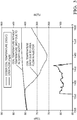
- Figure 2 shows the temperature profile of a coil of a urea injector over time with respect to a urea injection event (top) and the bottom plot shows the profile of urea flow from/through the injector.
- the injector may be cooled by coolant flowing through a coolant jacket. When no urea is flowing in the injector, the injector coil is heated to the temperature of the coolant flowing in the coolant jacket.
- the temperature of the supply of the reductant such as urea to the injector (i.e. incoming urea temperature) is usually at a different temperature (usually lower) than the temperature of the coil or coolant.
- Figure 3 compares the temperature profile of a injector which has become blocked (e.g, has a blocked nozzle) to one that is operating normally, during an operating cycle, i.e. injection event.
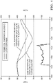
- Figure 4 compares the temperature profile of a injector coil for an injector operating normally and one which is partially blocked (during an injection cycle). As can be seen, there is a reduced cooling effect from the urea/reductant flow where there is a blocked nozzle.
- the temperature profile of the coil may be used to determine whether there is an impedance to flow.
- One measure may be determining the absolute temperature drop between two points such as the maximum temperature and the minimum temperature; this is shown in figure 5 for two cases, B) an injector operating normally and A) an injector with a (partially/fully) blocked nozzle.
- the absolute temperature drop for both cases subsequent to an injection event is shown by arrows B and A respectively.
- the change in temperature of an injector with time i.e. slope
- This method may be performed at selected or suitable time points, and is preferably performed from the point during an injection/activation cycle from maximum temperature to minimum temperature i.e. looking at the slope from the maximum temperature to the minimum temperature in an injection cycle as shown in figure 5 ; the slopes for unblocked or partially blocked injector temperature are shown by B' and A' respectively.
- a modelled coil temperature based on heat flow in and out of the coil may be used, and this compared to the measured coil temperature from the current in the injector.
Landscapes
- Engineering & Computer Science (AREA)
- Chemical & Material Sciences (AREA)
- Chemical Kinetics & Catalysis (AREA)
- Combustion & Propulsion (AREA)
- Mechanical Engineering (AREA)
- General Engineering & Computer Science (AREA)
- Health & Medical Sciences (AREA)
- Toxicology (AREA)
- Physics & Mathematics (AREA)
- Fluid Mechanics (AREA)
- General Physics & Mathematics (AREA)
- Exhaust Gas After Treatment (AREA)
Claims (9)
- Verfahren zum Analysieren eines Flusses von Reduktionsmittel durch einen Reduktionsmittelinjektor eines selektiven katalytischen Reduktionsmitteldosiersystems, wobei der Reduktionsmittelinjektor ausgebildet ist zum Einspritzen von flüssigem Reduktionsmittel in eine Abgasleitung, aufweisend:i) Vorsehen eines ersten Maßes oder Bestimmen eines ersten Temperaturprofils des Injektors vor einer Aktivierung des Injektors;ii) Aktivieren des Injektors;iii) Vorsehen eines zweiten Maßes oder Bestimmen eines zweiten Temperaturprofils des Injektors nach der Aktivierung;iv) Analysieren und Evaluieren der Änderungen der Durchflussmenge des Reduktionsmittels durch den Injektor infolge der Aktivierung durch Analysieren einer Änderung zwischen den ersten und zweiten Maßen oder Profilen der Temperaturen.
- Verfahren gemäß Anspruch 1, wobei in Schritt iv) die Durchflussmenge durch Vergleichen der Änderungen zwischen den ersten und zweiten Maßen oder Profilen der Temperaturen mit erwarteten Änderungen nachfolgend auf die Aktivierung analysiert wird.
- Verfahren gemäß den Ansprüchen 1 oder 2, wobei Schritt iv) ein Vergleichen des Profils des bestimmten Temperaturmaßes nachfolgend auf eine Aktivierung des Injektors mit erwarteten oder bekannten Profilen des Maßes der Injektortemperatur nachfolgend auf die Aktivierung aufweist.
- Verfahren gemäß den Ansprüchen 1 bis 3, wobei in Schritt iv) die Änderung zwischen den ersten und zweiten Maßen oder Profilen von Temperaturen die Änderung zwischen einem Zeitpunkt vor und einem Zeitpunkt nach der Aktivierung ist.
- Verfahren gemäß Anspruch 4, wobei die analysierte Änderung in Schritt iv) mit einer erwarteten Änderung nachfolgend auf die Aktivierung verglichen wird.
- Verfahren gemäß den Ansprüchen 1 bis 5, wobei aus den Schritten i) und iii) der Gradient des Maßes der Injektortemperatur in Bezug auf die Zeit bestimmt wird.
- Verfahren gemäß Anspruch 6, wobei in Schritt iv) der Gradient mit einem erwarteten Gradienten verglichen wird.
- Verfahren gemäß den Ansprüchen 1 bis 7, wobei der Injektor durch ein Kühlsystem gekühlt wird, das ein an den Injektor angrenzend fließendes Kühlfluid aufweist.
- Verfahren gemäß Anspruch 1 bis 8, wobei das Temperaturmaß des Injektors durch einen Temperatursensor angrenzend an den Injektor, eine Injektorspule, oder der Temperatur des Kühlmittels bestimmt wird.
Applications Claiming Priority (2)
| Application Number | Priority Date | Filing Date | Title |
|---|---|---|---|
| GBGB1521599.9A GB201521599D0 (en) | 2015-12-08 | 2015-12-08 | Method of determining operation of an SCR reductant doser |
| PCT/EP2016/079937 WO2017097776A1 (en) | 2015-12-08 | 2016-12-06 | Method of determining operation of an scr reductant doser |
Publications (2)
| Publication Number | Publication Date |
|---|---|
| EP3387231A1 EP3387231A1 (de) | 2018-10-17 |
| EP3387231B1 true EP3387231B1 (de) | 2020-03-11 |
Family
ID=55234562
Family Applications (1)
| Application Number | Title | Priority Date | Filing Date |
|---|---|---|---|
| EP16810285.3A Active EP3387231B1 (de) | 2015-12-08 | 2016-12-06 | Verfahren zur festlegung des betriebs eines scr-reduktionsmitteldosierspenders |
Country Status (5)
| Country | Link |
|---|---|
| US (1) | US10711675B2 (de) |
| EP (1) | EP3387231B1 (de) |
| CN (1) | CN108699940B (de) |
| GB (1) | GB201521599D0 (de) |
| WO (1) | WO2017097776A1 (de) |
Families Citing this family (3)
| Publication number | Priority date | Publication date | Assignee | Title |
|---|---|---|---|---|
| US10415450B2 (en) * | 2017-10-31 | 2019-09-17 | Cummins Emission Solutions Inc. | Systems and methods for reductant dosing including on-time correction for switching delays |
| FR3106852B1 (fr) | 2020-02-04 | 2021-12-24 | Vitesco Technologies | Détermination d’une température de bobine d’injecteur à solénoïde |
| EP4098859B1 (de) * | 2021-05-31 | 2024-06-26 | Marelli Europe S.p.A. | Verfahren zur schätzung der temperatur eines elektromagnetischen aktuators |
Family Cites Families (17)
| Publication number | Priority date | Publication date | Assignee | Title |
|---|---|---|---|---|
| JP3855781B2 (ja) * | 2002-01-29 | 2006-12-13 | トヨタ自動車株式会社 | 還元剤供給装置 |
| JP4906525B2 (ja) * | 2007-01-26 | 2012-03-28 | ボッシュ株式会社 | 還元剤噴射弁の詰まり判定装置及び還元剤噴射弁の詰まり判定方法 |
| US7799289B2 (en) * | 2007-07-31 | 2010-09-21 | Caterpillar Inc | Exhaust treatment system with NO2 control |
| JP5534602B2 (ja) * | 2009-11-06 | 2014-07-02 | ボッシュ株式会社 | 還元剤噴射弁の異常検出装置及び異常検出方法 |
| US8671666B2 (en) * | 2010-03-11 | 2014-03-18 | Cummins Inc. | System and apparatus for enhancing exhaust aftertreatment startup emissions control |
| US8733083B2 (en) * | 2010-04-26 | 2014-05-27 | Cummins Filtration Ip, Inc. | SCR catalyst ammonia surface coverage estimation and control |
| US8793977B2 (en) * | 2010-07-09 | 2014-08-05 | Paccar Inc | Injector control for a selective catalytic reduction system |
| US8516800B2 (en) * | 2010-12-22 | 2013-08-27 | Caterpillar Inc. | System and method for introducing a reductant agent |
| DE102012200917B4 (de) | 2012-01-23 | 2023-06-29 | Robert Bosch Gmbh | Verfahren zum Erkennen einer Verstopfung eines Dosierventils eines SCR-Katalysatorsystems |
| US20140127097A1 (en) * | 2012-11-02 | 2014-05-08 | International Engine Intellectual Property Company, Llc | Ammonia flow control |
| US9261006B2 (en) | 2013-03-01 | 2016-02-16 | Cummins Ip, Inc. | Apparatus, method and system for diagnosing reductant deposits in an exhaust aftertreatment system |
| KR101438630B1 (ko) * | 2013-04-15 | 2014-09-05 | 현대자동차 주식회사 | 선택적 촉매 환원(scr) 시스템의 우레아 분사 노즐의 막힘 방지 방법 |
| CN103277175B (zh) * | 2013-06-08 | 2015-06-17 | 潍柴动力股份有限公司 | 一种还原剂喷嘴的状态检测方法及装置、催化还原系统 |
| US9217350B2 (en) * | 2013-11-13 | 2015-12-22 | Ford Global Technologies, Llc | Method and system for reductant injector degradation |
| US9194269B2 (en) * | 2014-04-24 | 2015-11-24 | Fca Us Llc | Reductant injector temperature model based on coil resistance |
| US10352217B2 (en) * | 2015-04-10 | 2019-07-16 | Volvo Truck Corporation | Method for controlling the injection of reductant for an exhaust after treatment unit |
| US10473020B2 (en) * | 2016-07-25 | 2019-11-12 | Ford Global Technologies, Llc | Method and system for exhaust aftertreatment |
-
2015
- 2015-12-08 GB GBGB1521599.9A patent/GB201521599D0/en not_active Ceased
-
2016
- 2016-12-06 US US15/781,872 patent/US10711675B2/en active Active
- 2016-12-06 WO PCT/EP2016/079937 patent/WO2017097776A1/en not_active Ceased
- 2016-12-06 CN CN201680071352.3A patent/CN108699940B/zh active Active
- 2016-12-06 EP EP16810285.3A patent/EP3387231B1/de active Active
Non-Patent Citations (1)
| Title |
|---|
| None * |
Also Published As
| Publication number | Publication date |
|---|---|
| US10711675B2 (en) | 2020-07-14 |
| US20180363529A1 (en) | 2018-12-20 |
| WO2017097776A1 (en) | 2017-06-15 |
| EP3387231A1 (de) | 2018-10-17 |
| CN108699940A (zh) | 2018-10-23 |
| CN108699940B (zh) | 2020-05-15 |
| GB201521599D0 (en) | 2016-01-20 |
Similar Documents
| Publication | Publication Date | Title |
|---|---|---|
| DE19933798C2 (de) | Vorrichtung und Verfahren zur Abgasnachbehandlung bei einer Brennkraftmaschine | |
| US8720189B2 (en) | Apparatus and method for onboard performance monitoring of oxidation catalyst | |
| CN103764964B (zh) | 具有磁通桥和磁通间隔的电磁控制式喷射器 | |
| EP2578861B1 (de) | System für selektive katalytische reduktion | |
| CN102454460A (zh) | 用于对机动车辆上的后处理系统进行氨喷射质量测量的方法 | |
| US10711675B2 (en) | Method of determining operation of an SCR reductant doser | |
| CN104343509B (zh) | 柴油机排气流体注射器的控制设备 | |
| US10859446B2 (en) | Temperature measuring device | |
| KR20150024356A (ko) | 차량용 배기 가스 후처리 시스템에서 유압 누출-방지성을 검사하기 위한 방법 및 장치 | |
| US20130276429A1 (en) | Method for diagnosing a metering valve and device for carrying out the method | |
| EP2573343A1 (de) | Kompetenzdiagnosesystem für einen harnstofftemperatursensor | |
| Ferrari et al. | Design and rapid prototyping of a closed-loop control strategy of the injected mass for the reduction of CO2, combustion noise and pollutant emissions in diesel engines | |
| US20130340412A1 (en) | Exhaust purifier of an internal combustion engine | |
| US10775223B2 (en) | Method for determining deviations in quantity in the case of a fluidic metering system | |
| US10473014B2 (en) | Low pressure atomizing injector | |
| JP2009197741A (ja) | 内燃機関の排気浄化システム | |
| US10995749B2 (en) | Method for monitoring the volumetric flow of a metering valve of a fluidic metering system of an internal combustion engine, in particular of a motor vehicle | |
| US20140234174A1 (en) | Exhaust gas purification apparatus for an internal combustion engine | |
| US8688402B2 (en) | Systems and methods for estimating a temperature of a fluid injector used in a hot environment | |
| US9488086B2 (en) | Low pressure atomizing injector | |
| KR20190038649A (ko) | 차단된 압력 라인의 검출 방법 | |
| CN103899390A (zh) | 氨泄漏减少 | |
| EP3921521B1 (de) | Steuersystem für ein dieselabgasfluidzufuhrsystem | |
| CN103806992A (zh) | 氨流量控制 | |
| WO2016173774A1 (en) | Urea dosing method for vehicle exhaust systems |
Legal Events
| Date | Code | Title | Description |
|---|---|---|---|
| STAA | Information on the status of an ep patent application or granted ep patent |
Free format text: STATUS: UNKNOWN |
|
| STAA | Information on the status of an ep patent application or granted ep patent |
Free format text: STATUS: THE INTERNATIONAL PUBLICATION HAS BEEN MADE |
|
| PUAI | Public reference made under article 153(3) epc to a published international application that has entered the european phase |
Free format text: ORIGINAL CODE: 0009012 |
|
| STAA | Information on the status of an ep patent application or granted ep patent |
Free format text: STATUS: REQUEST FOR EXAMINATION WAS MADE |
|
| 17P | Request for examination filed |
Effective date: 20180709 |
|
| AK | Designated contracting states |
Kind code of ref document: A1 Designated state(s): AL AT BE BG CH CY CZ DE DK EE ES FI FR GB GR HR HU IE IS IT LI LT LU LV MC MK MT NL NO PL PT RO RS SE SI SK SM TR |
|
| AX | Request for extension of the european patent |
Extension state: BA ME |
|
| DAV | Request for validation of the european patent (deleted) | ||
| DAX | Request for extension of the european patent (deleted) | ||
| STAA | Information on the status of an ep patent application or granted ep patent |
Free format text: STATUS: EXAMINATION IS IN PROGRESS |
|
| 17Q | First examination report despatched |
Effective date: 20190702 |
|
| GRAP | Despatch of communication of intention to grant a patent |
Free format text: ORIGINAL CODE: EPIDOSNIGR1 |
|
| STAA | Information on the status of an ep patent application or granted ep patent |
Free format text: STATUS: GRANT OF PATENT IS INTENDED |
|
| INTG | Intention to grant announced |
Effective date: 20191119 |
|
| GRAS | Grant fee paid |
Free format text: ORIGINAL CODE: EPIDOSNIGR3 |
|
| GRAA | (expected) grant |
Free format text: ORIGINAL CODE: 0009210 |
|
| STAA | Information on the status of an ep patent application or granted ep patent |
Free format text: STATUS: THE PATENT HAS BEEN GRANTED |
|
| AK | Designated contracting states |
Kind code of ref document: B1 Designated state(s): AL AT BE BG CH CY CZ DE DK EE ES FI FR GB GR HR HU IE IS IT LI LT LU LV MC MK MT NL NO PL PT RO RS SE SI SK SM TR |
|
| REG | Reference to a national code |
Ref country code: GB Ref legal event code: FG4D |
|
| REG | Reference to a national code |
Ref country code: CH Ref legal event code: EP |
|
| REG | Reference to a national code |
Ref country code: AT Ref legal event code: REF Ref document number: 1243401 Country of ref document: AT Kind code of ref document: T Effective date: 20200315 |
|
| REG | Reference to a national code |
Ref country code: IE Ref legal event code: FG4D |
|
| REG | Reference to a national code |
Ref country code: DE Ref legal event code: R096 Ref document number: 602016031691 Country of ref document: DE |
|
| PG25 | Lapsed in a contracting state [announced via postgrant information from national office to epo] |
Ref country code: NO Free format text: LAPSE BECAUSE OF FAILURE TO SUBMIT A TRANSLATION OF THE DESCRIPTION OR TO PAY THE FEE WITHIN THE PRESCRIBED TIME-LIMIT Effective date: 20200611 Ref country code: FI Free format text: LAPSE BECAUSE OF FAILURE TO SUBMIT A TRANSLATION OF THE DESCRIPTION OR TO PAY THE FEE WITHIN THE PRESCRIBED TIME-LIMIT Effective date: 20200311 Ref country code: RS Free format text: LAPSE BECAUSE OF FAILURE TO SUBMIT A TRANSLATION OF THE DESCRIPTION OR TO PAY THE FEE WITHIN THE PRESCRIBED TIME-LIMIT Effective date: 20200311 |
|
| REG | Reference to a national code |
Ref country code: NL Ref legal event code: MP Effective date: 20200311 |
|
| PG25 | Lapsed in a contracting state [announced via postgrant information from national office to epo] |
Ref country code: HR Free format text: LAPSE BECAUSE OF FAILURE TO SUBMIT A TRANSLATION OF THE DESCRIPTION OR TO PAY THE FEE WITHIN THE PRESCRIBED TIME-LIMIT Effective date: 20200311 Ref country code: GR Free format text: LAPSE BECAUSE OF FAILURE TO SUBMIT A TRANSLATION OF THE DESCRIPTION OR TO PAY THE FEE WITHIN THE PRESCRIBED TIME-LIMIT Effective date: 20200612 Ref country code: BG Free format text: LAPSE BECAUSE OF FAILURE TO SUBMIT A TRANSLATION OF THE DESCRIPTION OR TO PAY THE FEE WITHIN THE PRESCRIBED TIME-LIMIT Effective date: 20200611 Ref country code: LV Free format text: LAPSE BECAUSE OF FAILURE TO SUBMIT A TRANSLATION OF THE DESCRIPTION OR TO PAY THE FEE WITHIN THE PRESCRIBED TIME-LIMIT Effective date: 20200311 Ref country code: SE Free format text: LAPSE BECAUSE OF FAILURE TO SUBMIT A TRANSLATION OF THE DESCRIPTION OR TO PAY THE FEE WITHIN THE PRESCRIBED TIME-LIMIT Effective date: 20200311 |
|
| REG | Reference to a national code |
Ref country code: LT Ref legal event code: MG4D |
|
| PG25 | Lapsed in a contracting state [announced via postgrant information from national office to epo] |
Ref country code: NL Free format text: LAPSE BECAUSE OF FAILURE TO SUBMIT A TRANSLATION OF THE DESCRIPTION OR TO PAY THE FEE WITHIN THE PRESCRIBED TIME-LIMIT Effective date: 20200311 |
|
| PG25 | Lapsed in a contracting state [announced via postgrant information from national office to epo] |
Ref country code: LT Free format text: LAPSE BECAUSE OF FAILURE TO SUBMIT A TRANSLATION OF THE DESCRIPTION OR TO PAY THE FEE WITHIN THE PRESCRIBED TIME-LIMIT Effective date: 20200311 Ref country code: CZ Free format text: LAPSE BECAUSE OF FAILURE TO SUBMIT A TRANSLATION OF THE DESCRIPTION OR TO PAY THE FEE WITHIN THE PRESCRIBED TIME-LIMIT Effective date: 20200311 Ref country code: EE Free format text: LAPSE BECAUSE OF FAILURE TO SUBMIT A TRANSLATION OF THE DESCRIPTION OR TO PAY THE FEE WITHIN THE PRESCRIBED TIME-LIMIT Effective date: 20200311 Ref country code: PT Free format text: LAPSE BECAUSE OF FAILURE TO SUBMIT A TRANSLATION OF THE DESCRIPTION OR TO PAY THE FEE WITHIN THE PRESCRIBED TIME-LIMIT Effective date: 20200805 Ref country code: SM Free format text: LAPSE BECAUSE OF FAILURE TO SUBMIT A TRANSLATION OF THE DESCRIPTION OR TO PAY THE FEE WITHIN THE PRESCRIBED TIME-LIMIT Effective date: 20200311 Ref country code: IS Free format text: LAPSE BECAUSE OF FAILURE TO SUBMIT A TRANSLATION OF THE DESCRIPTION OR TO PAY THE FEE WITHIN THE PRESCRIBED TIME-LIMIT Effective date: 20200711 Ref country code: SK Free format text: LAPSE BECAUSE OF FAILURE TO SUBMIT A TRANSLATION OF THE DESCRIPTION OR TO PAY THE FEE WITHIN THE PRESCRIBED TIME-LIMIT Effective date: 20200311 Ref country code: RO Free format text: LAPSE BECAUSE OF FAILURE TO SUBMIT A TRANSLATION OF THE DESCRIPTION OR TO PAY THE FEE WITHIN THE PRESCRIBED TIME-LIMIT Effective date: 20200311 |
|
| REG | Reference to a national code |
Ref country code: AT Ref legal event code: MK05 Ref document number: 1243401 Country of ref document: AT Kind code of ref document: T Effective date: 20200311 |
|
| REG | Reference to a national code |
Ref country code: DE Ref legal event code: R097 Ref document number: 602016031691 Country of ref document: DE |
|
| PLBE | No opposition filed within time limit |
Free format text: ORIGINAL CODE: 0009261 |
|
| STAA | Information on the status of an ep patent application or granted ep patent |
Free format text: STATUS: NO OPPOSITION FILED WITHIN TIME LIMIT |
|
| PG25 | Lapsed in a contracting state [announced via postgrant information from national office to epo] |
Ref country code: ES Free format text: LAPSE BECAUSE OF FAILURE TO SUBMIT A TRANSLATION OF THE DESCRIPTION OR TO PAY THE FEE WITHIN THE PRESCRIBED TIME-LIMIT Effective date: 20200311 Ref country code: IT Free format text: LAPSE BECAUSE OF FAILURE TO SUBMIT A TRANSLATION OF THE DESCRIPTION OR TO PAY THE FEE WITHIN THE PRESCRIBED TIME-LIMIT Effective date: 20200311 Ref country code: DK Free format text: LAPSE BECAUSE OF FAILURE TO SUBMIT A TRANSLATION OF THE DESCRIPTION OR TO PAY THE FEE WITHIN THE PRESCRIBED TIME-LIMIT Effective date: 20200311 Ref country code: AT Free format text: LAPSE BECAUSE OF FAILURE TO SUBMIT A TRANSLATION OF THE DESCRIPTION OR TO PAY THE FEE WITHIN THE PRESCRIBED TIME-LIMIT Effective date: 20200311 |
|
| 26N | No opposition filed |
Effective date: 20201214 |
|
| PG25 | Lapsed in a contracting state [announced via postgrant information from national office to epo] |
Ref country code: SI Free format text: LAPSE BECAUSE OF FAILURE TO SUBMIT A TRANSLATION OF THE DESCRIPTION OR TO PAY THE FEE WITHIN THE PRESCRIBED TIME-LIMIT Effective date: 20200311 Ref country code: PL Free format text: LAPSE BECAUSE OF FAILURE TO SUBMIT A TRANSLATION OF THE DESCRIPTION OR TO PAY THE FEE WITHIN THE PRESCRIBED TIME-LIMIT Effective date: 20200311 |
|
| REG | Reference to a national code |
Ref country code: CH Ref legal event code: PL |
|
| PG25 | Lapsed in a contracting state [announced via postgrant information from national office to epo] |
Ref country code: MC Free format text: LAPSE BECAUSE OF FAILURE TO SUBMIT A TRANSLATION OF THE DESCRIPTION OR TO PAY THE FEE WITHIN THE PRESCRIBED TIME-LIMIT Effective date: 20200311 |
|
| REG | Reference to a national code |
Ref country code: BE Ref legal event code: MM Effective date: 20201231 |
|
| PG25 | Lapsed in a contracting state [announced via postgrant information from national office to epo] |
Ref country code: IE Free format text: LAPSE BECAUSE OF NON-PAYMENT OF DUE FEES Effective date: 20201206 Ref country code: LU Free format text: LAPSE BECAUSE OF NON-PAYMENT OF DUE FEES Effective date: 20201206 |
|
| PG25 | Lapsed in a contracting state [announced via postgrant information from national office to epo] |
Ref country code: LI Free format text: LAPSE BECAUSE OF NON-PAYMENT OF DUE FEES Effective date: 20201231 Ref country code: CH Free format text: LAPSE BECAUSE OF NON-PAYMENT OF DUE FEES Effective date: 20201231 |
|
| PG25 | Lapsed in a contracting state [announced via postgrant information from national office to epo] |
Ref country code: TR Free format text: LAPSE BECAUSE OF FAILURE TO SUBMIT A TRANSLATION OF THE DESCRIPTION OR TO PAY THE FEE WITHIN THE PRESCRIBED TIME-LIMIT Effective date: 20200311 Ref country code: MT Free format text: LAPSE BECAUSE OF FAILURE TO SUBMIT A TRANSLATION OF THE DESCRIPTION OR TO PAY THE FEE WITHIN THE PRESCRIBED TIME-LIMIT Effective date: 20200311 Ref country code: CY Free format text: LAPSE BECAUSE OF FAILURE TO SUBMIT A TRANSLATION OF THE DESCRIPTION OR TO PAY THE FEE WITHIN THE PRESCRIBED TIME-LIMIT Effective date: 20200311 |
|
| PG25 | Lapsed in a contracting state [announced via postgrant information from national office to epo] |
Ref country code: MK Free format text: LAPSE BECAUSE OF FAILURE TO SUBMIT A TRANSLATION OF THE DESCRIPTION OR TO PAY THE FEE WITHIN THE PRESCRIBED TIME-LIMIT Effective date: 20200311 Ref country code: AL Free format text: LAPSE BECAUSE OF FAILURE TO SUBMIT A TRANSLATION OF THE DESCRIPTION OR TO PAY THE FEE WITHIN THE PRESCRIBED TIME-LIMIT Effective date: 20200311 |
|
| PG25 | Lapsed in a contracting state [announced via postgrant information from national office to epo] |
Ref country code: BE Free format text: LAPSE BECAUSE OF NON-PAYMENT OF DUE FEES Effective date: 20201231 |
|
| P01 | Opt-out of the competence of the unified patent court (upc) registered |
Effective date: 20230327 |
|
| REG | Reference to a national code |
Ref country code: DE Ref legal event code: R081 Ref document number: 602016031691 Country of ref document: DE Owner name: PHINIA DELPHI LUXEMBOURG SARL, LU Free format text: FORMER OWNER: DELPHI TECHNOLOGIES IP LIMITED, SAINT MICHAEL, BB |
|
| REG | Reference to a national code |
Ref country code: GB Ref legal event code: 732E Free format text: REGISTERED BETWEEN 20240725 AND 20240731 |
|
| PGFP | Annual fee paid to national office [announced via postgrant information from national office to epo] |
Ref country code: DE Payment date: 20251118 Year of fee payment: 10 |
|
| PGFP | Annual fee paid to national office [announced via postgrant information from national office to epo] |
Ref country code: GB Payment date: 20251113 Year of fee payment: 10 |
|
| PGFP | Annual fee paid to national office [announced via postgrant information from national office to epo] |
Ref country code: FR Payment date: 20251111 Year of fee payment: 10 |