EP1196246B1 - Freistrahlzentrifuge, insbesondere zur reinigung des schmieröls einer brennkraftmaschine - Google Patents
Freistrahlzentrifuge, insbesondere zur reinigung des schmieröls einer brennkraftmaschine Download PDFInfo
- Publication number
- EP1196246B1 EP1196246B1 EP00936891A EP00936891A EP1196246B1 EP 1196246 B1 EP1196246 B1 EP 1196246B1 EP 00936891 A EP00936891 A EP 00936891A EP 00936891 A EP00936891 A EP 00936891A EP 1196246 B1 EP1196246 B1 EP 1196246B1
- Authority
- EP
- European Patent Office
- Prior art keywords
- rotor
- centrifuge
- bearing
- free
- housing
- Prior art date
- Legal status (The legal status is an assumption and is not a legal conclusion. Google has not performed a legal analysis and makes no representation as to the accuracy of the status listed.)
- Expired - Lifetime
Links
Images

Classifications
-
- B—PERFORMING OPERATIONS; TRANSPORTING
- B04—CENTRIFUGAL APPARATUS OR MACHINES FOR CARRYING-OUT PHYSICAL OR CHEMICAL PROCESSES
- B04B—CENTRIFUGES
- B04B9/00—Drives specially designed for centrifuges; Arrangement or disposition of transmission gearing; Suspending or balancing rotary bowls
- B04B9/08—Arrangement or disposition of transmission gearing ; Couplings; Brakes
-
- B—PERFORMING OPERATIONS; TRANSPORTING
- B04—CENTRIFUGAL APPARATUS OR MACHINES FOR CARRYING-OUT PHYSICAL OR CHEMICAL PROCESSES
- B04B—CENTRIFUGES
- B04B5/00—Other centrifuges
- B04B5/005—Centrifugal separators or filters for fluid circulation systems, e.g. for lubricant oil circulation systems
Definitions
- the invention relates to a free-jet centrifuge, the z. B. for cleaning lubricating oil can be used in an internal combustion engine, according to the preamble of claim 1.
- the valve 40 closes, so that the Passage of the oil is prevented in the centrifuge rotor. Due to the bearing friction the plain bearing then comes to a standstill. The bearing friction is thereby increases that the centrifuge rotor on the lower axial stop in the housing lowers, whereby the bearing surface of the sliding bearing is increased.
- GB-A-2 322 315 shows a free-jet centrifuge according to the preamble of the claim 1, in which only after switching off the liquid supply by lifting the Equilibrium of the axial forces braking the rotos by applying the rotor takes place at axial stops.
- the invention has for its object to provide a centrifuge with a rotor, which at the same time by realization of high speeds a good centrifuging achieved result and after switching off has short follow-up times. This task is solved by the patent claim 1.
- the free-jet centrifuge according to the invention consists in a known manner of a Rotor with an inlet and at least one drive nozzle, the same outlet is.
- the deposition surface for the deposited suspended matter of the fluid can z. B. be formed by the rotor shell.
- the housing serves to shield the Rotor over the environment. This is necessary as the jet of drive nozzles must be caught.
- housing within the meaning of the invention is any type of shuttering, that protects the environment, to understand. It does not have a separate housing be provided for the centrifuge.
- the centrifuge z. B. in cavities of an internal combustion engine, which to the oil circuit belongs.
- the storage of the centrifuge rotor in the housing allows the same time Rotation and ensures a limitation of the axial play of the rotor.
- a force source is provided in the free-jet centrifuge which on the one hand fixed in the housing of the centrifuge and their power development on the other hand acts on the rotor.
- This power source can, for. B. from a coil spring consist whose ends are supported respectively on the rotor bearing and in the housing, with the spring under tension.
- the force of the power source works against the axial forces that occur during rotor operation.
- This provides a balance of power between the power source and the in-service Rotor on.
- the rotor moves within its axial range of motion in the Position of the balance of forces, where it does not connect to any of the axial stops stands. This is a low-friction operation of the centrifuge at high speeds possible.
- the power source simultaneously acts as a buffer for pressure fluctuations, which shift the balance of power, but not to a rubbing of the rotor on one of the axial stops.
- the power source pushes the rotor to one of the axial stops. This creates a braking torque, which the Rotor can decelerate to a standstill. A long after-run is prevented whereby z. B. idle the engine no noise of the centrifuge can be heard.
- the power source also has the positive effect that the bearing partners be kept under pretension. This is when turning the centrifuge prevents beating of the bearing due to their bearing clearance, which also can cause unpleasant noises. For the rest, this is the danger circumvented that damage caused by the bearing impact, the storage life shorten. This is especially when using bearings for storage of the rotor necessary. But bearings also benefit from the shortened ones Follow-up times. In this operating condition, namely, the lubrication of the bearing not completely guaranteed due to the low oil pressure. A long time Tracking would therefore lead to increased bearing wear.
- the spring If, as described, the spring is used as a power source, then it unfolds a force which is dependent on the spring characteristic of the axial travel of the rotor in the housing.
- This is a particularly simple embodiment that provides a self-regulating system for the free-jet centrifuge.
- a condition is that the spring is designed such that the resulting amount of spring force is always less than or equal to the resulting by the rotor operation within the intended operating range amount of axial force.
- the operating range is defined by the speed of the rotor and the oil pressure. Only when the operating range is left downwards, the spring force exceeds the axial force of the rotor, so that it is pressed against one of its axial stops and braked.
- the run-up behavior of the rotor is ensured by the fact that with an increase in the oil pressure, this can solve again from the axial stop and is set in rotation. He then moves axially so long against the spring force until the described balance of forces has set again.
- This self-regulating structure can of course also with other sources of power, eg. B. reach a pneumatic cylinder.
- the invention consists in providing the power source with a foreign operation.
- the force introduction of the power source can be controlled by any control mechanisms.
- the power source can, for. B. consist of a hydraulic cylinder, which is controlled externally.
- an electromechanical drive, for. B. a motor-gear combination conceivable.
- the pressure cans frequently used in the motor vehicle sector also provide a sensible solution to the externally actuated drive of the power source.
- the centrifuge With the help of external operation, the centrifuge can be braked down from any operating condition by activating the power source against the axial stop is pressed. Meaningful operating conditions in which a deceleration the rotor makes sense, on the one hand in the idle state already described, on the other hand, in the event that an insufficient supply of Internal combustion engine with lubricating oil threatens.
- the centrifuge are turned off, so that the operation of the Centrifuge necessary secondary flow of oil directly available for lubrication stands. This function is otherwise through appropriate valves in the oil circuit guaranteed, which can be dispensed with in the described solution. hereby This results in an additional saving effect, which leads to a higher economic efficiency the solution leads or the extra work for the externally operated power source outweighs.
- a particularly favorable embodiment results in a free-jet centrifuge, as Storage on one side has a plain bearing, which at the same time the inlet is. The lubrication is then carried out by the liquid introduced.
- a second Bearing is a rolling bearing used, which leads to extremely low friction losses leads. This is completely outside of the liquid stream to be centrifuged appropriate.
- the power source is between a support in the housing and clamped the rolling bearing, so that the rolling bearing is axially displaceable. With the Displacement of the bearing is moved simultaneously the centrifuge rotor. These Axial movement is permitted in plain bearings.
- the rolling bearing z. B. with his Inner ring attached to the rotor while the power source on the outer ring attacks. This is independent of the operating condition of the centrifuge a clearance in the rolling bearing prevented.
- An alternative way to brake the rotor is the realization a thrust reverser. This is achieved by actuating nozzles on the centrifuge rotor, which allow a drive opposite to the normal direction of rotation.
- the nozzle heads of the centrifuge rotor can be made rotatable be so that the thrust reversal by rotation of the nozzles reach by 180 ° leaves.
- Another possibility is the attachment of additional brake nozzles whose Spray direction is opposite to that of the drive nozzles.
- the activation of the Nozzles can be controlled by the pressure present in the rotor.
- a friction surface pair is provided, wherein one of the friction partners in Housing and the other is fixed to the rotor.
- This friction surface pairing can as Brake can be used.
- An advantageous possibility is the friction partners ring-shaped and in the area of one of the rotor lid surfaces and the housing accommodate. The function of this friction surface pair is with the already described Axial stop comparable to storage. The friction surface pair replaced exactly this axial stop in the camp, namely the one which the axial Movement tendency of the rotor is opposite in operation. Outside the intended Operating range of the rotor lowers this on the friction pairing and is thereby slowed down.
- This process can be performed by a power source according to one of claims 1 to 5 are supported.
- the effect can be synonymous achieve solely by acting on the centrifuge rotor gravity.
- the rotor can be decelerated from any operating condition to a standstill. This gives rise to a possibility of the flow through the centrifuge to reduce a minimum, since the volume flow at the nozzles only at high Speeds due to the resulting dynamic pressures in the interior of the centrifuge significant amounts reached. At standstill, the volume flow through the narrow Nozzle bore negligible. This means that valves for actuation and Control of the centrifuge can be completely saved, with the leakage current is accepted by the nozzle opening at standstill of the rotor. By Saving the control valves, the economics of the centrifuge can be clearly increase.
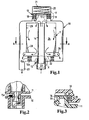
- a free-jet centrifuge according to FIG. 1 has a housing 10 in which a rotor 11 is rotatably mounted using a sliding bearing 12 and a rolling bearing 13.
- the sliding bearing 12 allows axial displacement of the rotor, with a central tube 14 immersed in this camp.
- An axial limitation in the direction of the sliding bearing is ensured by friction surfaces 15a, 15b.
- the rolling bearing 13 is fixedly connected to a nozzle 16 on the centrifuge rotor. Of the Spigot extends into an inner ring 17 of the bearing.
- the outer ring 19 of the rolling bearing is radially fixed in a receptacle 18 in the housing. In the axial direction is a displacement of the rolling bearing 13 is possible, this by a on a Outer ring 19 of the rolling bearing acting coil spring 20 is limited.
- the feather has an abutment in a support 21 in the housing.
- the rotor 11 by the spring 20 with the friction surface 15 a, which at a Cover surface 22 of the rotor is mounted on the housed in the housing Friction surface 15b pressed. If the oil pressure in an inlet 23 increases, the rotor acts like a hydraulic cylinder and rises in the sliding bearing 12 as soon as the oil pressure resulting force exceeds the spring force.
- the oil passes through the central tube 14 in a separation chamber 24, from there into nozzle channels 25 and is driven by drive nozzles 26 injected into the housing, from where it drains through an outlet 27.
- the Drive nozzles cause the rotor 11 to rotate, causing the oil to be in the oil Suspended matter 28 are deposited on the deposition surfaces 29 of the rotor.
- this axial position is located above the through the friction surfaces 15a and 15b formed axial stop.
- the axial force on the rotor becomes mainly determined by the voltage applied to the inlet 23 oil pressure. It sinks below a certain one Value that defines the lower limit of the operating range leads to the Spring force of the spring 20 to a lowering of the rotor such that the friction surfaces 15a, 15b and the rotor is braked to a standstill.
- FIG. 2 shows an alternative possibility of arranging friction surface pairs.
- the Reib lakefish must not necessarily made especially for this on the Parts of the centrifuge attached materials exist. It is also possible to use the material of housing 10 and rotor 11 itself. Furthermore you can Friction surfaces 15 c, 15 d are housed in the region of the sliding bearing. These form in the manner described, the axial stop, wherein the friction surfaces to a sudden Increase in friction in the bearing lead, as soon as the axial stop in the rotor with the friction surfaces come into contact.
- Figure 3 shows a variant for the rolling bearing of the rotor without an additional Power source.
- the rolling bearing 19 is fixedly mounted in the housing 10.
- the nozzle 16 of the Rotor 11 is axially displaceable in the inner ring 17 of the rolling bearing, wherein a shoulder 30th limits the axial movement.
- According to the principle with power source acts on The rotor 11 acting gravity as restoring force, which in described Mode is in equilibrium with the axial forces acting on the rotor.
- FIG. 4 shows a centrifuge consisting of the rotor 11 and the housing 10, shown.
- the inlet 23 and the outlet 27 can be seen.
- the rotor is equipped with a brake nozzle 31.
- the nozzle channels 25 are equipped with valves 32 which are provided with a pressure actuator 33. The pressure actuation switches the valves such that below the operating pressure range the brake nozzle 31 is released and within the operating pressure range the drive nozzle 26 is unlocked. If the pressure drops z. B. at idle Motor so far that the operating pressure is exited, a switching of the Valves to the fact that the brake nozzle is activated.
- FIG. 5 shows a centrifuge in the illustration corresponding to FIG. 4 Brake nozzle 31, however, a brake band 34 is provided which by a schematic illustrated pneumatic cylinder 35, the z. B. also by a vacuum box can be formed, is externally operated.
- a brake band 34 is pressed against an outer wall 36 of the rotor. This creates a braking torque which depends on the pneumatic cylinder applied pressure is.
- the pneumatic cylinder is activated by an actuating valve 37, which communicates with a pressure accumulator 38.
- a control unit 39 is provided, depending on the parameters such as speed n and oil pressure p of a motor 40, the switching signal s to an actuating valve 37 passes.
- the Stop the centrifuge from any operating condition.
- the drive nozzle 26 The stationary centrifuge acts as a throttle, so that a valve for the supply the centrifuge with oil is not necessary.
Landscapes
- Centrifugal Separators (AREA)
- Lubrication Details And Ventilation Of Internal Combustion Engines (AREA)
- Lubricants (AREA)
- Braking Arrangements (AREA)
- Sliding-Contact Bearings (AREA)
Description
Die Erfindung besteht darin, die Kraftquelle mit einer Fremdbetätigung zu versehen. Dadurch läßt sich die Krafteinleitung der Kraftquelle durch beliebige Regelmechanismen steuern. Die Kraftquelle kann z. B. aus einem Hydraulikzylinder bestehen, der fremd angesteuert wird. Alternativ ist ein elektromechanischer Antrieb, z. B. eine Motor-Getriebe-Kombination denkbar. Auch die im Kraftfahrzeugbereich häufig zur Anwendung kommenden Druckdosen ergeben eine sinnvolle Lösung zum fremdbetätigten Antrieb der Kraftquelle.
- Figur 1
- den Querschnitt durch eine Freistrahlzentrifuge mit Gehäuse und Rotor,
- Figur 2
- das Detail X aus Figur 1,
- Figur 3
- das Detail Y aus Figur 1,
- Figur 4
- den schematischen Querschnitt einer Zentrifuge, wobei die Darstellung der Perspektive A - A gemäß Figur 1 folgt und eine zusätzliche Bremsdüse am Umfang vorgesehen ist und
- Figur 5
- den Querschnitt einer Zentrifuge mit Bremsband, welches unter Auswertung diverser Motorparameter fremdbetätigt ist.
Claims (5)
- Freistrahlzentrifuge, insbesondere zur Reinigung des Schmieröls einer Brennkraftmaschine, welcheaufweist, wobei eine ortsfeste, fremdbetätigte Kraftquelle an der Freistrahlzentrifuge vorgesehen ist, deren Kraftentfaltung auf den Rotor in axialer Richtung den durch den Rotorbetrieb entstehenden Axialkräften entgegengerichtet ist, dadurch gekennzeichnet, dass die Kraftquelle so dimensioniert ist, dass die Zentrifuge aus jedem Betriebszustand herunter gebremst werden kann, indem sie durch Aktivierung der Kraftquelle gegen die Axialspielbegrenzung gedrückt wird.einen Rotor (11) mit einem Einlass (23) und mindestens einer Antriebsdüse (26) als Auslass und einer Ablagerungsfläche (29) im Inneren des Rotors,ein Gehäuse (10) zur Abschirmung des Rotors gegenüber der Umgebung,Lagerungsmittel zur drehbaren Lagerung und zur Begrenzung des Axialspiels des Rotors (11) im Gehäuse (10)
- Freistrahlzentrifuge nach Anspruch 1, wobei eines der Lagerungsmittel aus einem Gleitlager (12) besteht, welches gleichzeitig den Einlass (23) bildet und ein anderes Lagerungsmittel aus einem Wälzlager (13) besteht, dadurch gekennzeichnet, dass die Kraftquelle zwischen einer Abstützung (21) im Gehäuse und dem Wälzlager eingespannt ist, wobei das Wälzlager axial verschiebbar in einer Aufnahme (18) im Gehäuse montiert ist.
- Freistrahlzentrifuge nach einem der vorherigen Ansprüche, dadurch gekennzeichnet, dass die Kraftquelle eine Schraubenfeder (20) ist.
- Freistrahlzentrifuge nach einem der vorherigen Ansprüche, dadurch gekennzeichnet, dass außerhalb der Lagerungsmittel ein Reibflächenpaar (15a, 15b) vorgesehen ist, wobei einer der Reibpartner im Gehäuse und der andere am Rotor fixiert ist.
- Freistrahlzentrifuge nach Anspruch 4, dadurch gekennzeichnet, dass die Reibpartner ringförmig ausgeführt sind, wobei diese derart jeweils außen auf einer der Deckelflächen (22) des Rotors und im gegenüberliegenden Gehäuseabschnitt angebracht sind, dass sie das Axialspiel des Rotors in diejenige Richtung begrenzen, die der axialen Bewegungstendenz des Rotors im Betrieb entgegengesetzt ist.
Applications Claiming Priority (3)
| Application Number | Priority Date | Filing Date | Title |
|---|---|---|---|
| DE19933040 | 1999-07-15 | ||
| DE19933040A DE19933040A1 (de) | 1999-07-15 | 1999-07-15 | Freistrahlzentrifuge, insbesondere zur Reinigung des Schmieröls einer Brennkraftmaschine |
| PCT/EP2000/005598 WO2001005515A1 (de) | 1999-07-15 | 2000-06-17 | Freistrahlzentrifuge, insbesondere zur reinigung des schmieröls einer brennkraftmaschine |
Publications (2)
| Publication Number | Publication Date |
|---|---|
| EP1196246A1 EP1196246A1 (de) | 2002-04-17 |
| EP1196246B1 true EP1196246B1 (de) | 2003-10-29 |
Family
ID=7914798
Family Applications (1)
| Application Number | Title | Priority Date | Filing Date |
|---|---|---|---|
| EP00936891A Expired - Lifetime EP1196246B1 (de) | 1999-07-15 | 2000-06-17 | Freistrahlzentrifuge, insbesondere zur reinigung des schmieröls einer brennkraftmaschine |
Country Status (5)
| Country | Link |
|---|---|
| US (1) | US6620090B2 (de) |
| EP (1) | EP1196246B1 (de) |
| AT (1) | ATE252947T1 (de) |
| DE (2) | DE19933040A1 (de) |
| WO (1) | WO2001005515A1 (de) |
Families Citing this family (11)
| Publication number | Priority date | Publication date | Assignee | Title |
|---|---|---|---|---|
| DE10148405A1 (de) * | 2001-10-01 | 2003-04-10 | Otto Altmann | Doppelwand-Zyklon-System als Abtrennvorrichtung |
| US7065043B2 (en) | 2001-12-24 | 2006-06-20 | Innomedia Pte Ltd. | Method and system for connecting to a proxy server with the lowest workload through querying a load monitor |
| US6766967B2 (en) * | 2002-05-07 | 2004-07-27 | Gp Companies, Inc. | Magnet-driven rotary nozzle |
| US7182724B2 (en) * | 2004-02-25 | 2007-02-27 | Fleetguard, Inc. | Disposable centrifuge rotor |
| WO2009094645A2 (en) * | 2008-01-24 | 2009-07-30 | Hydra-Flex Inc. | Configurable rotary spray nozzle |
| WO2017053267A1 (en) | 2015-09-24 | 2017-03-30 | Cummins Filtration Ip, Inc. | Utilizing a mechanical seal between a filter media and an end cap of a rotating filter cartridge |
| DE202016100479U1 (de) * | 2016-02-01 | 2017-05-04 | Reinz-Dichtungs-Gmbh | Ölabscheider |
| DE102017202069A1 (de) | 2017-02-09 | 2018-08-09 | BRUSS Sealing Systems GmbH | Aktive Ölabscheidevorrichtung |
| DE112018002354T5 (de) | 2017-06-20 | 2020-01-23 | Cummins Filtration Ip, Inc. | Axialstromzentrifugalabscheider |
| EP3801828B1 (de) | 2018-05-24 | 2025-11-26 | Cummins Filtration IP, Inc. | Verdrehsicherung für kurbelgehäuseentlüftungsfilter |
| WO2020247989A1 (de) * | 2019-06-12 | 2020-12-17 | Innio Jenbacher Gmbh & Co Og | Brennkraftmaschine |
Family Cites Families (18)
| Publication number | Priority date | Publication date | Assignee | Title |
|---|---|---|---|---|
| US1302031A (en) * | 1917-11-28 | 1919-04-29 | Sharples Specialty Co | Centrifugal machine. |
| GB581622A (en) * | 1944-09-20 | 1946-10-18 | Morris Motors Ltd | An improved centrifugal lubricating oil cleaner |
| GB668766A (en) * | 1950-01-06 | 1952-03-19 | Albion Motors Ltd | Improvements in or relating to centrifugal oil cleaners |
| FR1070737A (fr) * | 1952-03-04 | 1954-08-10 | Albion Motors Ltd | Perfectionnements aux épurateurs d'huile centrifuges |
| DE1918531A1 (de) * | 1968-04-12 | 1969-12-18 | Sorvall Inc Ivan | Turbinenantriebsvorrichtung |
| DE2314369B2 (de) * | 1973-03-22 | 1976-10-14 | Shin Nippon Machinery Co., Ltd., Tokio | Haengender zentrifugalabscheider |
| US4165032A (en) * | 1977-06-17 | 1979-08-21 | Dana Corporation | Disposable centrifugal separator with baffle means |
| US4106689A (en) * | 1977-04-06 | 1978-08-15 | The Weatherhead Company | Disposable centrifugal separator |
| US4346009A (en) * | 1979-10-09 | 1982-08-24 | Hastings Manufacturing Co. | Centrifugal spin-on filter or separator |
| US4284504A (en) * | 1979-10-09 | 1981-08-18 | Hastings Manufacturing Company | Centrifugal spin-on filter or separator and method of making and assembling the same |
| SU1017390A1 (ru) * | 1982-01-14 | 1983-05-15 | Ярославский Ордена Ленина И Ордена Октябрьской Революции Моторный Завод | Центрифуга дл очистки жидкости |
| SU1639765A1 (ru) * | 1988-03-28 | 1991-04-07 | Государственный Всесоюзный Научно-Исследовательский Технологический Институт Ремонта И Эксплуатации Машинно-Тракторного Парка | Центробежный маслоочиститель |
| DE4100414C1 (de) * | 1991-01-09 | 1992-04-23 | Erich 5010 Bergheim De Wagner | |
| DE4444344C1 (de) * | 1994-12-14 | 1996-04-04 | Hengst Walter Gmbh & Co Kg | Freistrahlzentrifuge |
| GB2302049A (en) * | 1995-06-10 | 1997-01-08 | Glacier Metal Co Ltd | Centrifugal separator |
| GB9526523D0 (en) * | 1995-12-23 | 1996-02-28 | Glacier Metal Co Ltd | Centrifugal separator |
| GB9703685D0 (en) * | 1997-02-21 | 1997-04-09 | Glacier Metal Co Ltd | Centrifugal separator |
| DE19911212A1 (de) * | 1999-03-12 | 2000-09-14 | Mann & Hummel Filter | Wellenlagerung mit Lagerkalotte |
-
1999
- 1999-07-15 DE DE19933040A patent/DE19933040A1/de not_active Withdrawn
-
2000
- 2000-06-17 DE DE50004263T patent/DE50004263D1/de not_active Expired - Lifetime
- 2000-06-17 AT AT00936891T patent/ATE252947T1/de not_active IP Right Cessation
- 2000-06-17 WO PCT/EP2000/005598 patent/WO2001005515A1/de not_active Ceased
- 2000-06-17 EP EP00936891A patent/EP1196246B1/de not_active Expired - Lifetime
-
2002
- 2002-01-15 US US10/045,030 patent/US6620090B2/en not_active Expired - Lifetime
Also Published As
| Publication number | Publication date |
|---|---|
| US20020107132A1 (en) | 2002-08-08 |
| ATE252947T1 (de) | 2003-11-15 |
| EP1196246A1 (de) | 2002-04-17 |
| DE50004263D1 (de) | 2003-12-04 |
| WO2001005515A1 (de) | 2001-01-25 |
| US6620090B2 (en) | 2003-09-16 |
| DE19933040A1 (de) | 2001-01-18 |
Similar Documents
| Publication | Publication Date | Title |
|---|---|---|
| DE102016118699B4 (de) | Variables Leitblech zur Ölreduzierung beim Zahneingriff | |
| DE2925268C2 (de) | ||
| EP2294316B1 (de) | Kolbenpumpe einer hydraulischen fahrzeugbremsanlage | |
| EP2284414B1 (de) | Flüssigkeitsreibungskupplung | |
| DE102008031618A1 (de) | Fluiddynamisches Lager | |
| DE102006034960A1 (de) | Kühlmittelpumpe für einen Kühlkreislauf einer Verbrennungskraftmaschine | |
| EP2126391B1 (de) | Federdruck-lamellenkupplung für kompressoren | |
| WO2001005515A1 (de) | Freistrahlzentrifuge, insbesondere zur reinigung des schmieröls einer brennkraftmaschine | |
| DE102020124870A1 (de) | Expansionsventil | |
| EP0642430B1 (de) | Von einem verbrennungsmotor angetriebene hydraulikpumpe | |
| DE2236257A1 (de) | Reibungsgetriebe mit veraenderlicher uebersetzung | |
| DE4007424C2 (de) | Antriebsaggregat für ein Fahrzeug | |
| EP0925449A1 (de) | Radialkolbenpumpe mit einseitig geschlossener lagerschale | |
| DE2922253A1 (de) | Steuerventil fuer einen servolenkmechanismus | |
| DE102020129282A1 (de) | Expansionsventil | |
| DE102020129285A1 (de) | Expansionsventil | |
| EP1092869B1 (de) | Antriebssytem mit einer hydraulischen Kolbenmaschine | |
| DE3118805A1 (de) | "linearantriebseinheit" | |
| DE3207995A1 (de) | Hyraulischer zylinder und kolben mit automatischem kolbenventil | |
| DE10322501A1 (de) | Drehkolbenpumpe | |
| EP3450239B1 (de) | Getriebe, insbesondere für eine einzelradantriebseinheit | |
| WO2018041425A1 (de) | Pumpenvorrichtung | |
| DE102008042389A1 (de) | Rotationsdämpfer | |
| DE10259264B4 (de) | Schwenkmotor | |
| EP2076685B1 (de) | Kupplung und kupplungsanordnung mit einer solchen kupplung |
Legal Events
| Date | Code | Title | Description |
|---|---|---|---|
| PUAI | Public reference made under article 153(3) epc to a published international application that has entered the european phase |
Free format text: ORIGINAL CODE: 0009012 |
|
| 17P | Request for examination filed |
Effective date: 20011210 |
|
| AK | Designated contracting states |
Kind code of ref document: A1 Designated state(s): AT BE CH CY DE DK ES FI FR GB GR IE IT LI LU MC NL PT SE |
|
| 17Q | First examination report despatched |
Effective date: 20020522 |
|
| GRAH | Despatch of communication of intention to grant a patent |
Free format text: ORIGINAL CODE: EPIDOS IGRA |
|
| GRAS | Grant fee paid |
Free format text: ORIGINAL CODE: EPIDOSNIGR3 |
|
| GRAA | (expected) grant |
Free format text: ORIGINAL CODE: 0009210 |
|
| AK | Designated contracting states |
Kind code of ref document: B1 Designated state(s): AT BE CH CY DE DK ES FI FR GB GR IE IT LI LU MC NL PT SE |
|
| PG25 | Lapsed in a contracting state [announced via postgrant information from national office to epo] |
Ref country code: FI Free format text: LAPSE BECAUSE OF FAILURE TO SUBMIT A TRANSLATION OF THE DESCRIPTION OR TO PAY THE FEE WITHIN THE PRESCRIBED TIME-LIMIT Effective date: 20031029 Ref country code: CY Free format text: LAPSE BECAUSE OF FAILURE TO SUBMIT A TRANSLATION OF THE DESCRIPTION OR TO PAY THE FEE WITHIN THE PRESCRIBED TIME-LIMIT Effective date: 20031029 Ref country code: NL Free format text: LAPSE BECAUSE OF FAILURE TO SUBMIT A TRANSLATION OF THE DESCRIPTION OR TO PAY THE FEE WITHIN THE PRESCRIBED TIME-LIMIT Effective date: 20031029 Ref country code: IE Free format text: LAPSE BECAUSE OF FAILURE TO SUBMIT A TRANSLATION OF THE DESCRIPTION OR TO PAY THE FEE WITHIN THE PRESCRIBED TIME-LIMIT Effective date: 20031029 |
|
| REG | Reference to a national code |
Ref country code: GB Ref legal event code: FG4D Free format text: NOT ENGLISH |
|
| REG | Reference to a national code |
Ref country code: CH Ref legal event code: EP |
|
| REG | Reference to a national code |
Ref country code: IE Ref legal event code: FG4D Free format text: GERMAN |
|
| REF | Corresponds to: |
Ref document number: 50004263 Country of ref document: DE Date of ref document: 20031204 Kind code of ref document: P |
|
| REG | Reference to a national code |
Ref country code: SE Ref legal event code: TRGR |
|
| RAP2 | Party data changed (patent owner data changed or rights of a patent transferred) |
Owner name: MANN + HUMMEL GMBH |
|
| PG25 | Lapsed in a contracting state [announced via postgrant information from national office to epo] |
Ref country code: DK Free format text: LAPSE BECAUSE OF FAILURE TO SUBMIT A TRANSLATION OF THE DESCRIPTION OR TO PAY THE FEE WITHIN THE PRESCRIBED TIME-LIMIT Effective date: 20040129 Ref country code: GR Free format text: LAPSE BECAUSE OF FAILURE TO SUBMIT A TRANSLATION OF THE DESCRIPTION OR TO PAY THE FEE WITHIN THE PRESCRIBED TIME-LIMIT Effective date: 20040129 |
|
| NLT2 | Nl: modifications (of names), taken from the european patent patent bulletin |
Owner name: MANN + HUMMEL GMBH |
|
| PG25 | Lapsed in a contracting state [announced via postgrant information from national office to epo] |
Ref country code: ES Free format text: LAPSE BECAUSE OF FAILURE TO SUBMIT A TRANSLATION OF THE DESCRIPTION OR TO PAY THE FEE WITHIN THE PRESCRIBED TIME-LIMIT Effective date: 20040209 |
|
| GBT | Gb: translation of ep patent filed (gb section 77(6)(a)/1977) |
Effective date: 20040218 |
|
| NLV1 | Nl: lapsed or annulled due to failure to fulfill the requirements of art. 29p and 29m of the patents act | ||
| PGFP | Annual fee paid to national office [announced via postgrant information from national office to epo] |
Ref country code: SE Payment date: 20040603 Year of fee payment: 5 |
|
| PGFP | Annual fee paid to national office [announced via postgrant information from national office to epo] |
Ref country code: FR Payment date: 20040609 Year of fee payment: 5 |
|
| PG25 | Lapsed in a contracting state [announced via postgrant information from national office to epo] |
Ref country code: LU Free format text: LAPSE BECAUSE OF NON-PAYMENT OF DUE FEES Effective date: 20040617 Ref country code: AT Free format text: LAPSE BECAUSE OF NON-PAYMENT OF DUE FEES Effective date: 20040617 |
|
| PG25 | Lapsed in a contracting state [announced via postgrant information from national office to epo] |
Ref country code: CH Free format text: LAPSE BECAUSE OF NON-PAYMENT OF DUE FEES Effective date: 20040630 Ref country code: LI Free format text: LAPSE BECAUSE OF NON-PAYMENT OF DUE FEES Effective date: 20040630 Ref country code: BE Free format text: LAPSE BECAUSE OF NON-PAYMENT OF DUE FEES Effective date: 20040630 Ref country code: MC Free format text: LAPSE BECAUSE OF NON-PAYMENT OF DUE FEES Effective date: 20040630 |
|
| REG | Reference to a national code |
Ref country code: IE Ref legal event code: FD4D |
|
| ET | Fr: translation filed | ||
| PLBE | No opposition filed within time limit |
Free format text: ORIGINAL CODE: 0009261 |
|
| STAA | Information on the status of an ep patent application or granted ep patent |
Free format text: STATUS: NO OPPOSITION FILED WITHIN TIME LIMIT |
|
| 26N | No opposition filed |
Effective date: 20040730 |
|
| BERE | Be: lapsed |
Owner name: FILTERWERK *MANN + HUMMEL G.M.B.H. Effective date: 20040630 |
|
| REG | Reference to a national code |
Ref country code: CH Ref legal event code: PL |
|
| PG25 | Lapsed in a contracting state [announced via postgrant information from national office to epo] |
Ref country code: IT Free format text: LAPSE BECAUSE OF NON-PAYMENT OF DUE FEES;WARNING: LAPSES OF ITALIAN PATENTS WITH EFFECTIVE DATE BEFORE 2007 MAY HAVE OCCURRED AT ANY TIME BEFORE 2007. THE CORRECT EFFECTIVE DATE MAY BE DIFFERENT FROM THE ONE RECORDED. Effective date: 20050617 |
|
| PG25 | Lapsed in a contracting state [announced via postgrant information from national office to epo] |
Ref country code: SE Free format text: LAPSE BECAUSE OF NON-PAYMENT OF DUE FEES Effective date: 20050618 |
|
| EUG | Se: european patent has lapsed | ||
| PG25 | Lapsed in a contracting state [announced via postgrant information from national office to epo] |
Ref country code: FR Free format text: LAPSE BECAUSE OF NON-PAYMENT OF DUE FEES Effective date: 20060228 |
|
| REG | Reference to a national code |
Ref country code: FR Ref legal event code: ST Effective date: 20060228 |
|
| PG25 | Lapsed in a contracting state [announced via postgrant information from national office to epo] |
Ref country code: PT Free format text: LAPSE BECAUSE OF NON-PAYMENT OF DUE FEES Effective date: 20040329 |
|
| REG | Reference to a national code |
Ref country code: DE Ref legal event code: R081 Ref document number: 50004263 Country of ref document: DE Owner name: MANN+HUMMEL GMBH, DE Free format text: FORMER OWNER: MANN + HUMMEL GMBH, 71638 LUDWIGSBURG, DE |
|
| PGFP | Annual fee paid to national office [announced via postgrant information from national office to epo] |
Ref country code: DE Payment date: 20190619 Year of fee payment: 20 |
|
| PGFP | Annual fee paid to national office [announced via postgrant information from national office to epo] |
Ref country code: GB Payment date: 20190619 Year of fee payment: 20 |
|
| REG | Reference to a national code |
Ref country code: GB Ref legal event code: PE20 Expiry date: 20200616 |
|
| PG25 | Lapsed in a contracting state [announced via postgrant information from national office to epo] |
Ref country code: GB Free format text: LAPSE BECAUSE OF EXPIRATION OF PROTECTION Effective date: 20200616 |