EP1194883B1 - Vorrichtung und verfahren zur eingabe von steuerinformationen in computersysteme - Google Patents
Vorrichtung und verfahren zur eingabe von steuerinformationen in computersysteme Download PDFInfo
- Publication number
- EP1194883B1 EP1194883B1 EP00940405A EP00940405A EP1194883B1 EP 1194883 B1 EP1194883 B1 EP 1194883B1 EP 00940405 A EP00940405 A EP 00940405A EP 00940405 A EP00940405 A EP 00940405A EP 1194883 B1 EP1194883 B1 EP 1194883B1
- Authority
- EP
- European Patent Office
- Prior art keywords
- input device
- information
- unit
- image
- image information
- Prior art date
- Legal status (The legal status is an assumption and is not a legal conclusion. Google has not performed a legal analysis and makes no representation as to the accuracy of the status listed.)
- Expired - Lifetime
Links
Images



Classifications
-
- G—PHYSICS
- G06—COMPUTING OR CALCULATING; COUNTING
- G06F—ELECTRIC DIGITAL DATA PROCESSING
- G06F3/00—Input arrangements for transferring data to be processed into a form capable of being handled by the computer; Output arrangements for transferring data from processing unit to output unit, e.g. interface arrangements
- G06F3/01—Input arrangements or combined input and output arrangements for interaction between user and computer
- G06F3/03—Arrangements for converting the position or the displacement of a member into a coded form
- G06F3/041—Digitisers, e.g. for touch screens or touch pads, characterised by the transducing means
- G06F3/042—Digitisers, e.g. for touch screens or touch pads, characterised by the transducing means by opto-electronic means
-
- G—PHYSICS
- G06—COMPUTING OR CALCULATING; COUNTING
- G06F—ELECTRIC DIGITAL DATA PROCESSING
- G06F3/00—Input arrangements for transferring data to be processed into a form capable of being handled by the computer; Output arrangements for transferring data from processing unit to output unit, e.g. interface arrangements
- G06F3/01—Input arrangements or combined input and output arrangements for interaction between user and computer
- G06F3/03—Arrangements for converting the position or the displacement of a member into a coded form
- G06F3/0304—Detection arrangements using opto-electronic means
-
- G—PHYSICS
- G06—COMPUTING OR CALCULATING; COUNTING
- G06F—ELECTRIC DIGITAL DATA PROCESSING
- G06F3/00—Input arrangements for transferring data to be processed into a form capable of being handled by the computer; Output arrangements for transferring data from processing unit to output unit, e.g. interface arrangements
- G06F3/01—Input arrangements or combined input and output arrangements for interaction between user and computer
- G06F3/03—Arrangements for converting the position or the displacement of a member into a coded form
- G06F3/033—Pointing devices displaced or positioned by the user, e.g. mice, trackballs, pens or joysticks; Accessories therefor
- G06F3/0354—Pointing devices displaced or positioned by the user, e.g. mice, trackballs, pens or joysticks; Accessories therefor with detection of two-dimensional [2D] relative movements between the device, or an operating part thereof, and a plane or surface, e.g. 2D mice, trackballs, pens or pucks
- G06F3/03547—Touch pads, in which fingers can move on a surface
-
- H—ELECTRICITY
- H04—ELECTRIC COMMUNICATION TECHNIQUE
- H04M—TELEPHONIC COMMUNICATION
- H04M1/00—Substation equipment, e.g. for use by subscribers
- H04M1/26—Devices for calling a subscriber
- H04M1/27—Devices whereby a plurality of signals may be stored simultaneously
- H04M1/274—Devices whereby a plurality of signals may be stored simultaneously with provision for storing more than one subscriber number at a time, e.g. using toothed disc
- H04M1/2745—Devices whereby a plurality of signals may be stored simultaneously with provision for storing more than one subscriber number at a time, e.g. using toothed disc using static electronic memories, e.g. chips
- H04M1/27467—Methods of retrieving data
- H04M1/2747—Scrolling on a display
Definitions
- the invention relates to an apparatus and a method for entering control information into computer systems and in particular to an input device and an associated one Method for operating a mobile multimedia communication terminal (mobile videophone).
- Mobile communication terminals such as Cell phones are getting increasing Access to so-called “online services”.
- Online services In particular through the introduction of the future broadband cellular network UMTS becomes high quality internet access mobile possible.
- So-called miniature computer systems win in the same way (such as Palm devices) are becoming increasingly important, in which the most varied Organizational functions (such as address management, Daily planner, task list, ...) are implemented.
- Such miniature mobile computer systems usually have such so-called “touch screens” as input devices, the display unit having a touch-sensitive Layer is equipped, and an additional stylus a corresponding input of tax information or a selection of the information displayed becomes.
- touch screens as input devices
- the additional stylus in the device must be accommodated and can therefore be lost.
- a surface of these conventional "touch-screen” display units mechanically not very robust.
- buttons can be used as an input device can be used for computer systems.
- Input devices are so-called contactless Input devices known in which, for example, a Video camera detects a position of an input pen, evaluates and then based on the evaluation pointer symbol or a displayed in the display unit Selection information is moved (e.g. US 5,726,685). Further is a so-called from US 5,617,312 Gesture input device known when gesturing a person be recorded by a camera and then in corresponding control signals for controlling one in the display unit shown pointer symbol or selection information being transformed. Since these input devices on a relatively complex pattern recognition, but they are mostly prone to errors and require high computing power.
- EP-A-773 494 is an input device for Computer systems with a recording unit for serial recording of image information; an image evaluation unit for Evaluation of the recorded image information and determination of tax information; a data processing unit for Processing the control information into selection information; and a display unit for displaying the selection information known.
- the image evaluation unit determines the Control information from a relative shift in the serial recorded image information.
- JP 10 240 436 A is a device and a method for driving a display is known, in which depending on a relative movement or Displacement of a CCD camera one shown on the display Image or menu moved vertically or horizontally becomes.
- the invention is based on the object Input device and an associated method for computer systems to create which is space-saving, inexpensive and is reliable.
- an image compression device for generating motion vectors used, the tax information from a main motion vector can be derived in particular the existing recording unit for mobile videophones as well as the associated image compression process can also be used as an input device.
- Control information of respective parallel displacement components that uses image information in the x and y directions, whereby a control of a pointer symbol or a Realize selection information in a two-dimensional display leaves.
- the tax information can also be a Have z component, which is composed of a concentric Displacement of the image information in the x and y directions results, whereby a control of a pointer symbol or selection information in a three-dimensional or quasi-three-dimensional Realize display.
- the recording unit can be used for three-dimensional input preferably have a zoom functional unit.
- a mobile multimedia communication terminal is used in particular as a computer system used, being in a mobile Videophone the recording unit for both recording Interlocutor used as an input device becomes.
- a display unit is used both for Display a conversation partner as well as to display one Internet page, organization page, etc. used. Consequently you get an extremely inexpensive and space-saving implementation the input device.
- the acquisition unit exists in particular from a CCD or CMOS sensor camera, which further reduces the space requirement.
- the receiving unit preferably takes the Display unit image information for input control, however, it can also image information in opposite directions Take direction. This is particularly advantageous out when the input device in a mobile Videophone is designed because when you hang up the videophone on a suitable base by appropriate back and forth Moving the videophone an associated pointer symbol in the display unit as in a conventional mouse input device can be moved.
- the recording unit preferably has a macro camera system to record image information from very short Distance, which means, for example, an input by hanging up a finger directly on the recording unit can.
- the recording unit also has one Pressure sensor to confirm displayed selection information, the input device can be operated like a conventional one Operate the "touch-screen" input device.
- Figure 1 shows a schematic representation of an inventive Input device.
- the reference number 1 a recording unit for serial recording of Image information, a first image information A essentially a landscape with a house, two trees and represents an industrial building.
- second image information A 'added which is essentially out of the house, the tree and the industrial building of the first picture information A and an additional fence.
- the one in the first A further tree is missing due to image information the pivoting of the recording unit 1 in the second image information A '.
- An image evaluation unit 3 (AW) is used to evaluate the serial recorded first and second image information A and A ', wherein control information x, y and z are determined.
- the evaluation of the image evaluation unit 3 is based here essentially on detecting a relative shift between the serially recorded image information, i.e. between the first image information A and the second Image information A '. More specifically, it becomes a main shift vector HV determined the shift of the essential Image components within the image information A and A 'corresponds.
- figure 1 is the selection information shown in the display unit 2 a pointer symbol P, which is at a first camera position for capturing the first image information A in is in an upper position and with the pivoting of the Recording unit 1 for recording the second image information A 'moves to a lower position (P').
- the relative shift is based on the essential Structures of the image information A and A 'determined. More accurate the relative shift is not said on the basis of Micro-shifts but based on macro-shifts in the image information A and A 'determined. Under macro shifts one understands for example shifts of general background of the image information A and A ', while Micro Shifts Shifts from limited areas of the image due to current and fast movements are. Accordingly, one would be represented by that shown in FIG Landscape driving car not a macro shift, but only one not considered by the input device Micro-shift of image information.
- a threshold value not shown sets an absolute size for the macro shift.
- Macro shift taken into account when at least 90% of the image information recorded by the recording unit 1 have the same or a similar displacement.
- same shift means a parallel shift in essentially the same x and y directions, while a similar shift a shift in the z direction means.
- Figure 2 shows a schematic illustration for illustration a relative shift of image information in az direction.
- the recording unit 1 captured image information from a house, which is initially far away (image information A) and the same house that enlarged by approaching in the z direction is represented by the image information A '.
- image information A the same house that enlarged by approaching in the z direction is represented by the image information A '.
- the displacement vectors At a Displacement in the z direction is therefore the displacement vectors not parallel to each other in the x or y direction ordered, but show a concentric direction of displacement.
- Such concentrically aligned displacement vectors can therefore from the evaluation unit 3 as control information can be evaluated in the z direction, thereby even a three-dimensional control of those shown in the display unit 2 Selection information, d.
- Pointer symbols P and P ' is possible.
- the display unit 2 can also be a display three-dimensional display unit (e.g. holographic Display unit).
- the recording unit can approach the object to be recorded 1 also a not shown (electronic or mechanical) zoom functional unit with which in in the same way a concentric shift of the image information can be carried out.
- the recording unit 1 a rotating or swiveling unit, not shown with which the macro shifts in the x and y directions can be realized.
- FIG. 3a MM denotes a mobile multimedia communication terminal, such as in the form of a mobile video phones with Internet access can.
- the mobile multimedia communication terminal MM owns in addition to the usual functional units essentially one Recording unit 1, a display unit 2 and an activation button T to activate / I) deactivate the input device.
- the display unit 2 for example, the Internet site IS shown enlarged (web-page), with a pointer symbol P at the position I is presented as selection information. To move of the pointer symbol P from position I to position II can According to FIG.
- a user for example, the mobile multimedia communication terminal MM down in front of his face move, instead of the image information A in the position I now the image information A 'in position II be recorded on the recording unit 1.
- the resulting Macro shifts are as described above was detected by the evaluation unit 3 and by the Data processing unit 4 processed such that the display unit 2 the pointer P 'at position II of the represented Internet site IS. In this way is obtained by moving the receiving unit 1 relatively a shift of the to the recorded background Pointer symbol P to P 'representing selection information.
- Mobile multimedia communication terminals such as, for example 3a and 3b have, in particular then an advantage when used as mobile video phones are equipped.
- Mobile video phones already have one large display unit 2 and a recording unit 1 for taking picture information.
- image evaluation unit 3 a Image compression device for compressing the recorded Image information.
- the ones used for image compression Algorithms recognize a movement in the image information A and A ', the movement of the total image information is calculated such that a total or.
- the main motion vector is equivalent to the motion or shifting the mobile multimedia communication terminal MM or the associated image information A and A 'is. This is easy to determine with image compression Total respectively.
- Main motion vector can now be used as Control information with the corresponding x, y and z components are processed and the selection information, d. H. the pointer symbols Move P or P 'accordingly. Because the used Compression algorithms essentially in a mobile Videophones already exist, so none arise Additional costs. For switching or activating / deactivating the The input device requires the mobile videophone or mobile Multimedia communication terminal MM only an activation button T.
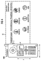
- FIG. 4 shows a schematic representation of a mobile Multimedia communication terminal with an input device according to a second embodiment. Same reference numbers denote the same or corresponding components in FIG. 4 as in Figures 3a and 3b, which is why on a detailed Description is waived below.
- the display unit 2 does not provide the complete website IS, but only a selective section Q. This way of presenting information, for example from the Internet or another application owns the Advantage that the information on the displayed page is for have improved readability for the user.
- the input device has now an intuitive control of the information page to be displayed IS. More specifically, a user needs the mobile Multimedia communication terminal with the recording unit 1 just move in the x and y directions to get to the respective Areas of the information page IS to get through without further use of keys or input media the information page IS intuitive (i.e. moving one Viewing window) can be read out.
- the receiving unit 1 is on the front of the mobile multimedia communication terminal MM. However, it can also be found on the back of the device or a second recording unit on the back of the mobile multimedia communication terminal MM arranged his. With a suitable design of the optics, d. H. a focus the recording unit 1 is also at a very short distance possible, the mobile multimedia communication terminal MM with the back: e on a suitable structured Underlay can be placed and moved as a whole like a mouse become. The recording unit on the back recognizes, as described above, the relative movement or relative displacement of the recorded Image information (structured document) and determined from this the corresponding control information for activation the selection information, d. H.
- Figures 5a to 5c show enlarged partial views of a mobile Multimedia communication terminal MM with an input device according to a third embodiment.
- Figures 5a to 5c designate the same reference numerals Components as in Figures 1 to 4, which is why a detailed Description is waived below.
- FIG. 5a the input device according to the third embodiment in the same way as a so-called conventional "touch pad" input device used become.
- reference numeral 1 again designates a recording unit 1, which, however, a special macro camera system represents. More specifically, the recording unit has 1 according to Figures 5a to 5c the possibility of very fine To record structures in the immediate vicinity of the camera for example the finger lines on the recording unit immediately picked up finger become.
- the display unit 2 shows a telephone book list according to FIGS. 5a to 5c with a variety of names and associated names Phone numbers.
- the phone book list shown in the display unit 2 corresponds to an information page IS, wherein the selection information is neither a pointer symbol P for Specify a selection position still a display area F, but a predetermined selection field B in the form of, for example color-coded bar.
- the input device via the Activation key T not shown, is activated.
- Figure 5b are now the finger lines as image information A added, allowing the user to move the bar B moved his finger down.
- 5c shows here is a partial view of the mobile multimedia communication terminal MM, with the finger in a lower position is shown.
- the recording unit 1 accordingly a shift of the recorded image information A ⁇ A ' recognized on the basis of the finger lines and as vertical Downward shift evaluated.
- the data processing unit 4 is output, whereby the bar B is shifted downwards in the display unit 2 and now the desired name Meier with the telephone number 345678.
- the input device can be used to select the desired name according to the third embodiment also a Pressure sensor to confirm the displayed selection information, i.e. of the name highlighted by the bar B, whereby further fixed keys or so-called menu-driven "soft keys" can be saved.
- the evaluation unit 3 can also make an input take place, as for example from conventional "touch pads” and / or “touch screens” is known.
- a pressure sensor in the receiving unit 1 Space requirements for the input device further reduced and the ease of use improved.
- the third embodiment is not a focus one Contact area determined, but the exact position or movement traced the finger on the basis of its line drawing. Therefore, the accuracy of this input device is essential larger than with conventional input devices. Essentially, this also applies to the input device according to the third embodiment, a relative macro shift the recorded image information for control purposes of selection information.
- a CCD or CMOS sensor camera is preferably used as the recording unit 1 used.
- the recording unit 1 is located either at the front or at the back of one respective input or computer system, but it is not limited to this and can also be in another position be arranged and, for example, in a mirror the display direction of the display unit 2 is the same or opposite Direction to be redirected.
- the invention has been described above using a mobile multimedia communication terminal described. However, it is not limited to and in the same way includes microcomputer systems without communication link, such as B. so-called Palm devices. In the same way, the present invention also on corded telecommunication devices and other computer systems are used.
Landscapes
- Engineering & Computer Science (AREA)
- General Engineering & Computer Science (AREA)
- Theoretical Computer Science (AREA)
- Human Computer Interaction (AREA)
- Physics & Mathematics (AREA)
- General Physics & Mathematics (AREA)
- Signal Processing (AREA)
- Position Input By Displaying (AREA)
- User Interface Of Digital Computer (AREA)
- Image Processing (AREA)
- Image Analysis (AREA)
Abstract
Description
Claims (17)
- Eingabevorrichtung für Computer Systeme mit
einer Aufnahmeeinheit (1) zum seriellen Aufnehmen von Bildinformationen (A, A');
einer Bildauswerteeinheit (3) zum Auswerten der aufgenommenen Bildinformationen (A, A') und Ermitteln von Steuerinformationen (x, y, z);
einer Datenverarbeitungseinheit (4) zum Verarbeiten der Steuerinformationen (x, y, z) in Auswahlinformationen(P; B; F); und
einer Anzeigeeinheit (2) zum Anzeigen der Auswahlinformationen (P; B; F), wobei
die Bildauswerteeinheit (3) die Steuerinformationen (x, y, z) aus einer relativen Verschiebung der seriell aufgenommenen Bildinformationen (A, A') ermittelt,
dadurch gekennzeichnet, daß
die Bildauswerteeinheit (3) eine Bildkompressionseinrichtung zum Erzeugen von Bewegungsvektoren aufweist, wobei die Steuerinformationen einen Haupt-Bewegungsvektor (x, y, z) der seriell aufgenommenen Bildinformationen (A, A') darstellen. - Eingabevorrichtung nach Patentanspruch 1,
dadurch gekennzeichnet, daß die Auswahlinformation in einem angezeigten Bild (IS) eine Auswahlposition (P), ein Auswahlfeld (B) und/oder eine gesamte Anzeigefläche (F) der Anzeigeeinheit (2) darstellt. - Eingabevorrichtung nach Patentanspruch 1 oder 2,
dadurch gekennzeichnet, daß die Steuerinformationen eine x-Komponente aufweisen, wobei die Bildauswerteeinheit (3) im wesentlichen eine parallele relative Verschiebung der Bildinformationen (A, A') in x-Richtung berücksichtigt. - Eingabevorrichtung nach einem der Patentansprüche 1 bis 3, dadurch gekennzeichnet, daß die Steuerinformationen eine y-Kornponente aufweisen, wobei die Bildauswerteeinheit (3) im wesentlichen eine parallele relative Verschiebung der Bildinformationen (A, A') in y-Richtung berücksichtigt.
- Eingabevorrichtung nach einem der Patentansprüche 1 bis 4, dadurch gekennzeichnet, daß die Steuerinformationen eine z-Komponente aufweisen, wobei die Bildauswerteeinheit (3) im wesentlichen eine konzentrische relative Verschiebung der Bildinformationen (A, A') in x- und y-Richtung berücksichtigt.
- Eingabevorrichtung nach Patentanspruch 5, dadurch gekennzeichnet, daß die Aufnahmeeinheit (1) eine Verschiebevorrichtung zum Erzeugen der parallelen und/oder konzentrischen relativen Verschiebung aufweist.
- Eingabevorrichtung nach Patentanspruch 5 oder 6,
dadurch gekennzeichnet, daß die Anzeigeeinheit (2) die Auswahlinformation (F) in Abhängigkeit von der z-Komponente der Steuerinformation vergrößert oder verkleinert. - Eingabevorrichtung nach einem der Patentansprüche 1 bis 7, dadurch gekennzeichnet, daß das Computersystem ein mobiles Multimedia-Kommunikationsendgerät (MM) darstellt.
- Eingabevorrichtung nach Patentanspruch 8,
dadurch gekennzeichnet, daß die Aufnahmeeinheit (1) in Anzeigerichtung der Anzeigeeinheit (2) aufnimmt. - Eingabevorrichtung nach einem der Patentansprüche 8 oder 9, dadurch gekennzeichnet, daß die Aufnahmeeinheit (1) entgegen der Anzeigerichtung der Anzeigeeinheit (2) aufnimmt.
- Eingabevorrichtung nach Patentanspruch 8 oder 9, gekennzeichnet durch zumindest eine weitere Aufnahmeeinheit, die entgegen der Anzeigerichtung der Anzeigeeinheit (2) aufnimmt.
- Eingabevorrichtung nach einem der Patentansprüche 1 bis 11, dadurch gekennzeichnet, daß die Aufnahmeeinheit eine CCD- oder CMOS-Sensorkamera aufweist.
- Eingabevorrichtung nach einem der Patentansprüche 1 bis 12, gekennzeichnet durch zumindest eine Aktiviexungsvorrichtung (T) zum Aktivieren/Deaktivieren der Eingabevorrichtung.
- Eingabevorrichtung nach einem der Patentansprüche 1 bis 13, dadurch gekennzeichnet, daß die Aufnahmeeinheit (1) ein Makro-Kamerasystem darstellt, mit dem die Bildinformationen (A, A') aus sehr kurzer Entfernung scharf aufgenommen werden.
- Eingabevorrichtung nach einem der Patentansprüche 1 bis 14, dadurch gekennzeichnet, daß die Aufnahmeeinheit (1) einen Drucksensor zum Bestätigen der angezeigten Auswahlinformation (P, B, F) aufweist.
- Eingabevorrichtung nach einem der Patentansprüche 1 bis 15, dadurch gekennzeichnet, daß das Computersystem ein mobiles Bildtelefon darstellt.
- Verfahren zur Eingabe von Steuerinformationen in ein Computersystem bestehend aus den Schritten:dadurch gekennzeichnet, daßa) Aufnehmen von ersten Bildinformationen (A);b) Aufnehmen von zweiten Bildinformationen (A');c) Ermitteln einer relativen Verschiebung zwischen den ersten und zweiten Bildinformationen; undd) Erzeugen der Steuerinformationen (x, y, z) auf der Grundlage der ermittelten relativen Verschiebung
das Ermitteln in Schritt c) ein Ermitteln von Bewegungsvektoren mittels eines Bild-Kompressionsverfahrens darstellt; und das Erzeugen gemäß Schritt d) ein Erzeugen von Steuerinformationen (x, y, z) auf der Grundlage eines Haupt-Bewegungsvektors darstellt.
Priority Applications (1)
| Application Number | Priority Date | Filing Date | Title |
|---|---|---|---|
| EP00940405A EP1194883B1 (de) | 1999-06-25 | 2000-06-26 | Vorrichtung und verfahren zur eingabe von steuerinformationen in computersysteme |
Applications Claiming Priority (4)
| Application Number | Priority Date | Filing Date | Title |
|---|---|---|---|
| EP99112287A EP1063607A1 (de) | 1999-06-25 | 1999-06-25 | Vorrichtung und Verfahren zur Eingabe von Streuerinformationen in Computersysteme |
| EP99112287 | 1999-06-25 | ||
| PCT/EP2000/005917 WO2001001334A1 (de) | 1999-06-25 | 2000-06-26 | Vorrichtung und verfahren zur eingabe von steuerinformationen in computersysteme |
| EP00940405A EP1194883B1 (de) | 1999-06-25 | 2000-06-26 | Vorrichtung und verfahren zur eingabe von steuerinformationen in computersysteme |
Publications (2)
| Publication Number | Publication Date |
|---|---|
| EP1194883A1 EP1194883A1 (de) | 2002-04-10 |
| EP1194883B1 true EP1194883B1 (de) | 2003-01-02 |
Family
ID=8238434
Family Applications (2)
| Application Number | Title | Priority Date | Filing Date |
|---|---|---|---|
| EP99112287A Withdrawn EP1063607A1 (de) | 1999-06-25 | 1999-06-25 | Vorrichtung und Verfahren zur Eingabe von Streuerinformationen in Computersysteme |
| EP00940405A Expired - Lifetime EP1194883B1 (de) | 1999-06-25 | 2000-06-26 | Vorrichtung und verfahren zur eingabe von steuerinformationen in computersysteme |
Family Applications Before (1)
| Application Number | Title | Priority Date | Filing Date |
|---|---|---|---|
| EP99112287A Withdrawn EP1063607A1 (de) | 1999-06-25 | 1999-06-25 | Vorrichtung und Verfahren zur Eingabe von Streuerinformationen in Computersysteme |
Country Status (5)
| Country | Link |
|---|---|
| EP (2) | EP1063607A1 (de) |
| JP (1) | JP2003503773A (de) |
| DE (1) | DE50001019D1 (de) |
| ES (1) | ES2190782T3 (de) |
| WO (1) | WO2001001334A1 (de) |
Families Citing this family (11)
| Publication number | Priority date | Publication date | Assignee | Title |
|---|---|---|---|---|
| US6977645B2 (en) * | 2001-03-16 | 2005-12-20 | Agilent Technologies, Inc. | Portable electronic device with mouse-like capabilities |
| FI117488B (fi) | 2001-05-16 | 2006-10-31 | Myorigo Sarl | Informaation selaus näytöllä |
| WO2003045440A1 (en) | 2001-11-28 | 2003-06-05 | Angiogenetics Sweden Ab | Regulation of hypoxia-inducible gene expression with antisense inhibitory pas domain protein |
| US7391888B2 (en) | 2003-05-30 | 2008-06-24 | Microsoft Corporation | Head pose assessment methods and systems |
| FI20045078L (fi) * | 2004-03-16 | 2005-09-17 | Myorigo Oy | Laajakulmaoptiikalla ja säteilysensorilla varustettu mobiililaite |
| JP4241484B2 (ja) | 2004-04-14 | 2009-03-18 | 日本電気株式会社 | 携帯端末装置、着信応答メッセージ送信方法およびサーバ装置 |
| FR2887654A1 (fr) * | 2005-06-24 | 2006-12-29 | Daniel Henri Lucien Jos Martin | Dispositif de pointage digital sur ecran |
| DE102005054984B4 (de) * | 2005-11-16 | 2008-03-27 | Vodafone Holding Gmbh | Mobiles Endgerät zur Nutzung in Mobilfunknetzen |
| US8994644B2 (en) | 2007-01-26 | 2015-03-31 | Apple Inc. | Viewing images with tilt control on a hand-held device |
| JP4330637B2 (ja) * | 2007-02-19 | 2009-09-16 | シャープ株式会社 | 携帯機器 |
| US20100149100A1 (en) * | 2008-12-15 | 2010-06-17 | Sony Ericsson Mobile Communications Ab | Electronic Devices, Systems, Methods and Computer Program Products for Detecting a User Input Device Having an Optical Marker Thereon |
Family Cites Families (9)
| Publication number | Priority date | Publication date | Assignee | Title |
|---|---|---|---|---|
| JPH04158434A (ja) * | 1990-10-23 | 1992-06-01 | Toshiba Corp | ディスプレイ装置のポインティングデバイス |
| JP3234633B2 (ja) * | 1992-06-19 | 2001-12-04 | シャープ株式会社 | 情報処理装置 |
| JPH07141098A (ja) * | 1993-11-17 | 1995-06-02 | Nippon Telegr & Teleph Corp <Ntt> | 座標入力装置 |
| TW320717B (de) * | 1995-11-13 | 1997-11-21 | Motorola Inc | |
| JP3050808B2 (ja) * | 1996-06-28 | 2000-06-12 | 財団法人大阪科学技術センター | 位置指示装置 |
| JPH1049290A (ja) * | 1996-08-05 | 1998-02-20 | Sony Corp | 情報処理装置および方法 |
| JPH10240436A (ja) * | 1996-12-26 | 1998-09-11 | Nikon Corp | 情報処理装置および記録媒体 |
| JPH112868A (ja) * | 1997-06-13 | 1999-01-06 | Nikon Corp | 電子カメラ、銀塩カメラ、電子カメラの制御方法、銀塩カメラの制御方法、および、記録媒体 |
| CA2208179A1 (en) * | 1997-06-18 | 1998-12-18 | Roland S. Walch | Pointing device with optical fingerprint recognition and tracking capability |
-
1999
- 1999-06-25 EP EP99112287A patent/EP1063607A1/de not_active Withdrawn
-
2000
- 2000-06-26 JP JP2001506486A patent/JP2003503773A/ja active Pending
- 2000-06-26 EP EP00940405A patent/EP1194883B1/de not_active Expired - Lifetime
- 2000-06-26 DE DE50001019T patent/DE50001019D1/de not_active Expired - Lifetime
- 2000-06-26 WO PCT/EP2000/005917 patent/WO2001001334A1/de not_active Ceased
- 2000-06-26 ES ES00940405T patent/ES2190782T3/es not_active Expired - Lifetime
Also Published As
| Publication number | Publication date |
|---|---|
| ES2190782T3 (es) | 2003-08-16 |
| JP2003503773A (ja) | 2003-01-28 |
| DE50001019D1 (de) | 2003-02-06 |
| EP1194883A1 (de) | 2002-04-10 |
| WO2001001334A1 (de) | 2001-01-04 |
| EP1063607A1 (de) | 2000-12-27 |
Similar Documents
| Publication | Publication Date | Title |
|---|---|---|
| DE69727530T2 (de) | Umgebung für Videobenutzer | |
| DE69635132T2 (de) | Endgerät | |
| DE69629144T2 (de) | Verfahren und Vorrichtung zur Kamerakontrolle | |
| DE102018116244A1 (de) | Verformbares elektrisches Gerät und Verfahren und Systeme zum Steuern der verformten Benutzerschnittstelle | |
| DE202007019556U1 (de) | Videokommunikationsendgerät zum Anzeigen von Bildern | |
| DE102018005131A1 (de) | Mobiles Gerät mit Frontkamera und maximierter Bildschirmoberfläche | |
| DE202017002875U1 (de) | Benutzerschnittstelle für Kameraeffekte | |
| DE10209797A1 (de) | Optische Pseudo-Rollkugel zur Steuerung des Betriebs einer Vorrichtung oder Maschine | |
| DE202011110758U1 (de) | Mobiles Endgerät | |
| EP1063607A1 (de) | Vorrichtung und Verfahren zur Eingabe von Streuerinformationen in Computersysteme | |
| DE102007032753A1 (de) | Mobiles Endgerät mit einer Dreheingabevorrichtung und Verfahren zur Empfindlichkeitseinstellung unter Verwendung derselben | |
| DE112019001607T5 (de) | Informationsverarbeitungseinrichtung, informationsverarbeitungsverfahren und programm | |
| DE102007029630A1 (de) | Systeme und Verfahren zum Erfassen von Objektbildern | |
| DE29722222U1 (de) | Funkbetriebenes Kommunikationsendgerät mit Navigationstaste | |
| DE102007056828A1 (de) | Eingabevorrichtung für ein mobiles Endgerät mit einer Scroll-Taste | |
| DE202006021123U1 (de) | Mobiles Kommunikationsgerät zur Nachrichtenanzeige | |
| DE10028138A1 (de) | Vorrichtung zur mobilen Kommunikation | |
| WO2001008409A1 (de) | Mobiles bildtelefon | |
| DE10317542A1 (de) | Mobiltelefon und Vorrichtung zur Datenverarbeitung | |
| DE102008029915A1 (de) | Verfahren und System zum Durchsuchen von Bildern unter Verwendung eines Tastenfelds | |
| EP2898402B1 (de) | Clientvorrichtung, überwachungssystem, verfahren zum anzeigen von bildern auf einem bildschirm sowie computerprogramm | |
| DE102014224898A1 (de) | Verfahren zum Betreiben einer Eingabevorrichtung, Eingabevorrichtung | |
| WO2005088546A1 (de) | Verfahren zur darstellung eines grafikobjekts und kommunikationsgerät | |
| DE102012100564B4 (de) | Anzeigeeinheit für eine Türstation | |
| WO2019072500A1 (de) | Fortbewegungsmittel, anwenderschnittstelle und verfahren zum bedienen einer anwenderschnittstelle |
Legal Events
| Date | Code | Title | Description |
|---|---|---|---|
| PUAI | Public reference made under article 153(3) epc to a published international application that has entered the european phase |
Free format text: ORIGINAL CODE: 0009012 |
|
| 17P | Request for examination filed |
Effective date: 20011108 |
|
| AK | Designated contracting states |
Kind code of ref document: A1 Designated state(s): AT BE CH CY DE DK ES FI FR GB GR IE IT LI LU MC NL PT SE |
|
| GRAG | Despatch of communication of intention to grant |
Free format text: ORIGINAL CODE: EPIDOS AGRA |
|
| GRAG | Despatch of communication of intention to grant |
Free format text: ORIGINAL CODE: EPIDOS AGRA |
|
| GRAH | Despatch of communication of intention to grant a patent |
Free format text: ORIGINAL CODE: EPIDOS IGRA |
|
| 17Q | First examination report despatched |
Effective date: 20020627 |
|
| GRAH | Despatch of communication of intention to grant a patent |
Free format text: ORIGINAL CODE: EPIDOS IGRA |
|
| GRAA | (expected) grant |
Free format text: ORIGINAL CODE: 0009210 |
|
| AK | Designated contracting states |
Kind code of ref document: B1 Designated state(s): DE ES FR GB IT |
|
| REG | Reference to a national code |
Ref country code: GB Ref legal event code: FG4D Free format text: 20030102:NOT ENGLISH |
|
| REG | Reference to a national code |
Ref country code: IE Ref legal event code: FG4D Free format text: GERMAN |
|
| REF | Corresponds to: |
Ref document number: 50001019 Country of ref document: DE Date of ref document: 20030206 Kind code of ref document: P |
|
| GBT | Gb: translation of ep patent filed (gb section 77(6)(a)/1977) |
Effective date: 20030331 |
|
| REG | Reference to a national code |
Ref country code: ES Ref legal event code: FG2A Ref document number: 2190782 Country of ref document: ES Kind code of ref document: T3 |
|
| REG | Reference to a national code |
Ref country code: IE Ref legal event code: FD4D Ref document number: 1194883E Country of ref document: IE |
|
| ET | Fr: translation filed | ||
| PLBE | No opposition filed within time limit |
Free format text: ORIGINAL CODE: 0009261 |
|
| STAA | Information on the status of an ep patent application or granted ep patent |
Free format text: STATUS: NO OPPOSITION FILED WITHIN TIME LIMIT |
|
| 26N | No opposition filed |
Effective date: 20031003 |
|
| REG | Reference to a national code |
Ref country code: GB Ref legal event code: 732E Free format text: REGISTERED BETWEEN 20101028 AND 20101103 |
|
| PGFP | Annual fee paid to national office [announced via postgrant information from national office to epo] |
Ref country code: GB Payment date: 20140618 Year of fee payment: 15 |
|
| PGFP | Annual fee paid to national office [announced via postgrant information from national office to epo] |
Ref country code: IT Payment date: 20140624 Year of fee payment: 15 Ref country code: ES Payment date: 20140627 Year of fee payment: 15 Ref country code: DE Payment date: 20140619 Year of fee payment: 15 |
|
| PGFP | Annual fee paid to national office [announced via postgrant information from national office to epo] |
Ref country code: FR Payment date: 20140619 Year of fee payment: 15 |
|
| REG | Reference to a national code |
Ref country code: DE Ref legal event code: R119 Ref document number: 50001019 Country of ref document: DE |
|
| PG25 | Lapsed in a contracting state [announced via postgrant information from national office to epo] |
Ref country code: IT Free format text: LAPSE BECAUSE OF NON-PAYMENT OF DUE FEES Effective date: 20150626 |
|
| GBPC | Gb: european patent ceased through non-payment of renewal fee |
Effective date: 20150626 |
|
| REG | Reference to a national code |
Ref country code: FR Ref legal event code: ST Effective date: 20160229 |
|
| PG25 | Lapsed in a contracting state [announced via postgrant information from national office to epo] |
Ref country code: GB Free format text: LAPSE BECAUSE OF NON-PAYMENT OF DUE FEES Effective date: 20150626 Ref country code: DE Free format text: LAPSE BECAUSE OF NON-PAYMENT OF DUE FEES Effective date: 20160101 |
|
| PG25 | Lapsed in a contracting state [announced via postgrant information from national office to epo] |
Ref country code: FR Free format text: LAPSE BECAUSE OF NON-PAYMENT OF DUE FEES Effective date: 20150630 |
|
| REG | Reference to a national code |
Ref country code: ES Ref legal event code: FD2A Effective date: 20160801 |
|
| PG25 | Lapsed in a contracting state [announced via postgrant information from national office to epo] |
Ref country code: ES Free format text: LAPSE BECAUSE OF NON-PAYMENT OF DUE FEES Effective date: 20150627 |