EP1192110B1 - Optical fiber having low polarization-mode dispersion and low attenuation and method of its manufacture - Google Patents
Optical fiber having low polarization-mode dispersion and low attenuation and method of its manufacture Download PDFInfo
- Publication number
- EP1192110B1 EP1192110B1 EP00957230A EP00957230A EP1192110B1 EP 1192110 B1 EP1192110 B1 EP 1192110B1 EP 00957230 A EP00957230 A EP 00957230A EP 00957230 A EP00957230 A EP 00957230A EP 1192110 B1 EP1192110 B1 EP 1192110B1
- Authority
- EP
- European Patent Office
- Prior art keywords
- glass
- core
- fiber
- centerline
- preform
- Prior art date
- Legal status (The legal status is an assumption and is not a legal conclusion. Google has not performed a legal analysis and makes no representation as to the accuracy of the status listed.)
- Expired - Lifetime
Links
- 238000000034 method Methods 0.000 title claims abstract description 74
- 239000013307 optical fiber Substances 0.000 title claims abstract description 73
- 238000004519 manufacturing process Methods 0.000 title claims abstract description 28
- 239000006185 dispersion Substances 0.000 title claims description 19
- 239000011521 glass Substances 0.000 claims abstract description 171
- 239000000835 fiber Substances 0.000 claims abstract description 114
- 239000004071 soot Substances 0.000 claims description 66
- 238000005253 cladding Methods 0.000 claims description 20
- 230000008569 process Effects 0.000 claims description 19
- 238000000151 deposition Methods 0.000 claims description 15
- 230000010287 polarization Effects 0.000 claims description 14
- 238000010438 heat treatment Methods 0.000 claims description 11
- 239000000463 material Substances 0.000 claims description 7
- 238000011109 contamination Methods 0.000 claims description 5
- 239000011800 void material Substances 0.000 claims description 5
- 230000003287 optical effect Effects 0.000 abstract description 44
- 239000011162 core material Substances 0.000 description 134
- 239000007789 gas Substances 0.000 description 31
- XLYOFNOQVPJJNP-UHFFFAOYSA-N water Substances O XLYOFNOQVPJJNP-UHFFFAOYSA-N 0.000 description 22
- VYPSYNLAJGMNEJ-UHFFFAOYSA-N Silicium dioxide Chemical compound O=[Si]=O VYPSYNLAJGMNEJ-UHFFFAOYSA-N 0.000 description 18
- 238000001035 drying Methods 0.000 description 16
- 238000007596 consolidation process Methods 0.000 description 14
- 230000013011 mating Effects 0.000 description 10
- 239000001257 hydrogen Substances 0.000 description 9
- 229910052739 hydrogen Inorganic materials 0.000 description 9
- 230000009467 reduction Effects 0.000 description 9
- 239000000377 silicon dioxide Substances 0.000 description 9
- 239000012080 ambient air Substances 0.000 description 8
- YBMRDBCBODYGJE-UHFFFAOYSA-N germanium dioxide Chemical compound O=[Ge]=O YBMRDBCBODYGJE-UHFFFAOYSA-N 0.000 description 8
- 238000009987 spinning Methods 0.000 description 8
- 239000012535 impurity Substances 0.000 description 7
- 230000008901 benefit Effects 0.000 description 6
- UFHFLCQGNIYNRP-UHFFFAOYSA-N Hydrogen Chemical compound [H][H] UFHFLCQGNIYNRP-UHFFFAOYSA-N 0.000 description 5
- 239000007795 chemical reaction product Substances 0.000 description 5
- 238000004891 communication Methods 0.000 description 5
- 230000008021 deposition Effects 0.000 description 5
- 239000012530 fluid Substances 0.000 description 5
- ZAMOUSCENKQFHK-UHFFFAOYSA-N Chlorine atom Chemical compound [Cl] ZAMOUSCENKQFHK-UHFFFAOYSA-N 0.000 description 4
- QVGXLLKOCUKJST-UHFFFAOYSA-N atomic oxygen Chemical compound [O] QVGXLLKOCUKJST-UHFFFAOYSA-N 0.000 description 4
- 239000000460 chlorine Substances 0.000 description 4
- 229910052801 chlorine Inorganic materials 0.000 description 4
- 150000001875 compounds Chemical class 0.000 description 4
- 239000000470 constituent Substances 0.000 description 4
- 239000001301 oxygen Substances 0.000 description 4
- 229910052760 oxygen Inorganic materials 0.000 description 4
- 239000002243 precursor Substances 0.000 description 4
- 238000007789 sealing Methods 0.000 description 4
- 230000005540 biological transmission Effects 0.000 description 3
- 230000015572 biosynthetic process Effects 0.000 description 3
- -1 but not limited to Substances 0.000 description 3
- 230000008878 coupling Effects 0.000 description 3
- 238000010168 coupling process Methods 0.000 description 3
- 238000005859 coupling reaction Methods 0.000 description 3
- 230000000694 effects Effects 0.000 description 3
- 238000007537 lampworking Methods 0.000 description 3
- 238000010926 purge Methods 0.000 description 3
- 239000000126 substance Substances 0.000 description 3
- 239000000919 ceramic Substances 0.000 description 2
- 229910052681 coesite Inorganic materials 0.000 description 2
- 239000000356 contaminant Substances 0.000 description 2
- 238000002788 crimping Methods 0.000 description 2
- 229910052906 cristobalite Inorganic materials 0.000 description 2
- 230000007423 decrease Effects 0.000 description 2
- 239000002019 doping agent Substances 0.000 description 2
- 238000005516 engineering process Methods 0.000 description 2
- 230000001747 exhibiting effect Effects 0.000 description 2
- 238000012681 fiber drawing Methods 0.000 description 2
- 229910052732 germanium Inorganic materials 0.000 description 2
- GNPVGFCGXDBREM-UHFFFAOYSA-N germanium atom Chemical compound [Ge] GNPVGFCGXDBREM-UHFFFAOYSA-N 0.000 description 2
- 238000007496 glass forming Methods 0.000 description 2
- 239000001307 helium Substances 0.000 description 2
- 229910052734 helium Inorganic materials 0.000 description 2
- SWQJXJOGLNCZEY-UHFFFAOYSA-N helium atom Chemical compound [He] SWQJXJOGLNCZEY-UHFFFAOYSA-N 0.000 description 2
- 238000005259 measurement Methods 0.000 description 2
- 230000007246 mechanism Effects 0.000 description 2
- 229910052751 metal Inorganic materials 0.000 description 2
- 239000002184 metal Substances 0.000 description 2
- 150000002739 metals Chemical class 0.000 description 2
- 230000000116 mitigating effect Effects 0.000 description 2
- 239000000203 mixture Substances 0.000 description 2
- 238000012986 modification Methods 0.000 description 2
- 230000004048 modification Effects 0.000 description 2
- 230000001590 oxidative effect Effects 0.000 description 2
- 229910052682 stishovite Inorganic materials 0.000 description 2
- 229910052723 transition metal Inorganic materials 0.000 description 2
- 150000003624 transition metals Chemical class 0.000 description 2
- 229910052905 tridymite Inorganic materials 0.000 description 2
- 238000007740 vapor deposition Methods 0.000 description 2
- 238000005019 vapor deposition process Methods 0.000 description 2
- 238000012935 Averaging Methods 0.000 description 1
- KZBUYRJDOAKODT-UHFFFAOYSA-N Chlorine Chemical compound ClCl KZBUYRJDOAKODT-UHFFFAOYSA-N 0.000 description 1
- PXGOKWXKJXAPGV-UHFFFAOYSA-N Fluorine Chemical compound FF PXGOKWXKJXAPGV-UHFFFAOYSA-N 0.000 description 1
- 238000010521 absorption reaction Methods 0.000 description 1
- 239000003570 air Substances 0.000 description 1
- PNEYBMLMFCGWSK-UHFFFAOYSA-N aluminium oxide Inorganic materials [O-2].[O-2].[O-2].[Al+3].[Al+3] PNEYBMLMFCGWSK-UHFFFAOYSA-N 0.000 description 1
- 238000005452 bending Methods 0.000 description 1
- 239000012159 carrier gas Substances 0.000 description 1
- 230000008859 change Effects 0.000 description 1
- 238000005229 chemical vapour deposition Methods 0.000 description 1
- 238000004140 cleaning Methods 0.000 description 1
- 239000011248 coating agent Substances 0.000 description 1
- 238000000576 coating method Methods 0.000 description 1
- 238000007796 conventional method Methods 0.000 description 1
- 229910052593 corundum Inorganic materials 0.000 description 1
- 238000005137 deposition process Methods 0.000 description 1
- 238000001514 detection method Methods 0.000 description 1
- 230000001627 detrimental effect Effects 0.000 description 1
- 238000010586 diagram Methods 0.000 description 1
- 238000009792 diffusion process Methods 0.000 description 1
- 230000005670 electromagnetic radiation Effects 0.000 description 1
- 230000008030 elimination Effects 0.000 description 1
- 238000003379 elimination reaction Methods 0.000 description 1
- 239000002657 fibrous material Substances 0.000 description 1
- 229910052731 fluorine Inorganic materials 0.000 description 1
- 239000011737 fluorine Substances 0.000 description 1
- 239000003365 glass fiber Substances 0.000 description 1
- 125000004435 hydrogen atom Chemical group [H]* 0.000 description 1
- TUJKJAMUKRIRHC-UHFFFAOYSA-N hydroxyl Chemical compound [OH] TUJKJAMUKRIRHC-UHFFFAOYSA-N 0.000 description 1
- 230000001788 irregular Effects 0.000 description 1
- 239000007791 liquid phase Substances 0.000 description 1
- 239000011159 matrix material Substances 0.000 description 1
- 230000008018 melting Effects 0.000 description 1
- 238000002844 melting Methods 0.000 description 1
- 239000006060 molten glass Substances 0.000 description 1
- 239000013618 particulate matter Substances 0.000 description 1
- 238000004375 physisorption Methods 0.000 description 1
- 238000012545 processing Methods 0.000 description 1
- 239000000047 product Substances 0.000 description 1
- 235000012239 silicon dioxide Nutrition 0.000 description 1
- 238000005245 sintering Methods 0.000 description 1
- 239000007787 solid Substances 0.000 description 1
- 238000010561 standard procedure Methods 0.000 description 1
- 239000000758 substrate Substances 0.000 description 1
- 229920002994 synthetic fiber Polymers 0.000 description 1
- 239000012808 vapor phase Substances 0.000 description 1
- 239000002699 waste material Substances 0.000 description 1
- 229910001845 yogo sapphire Inorganic materials 0.000 description 1
Images


Classifications
-
- G—PHYSICS
- G02—OPTICS
- G02B—OPTICAL ELEMENTS, SYSTEMS OR APPARATUS
- G02B6/00—Light guides; Structural details of arrangements comprising light guides and other optical elements, e.g. couplings
- G02B6/02—Optical fibres with cladding with or without a coating
- G02B6/02214—Optical fibres with cladding with or without a coating tailored to obtain the desired dispersion, e.g. dispersion shifted, dispersion flattened
- G02B6/02285—Characterised by the polarisation mode dispersion [PMD] properties, e.g. for minimising PMD
-
- C—CHEMISTRY; METALLURGY
- C03—GLASS; MINERAL OR SLAG WOOL
- C03B—MANUFACTURE, SHAPING, OR SUPPLEMENTARY PROCESSES
- C03B37/00—Manufacture or treatment of flakes, fibres, or filaments from softened glass, minerals, or slags
- C03B37/01—Manufacture of glass fibres or filaments
- C03B37/012—Manufacture of preforms for drawing fibres or filaments
- C03B37/01205—Manufacture of preforms for drawing fibres or filaments starting from tubes, rods, fibres or filaments
- C03B37/01225—Means for changing or stabilising the shape, e.g. diameter, of tubes or rods in general, e.g. collapsing
- C03B37/0124—Means for reducing the diameter of rods or tubes by drawing, e.g. for preform draw-down
- C03B37/01245—Means for reducing the diameter of rods or tubes by drawing, e.g. for preform draw-down by drawing and collapsing
-
- C—CHEMISTRY; METALLURGY
- C03—GLASS; MINERAL OR SLAG WOOL
- C03B—MANUFACTURE, SHAPING, OR SUPPLEMENTARY PROCESSES
- C03B37/00—Manufacture or treatment of flakes, fibres, or filaments from softened glass, minerals, or slags
- C03B37/01—Manufacture of glass fibres or filaments
- C03B37/012—Manufacture of preforms for drawing fibres or filaments
- C03B37/014—Manufacture of preforms for drawing fibres or filaments made entirely or partially by chemical means, e.g. vapour phase deposition of bulk porous glass either by outside vapour deposition [OVD], or by outside vapour phase oxidation [OVPO] or by vapour axial deposition [VAD]
- C03B37/01466—Means for changing or stabilising the diameter or form of tubes or rods
- C03B37/01473—Collapsing
-
- C—CHEMISTRY; METALLURGY
- C03—GLASS; MINERAL OR SLAG WOOL
- C03B—MANUFACTURE, SHAPING, OR SUPPLEMENTARY PROCESSES
- C03B37/00—Manufacture or treatment of flakes, fibres, or filaments from softened glass, minerals, or slags
- C03B37/01—Manufacture of glass fibres or filaments
- C03B37/012—Manufacture of preforms for drawing fibres or filaments
- C03B37/014—Manufacture of preforms for drawing fibres or filaments made entirely or partially by chemical means, e.g. vapour phase deposition of bulk porous glass either by outside vapour deposition [OVD], or by outside vapour phase oxidation [OVPO] or by vapour axial deposition [VAD]
- C03B37/018—Manufacture of preforms for drawing fibres or filaments made entirely or partially by chemical means, e.g. vapour phase deposition of bulk porous glass either by outside vapour deposition [OVD], or by outside vapour phase oxidation [OVPO] or by vapour axial deposition [VAD] by glass deposition on a glass substrate, e.g. by inside-, modified-, plasma-, or plasma modified- chemical vapour deposition [ICVD, MCVD, PCVD, PMCVD], i.e. by thin layer coating on the inside or outside of a glass tube or on a glass rod
- C03B37/01861—Means for changing or stabilising the diameter or form of tubes or rods
- C03B37/01869—Collapsing
-
- C—CHEMISTRY; METALLURGY
- C03—GLASS; MINERAL OR SLAG WOOL
- C03B—MANUFACTURE, SHAPING, OR SUPPLEMENTARY PROCESSES
- C03B37/00—Manufacture or treatment of flakes, fibres, or filaments from softened glass, minerals, or slags
- C03B37/01—Manufacture of glass fibres or filaments
- C03B37/02—Manufacture of glass fibres or filaments by drawing or extruding, e.g. direct drawing of molten glass from nozzles; Cooling fins therefor
- C03B37/025—Manufacture of glass fibres or filaments by drawing or extruding, e.g. direct drawing of molten glass from nozzles; Cooling fins therefor from reheated softened tubes, rods, fibres or filaments, e.g. drawing fibres from preforms
- C03B37/027—Fibres composed of different sorts of glass, e.g. glass optical fibres
- C03B37/02754—Solid fibres drawn from hollow preforms
-
- G—PHYSICS
- G02—OPTICS
- G02B—OPTICAL ELEMENTS, SYSTEMS OR APPARATUS
- G02B6/00—Light guides; Structural details of arrangements comprising light guides and other optical elements, e.g. couplings
- G02B6/02—Optical fibres with cladding with or without a coating
- G02B6/036—Optical fibres with cladding with or without a coating core or cladding comprising multiple layers
- G02B6/03616—Optical fibres characterised both by the number of different refractive index layers around the central core segment, i.e. around the innermost high index core layer, and their relative refractive index difference
- G02B6/03622—Optical fibres characterised both by the number of different refractive index layers around the central core segment, i.e. around the innermost high index core layer, and their relative refractive index difference having 2 layers only
-
- C—CHEMISTRY; METALLURGY
- C03—GLASS; MINERAL OR SLAG WOOL
- C03B—MANUFACTURE, SHAPING, OR SUPPLEMENTARY PROCESSES
- C03B2201/00—Type of glass produced
- C03B2201/06—Doped silica-based glasses
- C03B2201/30—Doped silica-based glasses doped with metals, e.g. Ga, Sn, Sb, Pb or Bi
- C03B2201/31—Doped silica-based glasses doped with metals, e.g. Ga, Sn, Sb, Pb or Bi doped with germanium
-
- C—CHEMISTRY; METALLURGY
- C03—GLASS; MINERAL OR SLAG WOOL
- C03B—MANUFACTURE, SHAPING, OR SUPPLEMENTARY PROCESSES
- C03B2203/00—Fibre product details, e.g. structure, shape
- C03B2203/36—Dispersion modified fibres, e.g. wavelength or polarisation shifted, flattened or compensating fibres (DSF, DFF, DCF)
-
- C—CHEMISTRY; METALLURGY
- C03—GLASS; MINERAL OR SLAG WOOL
- C03B—MANUFACTURE, SHAPING, OR SUPPLEMENTARY PROCESSES
- C03B2205/00—Fibre drawing or extruding details
- C03B2205/08—Sub-atmospheric pressure applied, e.g. vacuum
-
- C—CHEMISTRY; METALLURGY
- C03—GLASS; MINERAL OR SLAG WOOL
- C03B—MANUFACTURE, SHAPING, OR SUPPLEMENTARY PROCESSES
- C03B2205/00—Fibre drawing or extruding details
- C03B2205/10—Fibre drawing or extruding details pressurised
Definitions
- the present invention relates generally to the field of optical waveguide fibers, and more particularly to methods of making low polarization-mode dispersion and low attenuation optical waveguide fibers.
- a significant goal of the telecommunications industry is to transmit greater amounts of information, over longer distances, in shorter periods of time.
- demand for system resources increases as well.
- One way of meeting this demand is by increasing the bandwidth of the medium used to carry the information.
- the demand for optical waveguide fibers having increased bandwidth is particularly high.
- optical waveguide fiber In recent years, significant advancements have been made in the manufacture of optical waveguide fiber, which in turn have increased the usable light carrying capacity of the fiber.
- electromagnetic radiation traveling through an optical waveguide fiber is subject to attenuation or loss due to several mechanisms. Although some of these mechanisms cannot be reduced, others have been eliminated, or at least substantially reduced.
- a particularly problematic mode of optical fiber attenuation is attenuation due to absorption by the optical waveguide fiber due to impurities present in the light guiding region of the fiber.
- Particularly troublesome is the attenuation caused by the hydroxyl radical (OH), which can be formed in the optical waveguide fiber when a source of hydrogen is present in the fiber material, or when hydrogen available from several sources during the fiber manufacturing process diffuses into the glass.
- OH hydroxyl radical
- the attenuation increase due to OH or water in the glass can be as high as about 0.5 to 1.0 dB/km, with the attenuation peak generally accompanying the 1380 nm window.
- 1380 nm window is defined as the range of wavelengths between about 1330 nm and about 1470 nm.
- the attenuation peak generally referred to as the water peak, has prevented useable electromagnetic transmission in the 1380 nm window.
- telecommunication systems avoid the water peak residing in the 1380 nm window by operating in the 1310 nm window and/or the 1550 nm window, among others.
- WDM wavelength division multiplexing
- amplifier technology which enable telecommunication systems to operate over broad wavelength ranges, it is likely that all wavelengths between about 1300 nm and about 1650 nm will be used for data transmission in optical telecommunication systems. Removing the water peak from optical waveguide fiber used with such systems is an important aspect of enabling system operation over this entire range.
- the soot core blank is formed by depositing silica and germanium containing precursor constituents in the presence of oxygen onto a ceramic bait rod. As the bait rod is rotated, the precursor constituents are delivered to the flame burner to produce soot, and that soot is then deposited onto the bait rod. Once sufficient soot is deposited, the bait rod is removed, and the resultant soot core blank can be consolidated into a glass core blank.
- the soot core blank is typically consolidated by hanging the soot core blank in a consolidation furnace and heating the soot core blank to a temperature and for a time sufficient to consolidate the soot core blank into a glass.
- the soot core blank is chemically dried, for example, by exposing the soot core blank to chlorine gas at an elevated temperature. The result is a cylindrical glass core blank having an axial hole along its centerline.
- This glass core blank is then typically drawn, e.g., by positioning the glass core blank in a furnace, heating the core blank to a temperature of approximately 2000°C, and then redrawing or stretching the core blank into a smaller diameter core cane.
- the centerline hole of the core blank is collapsed by applying considerable vacuum (e.g., a pressure of less than 200 mTorr) along the centerline hole. These vacuum forces ensure complete closure of the glass core blank along the centerline.
- the resulting core cane is then typically overclad with a layer of cladding soot by depositing a cladding soot, e.g. via an OVD deposition process.
- the resultant soot overclad core cane is chemically dried and consolidated to form an optical fiber preform.
- different processes e.g. MCVD and others
- MCVD chemical vapor deposition
- these manufacturing processes typically involve utilizing a vacuum at some point during the manufacturing process to close the hole or gap which is present between glass constituents without changing the outer diameter significantly.
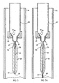
- Fig. 1 illustrates a cross section of core cane, indicated generally at 10, which includes a center point 12 surrounded by layers of glass 14.
- these glass layers 14 have an irregular, asymmetric shape, as a result of the application of the vacuum forces during redraw. Only at locations farther from the center point 12 do the layers of glass 16 begin to form more symmetrical and concentric circles or rings about the center point 12.
- the same non-symmetrical layers of glass present in the core cane will be present when that cane is eventually drawn into an optical fiber. Views of the centerline profile taken at different locations along the length of the core cane (or the optical fiber resulting therefrom) would also show core asymmetry. Further, the geometrical properties of the core cane and resultant optical fiber may change along the length thereof. More specifically, the specific asymmetrical shape at one location along the optical fiber might differ from the shape at another location along the optical fiber.
- PMD polarization mode dispersion
- single mode fibers and multimode fibers both have an outside diameter of generally about 125 microns.
- single mode fibers have a small, e.g., about 8 micron, core diameter. This dimensional relationship makes single mode fibers extremely sensitive to polarization mode dispersion brought on by non-symmetric hole closure caused during fiber manufacture.
- the core region of a multimode fiber commonly has a diameter of 62.5 microns or 50 microns.
- non-symmetric hole closure has resulted in the inability to tune refractive index profiles on the inner-most portion of the fiber adjacent the centerline.
- lasers used to launch light into such fibers are often offset some distance from the centerline of the multimode fiber to avoid this region of non-symmetric hole closure.
- One method used to reduce PMD is spinning of the optical fiber during the fiber draw operation, wherein the fiber is mechanically twisted along its centerline axis while being drawn from the molten root of the blank. This twisting enables orthogonal components of light to couple to each other, thus averaging their dispersion and lowering PMD.
- spinning is a fairly complicated process for mitigating the effects of non-symmetric hole closure, and can impede the draw speed, cause coating geometry perturbations, reduce the strength of the optical fiber and so forth. It would therefore be desirable to manufacture fibers having a low PMD without resorting to such spinning techniques.
- asymmetric core geometry can cause variations in core diameter along the length of the fiber core so that transmitted light "sees" a different core cross-sectional area at different points along the length of the optical fiber.
- an asymmetric centerline profile can reduce the bandwidth of laser launched multimode fiber.
- the blanks are chemically dried and sintered during consolidation, it has been found that the region of glass surrounding and defining the centerline hole is being rewet after drying. Most commonly, such rewetting occurs through the physisorption, chemisorption, or diffusion of water upon exposure of the centerline hole to an atmosphere that includes a hydrogen containing compound, such as, but not limited to water (H 2 O) following consolidation.
- a hydrogen containing compound such as, but not limited to water (H 2 O) following consolidation.
- US-A-4154591 describes a method of making an optical fiber constructed of layers of glass and having a centerline, and a fiber cladding surrounding the fiber core, which is said to be of improved cross sectional circularity.
- the method comprises the steps of forming a hollow, cylindrical optical fiber preform, and maintaining in the bore of the preform a pressure greater than that of the ambient surroundings while reducing the diameter of the preform to yield a solid cylindrical optical fiber preform.
- the present invention relates to a method of making an optical fiber comprising the steps of providing an intermediate glass object in the form of a core glass blank for use in the manufacture of optical fiber, the glass object having a centerline hole therein, heating the glass object to a temperature sufficient to reduce the diameter of the glass object and reducing the outside diameter of the glass object while controlling the pressure inside the centerline hole sufficiently to result in uniform and symmetric hole closure.
- the present invention provides a method of making an optical fiber including a fiber core constructed of layers of glass and having a centerline, and a fiber cladding surrounding the fiber core, wherein the layers of glass surrounding the centerline are sufficiently circularly symmetric to result in a polarization mode dispersion of less than 0.2 psec/sqrt-km, and having an attenuation of less than or equal to 0.24 dB/km at 1550 nm, the method comprising the steps of forming a core glass blank having a centerline hole therein each end of which is plugged preventing gas flow therethrough; drawing the core glass blank while maintaining, but narrowing, the centerline hole therein, thereby to form an intermediate glass object; depositing cladding material on to the intermediate glass object; heating the intermediate glass object to a temperature sufficient to reduce the outside diameter of the glass object; opening at least one end of the intermediate glass object while protecting the centerline hole from contamination; applying a pressure of equal to or greater than about 1067 Pa (8 Torr) to the void; and
- the above mentioned pressure may be greater than 13332 Pa (100 Torr), and may be greater than 66661 Pa (500 Torr).
- the hole closure step is conducted under conditions which are sufficient to result in uniform symmetric heating of the intermediate glass object just prior to and/or during the hole closure step.
- symmetric heating could be achieved, for example, by utilizing a cylindrical furnace when the intermediate glass object is a cylindrically shaped optical fiber preform or other cylindrically shaped intermediate glass object.
- the fiber made by the method of the present invention may be used in an optical fiber communication system comprising a transmitter and a receiver, with the optical fiber communicating an optical signal between the transmitter and the receiver.
- the optical fiber may exhibit less than 3 spin rotations over a longitudinal fiber length of 1 meter.
- the method of the present invention further includes attaching an outer handle to the first end of the preform, wherein the outer handle has a mating end, providing an inner handle for coupling to a gas supply, wherein the inner handle has a mating end and a fluid receiving end, and coupling the mating end of the outer handle with the mating end of the inner handle.
- the method still further includes exposing the centerline hole of the preform to a gas, heating the preform to a temperature sufficient to soften the preform, and closing the centerline hole of the preform by drawing the preform down into an optical waveguide fiber.
- the first end is formed in a bent tab.
- the method further includes providing an outer handle integrally attached to the first end of the preform, wherein the outer handle has a mating end, providing an inner handle in fluid communication with a gas supply, wherein the inner handle has a mating end, a radially extending breaking tab, and a fluid receiving end, and coupling the mating end of the outer handle with the mating end of the inner handle.
- the method further includes heating the preform sufficiently to increase the pressure of gas within the centerline hole of the preform, exposing the centerline hole of the preform to a clean dry gas by rotating the outer handle and the inner handle relative to one another until the breaking tab of the inner handle contacts the bent tab of the preform, thereby breaking the bent tab, heating the glass body to a temperature sufficient to soften the preform, and closing the centerline hole of the preform by drawing the preform down into an optical waveguide fiber.
- optical fiber and other waveguides in accordance with the present invention achieves a number of advantages over the prior art with respect to the reduction of polarization mode dispersion. Because the centerline holes in the intermediate glass objects of the present invention are closed under conditions to result in uniform and symmetric hole closure, fibers drawn from such intermediate glass objects exhibit greatly reduced polarization mode dispersion compared to fibers in the prior art.
- the amount of positive or negative pressure applied during draw results in a fiber having a substantially circular centerline profile, i.e., a substantially circular core symmetry, wherein as one moves from the centerline outward, layers of adjacent glass retain a very circular symmetry.
- single mode fibers have been made which exhibit low polarization mode dispersion without having to resort to spinning or other PMD mitigation methods.
- the method of the present invention can also be used to form multimode optical fibers which are inherently better suited for use with laser sources.
- the spot size of the laser can be small relative to the overall size of the core. if the laser is directed at an area having non-symmetric glass layers, these non-symmetric glass layers can disturb the path along which the laser beam would otherwise travel. Consequently, it is desirable to have uniformly symmetric and concentric glass layers about the centerline of the core of the fiber. Such concentric layers are achievable using the method of the present invention.
- optical waveguide fiber made from such a core blank exhibits a much smaller water peak at 1380 nm, and in the 1380 nm window as a whole, therefore exhibits lower optical attenuation in a 1380 nm window than an optical waveguide fiber manufactured in accordance with standard methods from preforms manufactured by the OVD process. Further, optical waveguide fiber made from such a core blank exhibits reduced attenuation losses.
- An additional advantage of the method of the present invention is that optical waveguide fiber manufactured with such methods can now operate at any selected wavelength over a range of wavelengths from about 1300 nm to about 1680 nm without undue optical attenuation. Moreover, the method of the present invention is also economical to implement and can be practised without the production of additional environmentally unfriendly waste products.
- optical fibers produced according to the method may have less voids along their centerline. Elimination of the vacuum forces during hole diameter reduction and/or hole closure significantly reduces the likelihood of voids in the fiber, thereby reducing the light reflections associated therewith.
- optical waveguide fiber 30 manufactured by the method of the present invention is shown.
- the optical waveguide fiber includes a central core region 32 having a centrally located axis 33, an outer glass core region 34 and a coaxial cladding region 36.
- Optical waveguide fiber 30 is formed from a cylindrical glass body or glass preform 70 (Fig. 3) having a central core region 42 with a longitudinally extending, centrally located centerline hole 60 extending therethrough defining a centrally located axis 45.
- Preform 70 also includes an outer glass core region 46 and cladding region 48 both coaxial with core region 42.
- central core region 32 and 42 could consist of germanium doped central region, and region 34 and 46 could consist of additional regions having various amounts of fluorine and/or germania dopants, to form a complex index of refraction profile (e.g., a segcor profile).
- a complex index of refraction profile e.g., a segcor profile
- the invention is not limited to use with these dopants, nor is it limited to fibers having complex index of refraction profiles.
- region 34 may be omitted, and the fiber may be a simple step index profile.
- region 34 could include a near clad region, which consists of pure silica typically.
- cylindrical glass preform 70 is preferably formed by chemically reacting at least some of the constituents of a moving fluid mixture including at least one glass-forming precursor compound in an oxidizing medium to form a silica-based reaction product. At least a portion of this reaction product is directed toward a substrate, to form a porous body, at least a portion of which includes hydrogen bonded to oxygen.
- the porous body may be formed, for example, by depositing layers of soot onto a bait rod via an outside vapor deposition ("OVD") process.
- OLED outside vapor deposition
- a bait rod or mandrel 50 is inserted through a tubular integral handle 52 and mounted on a lathe (not shown).
- the lathe is designed to rotate and translate mandrel 50 in close proximity with a soot-generating burner 54.
- silica-based reaction product 56 known generally as soot, is directed toward mandrel 50.
- silica-based reaction product 56 is deposited on mandrel 50 and on a portion of integral handle 52 to form a cylindrical soot porous body or soot core blank 58 thereon having a proximal end 59 and a distal end 61. While this aspect of the present invention has been described in conjunction with a translating lathe, it will be understood by those skilled in the art that soot-generating burner 54 can translate rather than the mandrel 50. Moreover, this aspect of the present invention is not intended to limit soot deposition to an OVD process.
- soot deposition is terminated and mandrel 50 is removed from soot core blank 58.
- soot core blank 58 defines an axially extending void or centerline hole 60 (Fig. 5).
- Soot core blank 58 is vertically suspended within a consolidation furnace 64A by a downfeed handle 62 engaging integral handle 52.
- Consolidation furnace 64A preferable concentrically surrounds the soot core blank 58.
- Integral handle 52 is formed of a silica based glass material and includes a first end 63 about which proximal end 59 of core blank 58 is formed, and a second end 65 defining an inner surface 67 therein.
- second end 65 of integral handle 52 may be flame worked thereon subsequent to the deposition and consolidation steps.
- Integral handle 52 is generally cup-shaped and defines an interior cavity 69.
- Inner surface 67 is preferably provided with a coarse texture, the significance of which is discussed below.
- Centerline hole 60 located near distal end 61 of soot core blank 58 is preferably fitted with a glass bottom plug 66 prior to positioning porous body 58 within consolidation furnace 64A.
- Glass plug 66 is preferably made from a relatively low melting point glass (e.g. lower than that of the soot core blank) so that during consolidation, as the soot of the soot core blank is consolidated into glass, the glass plug will effectively seal the end of the centerline hole.
- bottom plug 66 is the preferable method for closing the distal end 61 of porous body 58
- other methods and devices sufficient to close distal end 61 to prohibit airflow therethrough may be employed such as, but not limited to, flaming and/or crimping the end 61 shut.
- the centerline hole 60 at proximal end 59 of core blank 58 may remain open to ambient air or may be closed by inserting a top plug 73 into centerline hole 60 prior to the consolidation step similar to bottom plug 66.
- the hole inside the integral handle is made larger than the hole inside the soot preform 58, and the size of plug 73 is selected to be intermediate these two internal diameters, so that the plug can be inserted through the integral handle portion 52, but gets stuck in the centerline hole region of preform 58.
- top plug 73 may consist of a thicker region (thick enough to plug the centerline hole 60 within the soot preform 58) at a bottom end which serves to plug the centerline hole 60 of soot preform 58, another thick region (thicker than the centerline hole in integral handle 52) at the top end of the plug to prevent the plug 73 from falling into the centerline hole 60 of soot preform 58, and an intermediate region between the two ends to connect these two thicker end regions.
- Soot core blank 58 is preferably chemically dried, for example, by exposing soot core blank 58 to a chlorine containing atmosphere at an elevated temperature within consolidation furnace 64A.
- the chlorine containing atmosphere effectively removes water and other impurities from soot core blank 58, which otherwise would have an undesirable effect on the properties of optical waveguide fiber manufactured from blank 58.
- the temperature of the furnace is elevated to a temperature sufficient to consolidate the soot into a sintered glass core blank 55.
- the glass core blank 55 is then used to form an intermediate glass object to the form of a core cane 57.
- Core cane has the conventional meaning in the art, that is, a consolidated glass rod or tube which includes at least a portion of the core region for an optical fiber preform, to which additional core and/or cladding material is added to form a complete optical fiber preform.
- the temperature of redraw furnace 64B is raised to a temperature which is sufficient to reduce the diameter of the consolidated glass core preform blank 55 to form core cane 57.
- centerline hole 60 will also narrow along with the outside diameter of core cane 57 (this narrowing is not illustrated in the drawings). However, centerline hole 60 does not completely close, as normally the diameter reduction of the initial outside diameter of core blank 55 is not sufficient, with respect to the initial inside diameter of centerline hole 60, to close centerline hole 60 without the aid of significant vacuum forces. Centerline hole 60 preferably remains closed at both ends so that, in effect, after the glass has been chemically dried and consolidated, there is no opportunity for the glass to take on water along centerline hole 60 during redraw into separate canes.
- the ends 51 and 51' of core cane 57 are sealed shut as they are separated from the core blank 58 by a plurality of torches 53 or dry heat sources (i.e., electric resistance furnaces) symmetrically spaced about core cane 57 which is being redrawn.
- a sealing step may be accomplished, for example, by flaming shut (as shown) or crimping shut the semi-molten ends of core cane 57 as each core cane 57 is separated. Sealing each end of core cane 57 without exposing centerline hole 60 to ambient air greatly reduces the amount of water and other impurities, such as transition metals, trapped within the centerline region associated therewith.
- bent tab 68 is drawn/pulled from the end of core cane 57 (Fig. 7) located nearest integral handle 52. This can be done by flame working and bending the end of core cane 57. Bent tab 68 extends radially outward from the center of glass preform 70. An integral handle 52 such as that shown in Fig. 6 is then attached to an end of each core cane 57 by flame working or any other suitable method which does not expose space 60 to the atmosphere.
- the core cane 57 is then moved to a cladding station, where additional core material and/or cladding material is overlaid on core cane 57.
- the overcladding step is identical to the initial soot deposition technique used to form the core soot blank 58 (Fig. 4), except instead of depositing the cladding soot onto a mandrel 50 it is overlaid onto core cane 57.
- This clad overlaying step may be accomplished by depositing the cladding material onto core cane 57 via, for example, soot deposition, or alternatively by inserting the cane into a cladding sleeve.
- This process may be repeated several times if additional core soot regions are to be formed, by placing the resultant glass core blank 55 (Fig. 6) within furnace 64 and drawing or pulling a new core cane 57A therefrom and then depositing still additional soot material thereon. Once the glass core cane has been overlaid with soot cladding, is then moved to a consolidation furnace, where the soot cladding is chemically dried and then consolidated into glass onto core cane 57 to form a complete glass fiber preform 70 (Fig. 7).
- the glass preform 70 was routinely exposed to a water containing environment, such as ambient atmosphere, at any one of several steps subsequent to the forming of the core blank and prior to the formation of optical fiber therefrom. It is now recognized that physisorbed water and chemisorbed water in the glass bounding the centerline hole 60 occurs almost instantaneously when the glass is exposed to atmosphere containing a hydrogen compound such as, but not limited to water (H 2 O). Moreover, the greater the exposure time, the greater the amount of water absorbed by the glass.
- a hydrogen compound such as, but not limited to water (H 2 O).
- any exposure to ambient atmosphere, or any atmosphere containing a hydrogen compound may rewet the portion of the glass preform bounding the centerline hole.
- Such rewetting provides the impurities that cause the water peak exhibited by optical waveguide fibers manufactured using standard fiber manufacture processing techniques from blanks formed by an OVD process.
- centerline hole 60 of the glass preform 70 Another disadvantage of exposing the centerline hole 60 of the glass preform 70 is that the centerline hole 60 may be exposed to other contaminates and impurities such as transitional metals. The inclusion of transitional metals within the resultant optical fiber contributes to attenuation losses. By completely sealing each end of centerline hole 60 as seen in Fig. 5B, the exposure of centerline hole 60 to detrimental impurities may be reduced or eliminated. Other techniques for avoiding water contamination are disclosed, for example, in U.S. Provisional Patent Application No. 60/131,033, filed April 26, 1999.
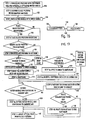
- the sintered glass preform 70 which includes core cane 57 overlaid with a cladding (Fig. 7) is formed it is moved to a draw furnace, preferably in a vertical orientation, for drawing the glass preform 70 into an optical waveguide fiber, as represented by step 100, Fig. 13.
- the glass preform 70 is suspended by integral handle 52 on downfeed handle 72, as represented by step 102.
- the furnace employed herein for hole closure of the intermediate glass object (regardless of whether the intermediate glass object is a core cane or, as in this case, an optical fiber preform) preferably employs a heat source which is symmetric about the periphery of the glass intermediate object.
- the heat source is a vertically oriented, cylindrical furnace having gradient heat zones.
- One such furnace employs heat zones of increasing temperature from top to bottom up. Consequently, as the glass intermediate object is inserted into the top of the furnace and lowered into it, the hole closes from the bottom.
- the ratio of the outside diameter of the intermediate object to the inside diameter of the centerline hole to be closed is great enough that, under sufficient reduction of the outside diameter, the hole closes without the need for negative pressure that would otherwise cause the hole to close non-uniformly.
- the downfeed handle 72 is positioned within and translatable within the draw furnace (not shown), and glass preform 70 is lowered within a draw furnace 74 which defines an interior wall 81, such as illustrated in Fig. 7.
- glass preform 70 is -encircled by interior wall 81 of draw furnace 74.
- a cylindrical inner handle 76 (Figs. 7 and 8) having a radially, inwardly extending breaking tab 80 is mated within integral handle 52 such that a lower end bowl-shaped, coarse textured mating surface 78 of inner handle 76 forms a substantially airtight seal with mating surface 67 of integral handle 52, as shown by step 104.
- Handle 76 has an interior cavity and at its lower end includes a breaking tab 80 which extends radially inwardly such that relative rotation between integral handle 52 and inner handle 76 causes breaking tab 80 of inner handle 76 to engage bent tab 68 of glass preform 70, as further discussed below.
- glass preform 70 is lowered into draw furnace or hot zone 74 for a sufficient time period to increase the gas pressure within centerline hole 60 of glass preform 70, as represented by step 106.
- Glass preform 70 is then removed from within hot zone 74, as represented by step 108.
- a negative pressure is applied to interior cavity 71 of inner handle 76 and interior cavity 69 of integral handle 52, thereby removing contaminates such as H 2 O as well as other particulate matter therefrom, as represented by step 110.
- the interior cavity 71 of inner handle 76 and the interior cavity 69 of integral handle 52 are then backfilled with a dry inert or drying gas (e.g. chlorine), as represented by step 112, from a gas supply 84 (Fig. 7).
- the supply of dry or drying gases is preferably provided so that if any gas enters centerline hole 60 of glass preform 70, it is a clean dry gas that will not lead to attenuation induced losses within the resultant optical waveguide fiber.
- centerline hole 60 of glass preform 70 is then opened by snapping bent tab 68 of glass preform 70, as represented by step 114.
- bent tab 68 can be scribed by at a point closer to the end of bent tab 68 than to the location at which bent tab 68 and integral handle 52 are connected, followed by the snapping of bent tab 68 of glass preform 70.
- inner handle 76 is rotated relative to integral handle 52 such that breaking tab 80 of inner handle 76 engages bent tab 68 of glass preform 70, as shown in Figs. 9 and 10, to break tab 68. Breaking bent tab 68 (Fig.
- glass preform 70 exposes centerline hole 60 of glass preform 70 to the gas within interior cavity 69 of integral handle 52, thereby reducing or eliminating possible contamination of centerline hole 60 prior to the drawing of optical waveguide fiber from glass preform 70. While rotating inner handle 76 relative to integral handle 52 is preferred, integral handle 52 could be rotated with respect to inner handle 76. Further, both inner handle 76 and integral handle 52 may be rotated with respect to one another.
- a dry or drying gas is continuously passed over inner handle 76 thereby maintaining interior cavity 71 of inner handle 76, interior cavity 69 of integral handle 52, and centerline hole 60 of glass preform 70 free of contaminants and from being recontaminated, as represented by step 116.
- a valve 82 is used to control the flow of gas from the gas supply 84 and whether the gas is directed directly to interior cavity 71 of inner handle 76 or vented to an exhaust tube 86.
- Exhaust tube 86 is coupled with a one-way valve 88 that prevents the entry of air into exhaust tube 86 and the contamination of centerline 60 of glass preform 70 by ambient air and the contaminant matter associated therewith, as represented by step 118.
- One-way valve 88 may be provided in the form of a bubbler, a check valve, or any other form of a one-way valve that prevents the backflow of ambient air into exhaust tube 86.
- exhaust tube 86 may be provided at such a substantial length that the backflow of ambient air into exhaust tube 86 is prevented from reaching centerline hole 60 of glass preform 70.
- the glass preform 70 is lowered further into the hot zone of furnace 74 and/or the temperature is increased to a temperature sufficient to allow an optical waveguide fiber 79 to be drawn from glass preform 70, as represented by step 130.
- the glass preform 70 is drawn into optical fiber 30 (Fig. 2), the centerline hole 60 of glass preform 70 closing during the fiber drawing step 130.
- the outside diameter of the glass preform 70 gradually reduces. Because the outside diameter of the preform is sufficiently large with respect to the inside diameter of the hole to be closed, the forces internal to the glass preform generated by this reduction on the outside diameter of the glass preform 70 causes centerline hole 60 to close as well. Closure forces, including surface tension and capillary forces during the fiber draw step 130 differ from the vacuum forces typically used during redraw in conventional optical fiber manufacturing techniques or in tube collapse in MCVD or IV plasma processes.
- the glass preform 70 may be as wide as 7 to 15 cm, and the inside diameter of centerline hole 60 between 1 to 10 mm. Consequently, the reduction in outside diameter of the fiber preform, which may range, for example from 7 to 15 cm, down to the outside diameter of a typical optical waveguide fiber (e.g., 125 microns) creates adequate forces due to the surface tensions and capillary forces involved in the reduction of the outside diameter, so that the centerline hole 60 closes completely during the draw operation without having to resort to the use of any significant vacuum.
- a typical optical waveguide fiber e.g., 125 microns
- the centerline hole is capable of closing completely during the fiber draw step 130 with low vacuum, i.e., greater than 1 Torr, more preferably greater than 8 Torr, even more preferably greater than 100 Torr, and even more preferably greater than 500 Torr, applied to the hole during the hole closure/diameter reduction step.
- the pressure applied to the centerline hole 60 is about equal to atmospheric pressure (i.e. about 750-760 Torr) or even slightly positive (i.e., about 764.6 Torr, where atmospheric pressure is assumed to be equal to 760 Torr) such as that caused by the purge pressure of the gas or drying gas entering centerline hole 60.
- a slightly positive pressure of between about 761.8 - 769 Torr is maintained during the draw operation. In this way, centerline hole 60 can be maintained under a pressure during the fiber drawing step 130 which is sufficient to result in a circular symmetry about axis 33 (Fig. 2) of optical fiber 30.
- the pressures disclosed herein are absolute pressures.
- Fig. 14 illustrates a cross-section of a center region of an optical fiber, indicated generally at 20, which includes a center point 22 surrounded by symmetrically shaped layers of glass 24.
- This symmetric centerline profile decreases polarization mode dispersion in single mode fibers and greatly facilitates the ability to fabricate the appropriate index profile to yield high bandwidth in multimode fibers by enabling the profile in the centerline region to be tuned to a desired refractive index profile.
- bent tab 68 can be snapped prior to applying the low vacuum to inner handle 76 and integral handle 52, as represented by the attenuate method of Fig. 13 at step 120. Subsequent to snapping bent tab 68 in step 120, a low vacuum is drawn on inner handle 76 (Fig. 7) and interior cavity 69 of integral handle 52, and thus to centerline hole 60 of glass preform 70, thereby removing the above discussed contaminates from within interior cavity 71 of inner handle 76 and interior cavity 69 of integral handle 52, as well as from within centerline hole 60 of glass preform 70.
- the vacuum applied during this step is much less than that typically required to collapse the centerline hole 60 of glass preform 70, as represented by step 122, the specific amounts of which are discussed above.
- the interior cavity 71 of inner handle 76, interior cavity 69 of integral handle 52 and centerline hole 60 of glass preform 70 are then backfilled with a dry or drying gas, as represented by step 124. It has also been determined that centerline hole 60 of glass preform 70 can be exposed to a dry or drying gas without drawing a vacuum on centerline hole 60 of glass preform 70, as represented in step 126.
- centerline hole 60 of glass preform 70 not be exposed to ambient air at any time if the centerline hole 60 is under a vacuum as set forth in step 122 and only exposed to a dry or drying gas as set forth in step 126.
- This method of forming the optical waveguide fiber is completed in a similar fashion to that described for the preferred embodiment above, except that the glass preform 70 is not lowered within hot zone 74 prior to a vacuum being drawn on interior cavity 71 of inner handle 76, step 110, and/or snapping bent tab 68 from glass preform 70, step 120.
- a sphere of molten glass 91 will begin to collect at distal end 77 of glass preform 70. If the centerline hole 60 is constantly purged in step 112 or step 124, while the glass preform is heated within the hot zone, it may be necessary to decrease or eliminate the purge pressure of the dry or drying gas to prevent the enlargement of the glass sphere 91. Allowing the glass sphere 91 to increase to the point of rupture may allow the dry or drying gas to exit distal end 77 of glass preform 70 and hinder the closure of centerline hole 60 and the formation of an optical waveguide fiber 30 (Fig. 2) having a solid center core 32.
- allowing glass sphere 91 to rupture might allow ambient air to enter and contaminate centerline hole 60 and the resultant optical waveguide fiber.
- the purge pressure of the dry or drying gas in centerline hole 16 is therefore preferably maintained low enough during the drawing of the optical waveguide fiber from the glass preform 70 that the glass gob or sphere 91 does not rupture and further that, as the centerline hole 60 closes during the draw step 130, the gas present in the centerline hole 60 can escape by flowing back through integral handle 52, thereby allowing the centerline hole 60 to close without creating gas filled voids within the resultant fiber.
- a centerline profile, generally indicated 20, of a cross section of an optical fiber preform for a single mode fiber manufactured using the method of the present invention was taken at the root of the preform subsequent to a single mode optical fiber draw operation, in a region where the preform was about 1 cm wide.
- the centerline profile 20 has a substantially circular symmetry about centerline 22.
- the layers of glass 24 proximate the center point 22 and circling center point 22 are very symmetric and circular. While the cross-section was taken at the root, rather than the actual optical fiber, the same uniform symmetry will be present in the resultant optical fiber drawn from the preform.
- Single mode core canes have been made having a degree of symmetry and concentricity, to the layers adjacent the center point 22, which is sufficient to result in a polarization mode dispersion value of less than 0.02 psec/sqrt-km.
- the circular symmetry extends along the entire length of the optical fiber.
- optical fibers can be achieved which have an outside diameter of 125 microns, yet the layers of glass surrounding the centerline are sufficiently symmetrical that, at a distance of about 0.1 micron from the centerline, the glass layers deposited have a radius which varies less than .025 microns, i.e., the maximum radius minus the minimum radius of any glass layer, located between about .08 to 15 microns from the centerline, is less than .025 microns, more preferably less than about .015 microns.
- applicants have been able to achieve such fibers. Comparing the centerline profile of a fiber produced by the subject method, as shown in Fig.
- the centerline profile of a fiber produced by a conventional method does not exhibit such uniform symmetry and concentricity of layers.
- the fiber made in accordance with the invention exhibits concentric and symmetric regions of glass about its centerline.
- the manufacturing method of the claimed invention enables the formation of single mode optical fiber having a polarization mode dispersion value of less than 0.2 psec/sqrt-km, more preferably less than 0.1 psec/sqrt-km, and most preferably less than 0.05 psec/sqrt-km.
- Single mode optical fibers have been achieved, using the methods described herein, having polarization mode dispersion value of less than 0.02 psec/sqrt-km, without having to resort to any spinning of the optical fiber during draw.
- Such spinning which is typically imparted to the fiber during the draw operation to reduce PMD, results in the fiber having a spin in its structure.
- we have achieved entirely unspun single mode fibers in particular, Corning's LEAF non-zero dispersion shifted optical fiber) having PMD as low as .007 psec/sqrt-km, which is the detection limit of the PMD measurement equipment.
- the single mode optical fiber made in accordance with the invention is thus capable of achieving the low PMD values mentioned above while also exhibiting less than 3 such spin rotations, and preferably no spin rotation, over a longitudinal fiber length of 1 meter.
- these low levels of polarization mode dispersion have been maintained while allowing centerline hole 60 to be purged with a clean, dry or drying gas, thereby simultaneously reducing hydrogen induced attenuation and achieving 0.19 dB/km at 1550 nm..
- Multimode fiber can be manufactured using the same process as disclosed above with respect to single mode fiber manufacture.
- the multimode core soot preform may not need to be closed at both ends, because attenuation is not as critical in multimode fibers.
- the centerline hole preferably is closed as is the case with single mode fiber described above.
- symmetric hole closure enables the centerline region of the fiber refractive index profile to be tuned to a desired, accurate profile shape. This enables better on center bandwidth when the resultant fiber is employed with the small spot sizes exhibited by laser sources.
- an optical fiber 132 is manufactured in accordance with the present invention and used in an optical fiber communication system 134.
- System 134 includes a receiver 138, and an optical waveguide fiber 132 for transmitting an optical signal between the transmitter 136 and the receiver 138.
- each end of the fiber 132 will be capable of two-way communication, and transmitter 136 and receiver 138 are shown for illustration only.
- the manufacturing methods of the subject invention provide for repeatable, symmetric, uniform centerline hole closure of a preform resulting in an optical waveguide fiber having low attenuation and low polarization mode dispersion. Additional advantages and modifications will readily occur to those skilled in the art. Therefore, the invention in its broader aspects is not limited to the specific details, and representative devices, shown and described herein. Accordingly, various modifications may be made to the method and preform disclosed herein without departing the scope of the general inventive concept as defined by the appended claims.
- a germania-doped core consisting of an up-doped germania centerline region, surrounded by a moat region exhibiting an index of refraction roughly equal to that of silica, surrounded by an annular region which was again up-doped using germania, followed by a near clad region of SiO 2 , was deposited as soot onto a Al 2 O 3 ceramic mandrel.
- the ratio of the radius of the core region to the clad region was 0.4.
- the mandrel was then removed, and a top and bottom glass plug was inserted into the core soot preform.
- This core glass soot preform was then consolidated, by first cleaning the soot by exposure to 1 percent chlorine in helium carrier gas at 1000°C for 2 hours, and then sintering at 1460°C.
- This consolidation step resulted in a cleaned and dried glass core preform having an outside diameter of about 60 mm and a hole along its centerline with an inside diameter of about 6 mm.
- the top and bottom glass plugs resulted in a sealing of both the top and bottom of this consolidated glass core preform.
- the consolidated glass core preform was then redrawn into hollow core canes by inserting the core preform into a furnace at 1900 °C and reducing the diameter of the preform to approximately 10 mm OD. This resulted in the hole being reduced to about approximately 1 mm inside diameter.
- the hollow canes were measured to 1 meter lengths, and then flame cut and the ends sealed off by flame working, to thereby seal off the centerline and maintain the sealed centerline region of the core cane.
- a handle was then attached to the end of the core cane, and additional soot was deposited onto the core cane to form optical fiber preforms suitable for drawing into optical fiber.
- This resultant soot body was then cleaned and consolidated as described above after which point the resultant glass optical fiber preform was approximately 56 mm outside diameter with a 1 mm diameter ID hole extending along the centerline of the glass optical fiber preform. The centerline hole was still sealed at both ends.
- the glass optical fiber preform was then attached to an integral integral handle 52 placed into the top of a draw furnace. The inner handle 76 was then lowered to mate with the integral handle 52 of the optical fiber preform.
- the top of the core cane was snapped open, and the optical fiber preform was lowered into the furnace and fiber was drawn therefrom.
- gases were allowed to escape from the centerline hole, even though the pressure therein was maintain at atmospheric pressure.
- the outside diameter of the preform had been reduced by approximately 1 or 2 mm, the inside centerline hole had completely closed extremely uniformly.
- the hole could be closed with less than a 10% diameter reduction in the optical fiber preform.
- the resultant optical fiber exhibited attenuation at 1550 of approximately 0.19 dB per kilometer, and exhibited a PMD of approximately 0.02 ps/sqrt km as measured on a 1 km sample of fiber on a conventional Hewlett-Packard measurement bench.
- the fiber was drawn entirely unspun, meaning that no spinning was imparted to the fiber or its preform during the draw operation.
Landscapes
- Chemical & Material Sciences (AREA)
- Engineering & Computer Science (AREA)
- Materials Engineering (AREA)
- Organic Chemistry (AREA)
- Physics & Mathematics (AREA)
- General Life Sciences & Earth Sciences (AREA)
- Geochemistry & Mineralogy (AREA)
- Manufacturing & Machinery (AREA)
- Life Sciences & Earth Sciences (AREA)
- Chemical Kinetics & Catalysis (AREA)
- General Chemical & Material Sciences (AREA)
- General Physics & Mathematics (AREA)
- Optics & Photonics (AREA)
- Dispersion Chemistry (AREA)
- Manufacture, Treatment Of Glass Fibers (AREA)
- Optical Fibers, Optical Fiber Cores, And Optical Fiber Bundles (AREA)
- Gyroscopes (AREA)
- Optical Communication System (AREA)
Applications Claiming Priority (3)
| Application Number | Priority Date | Filing Date | Title |
|---|---|---|---|
| US13101299P | 1999-04-26 | 1999-04-26 | |
| US131012P | 1999-04-26 | ||
| PCT/US2000/010303 WO2000064824A2 (en) | 1999-04-26 | 2000-04-17 | Optical fiber having low polarization-mode dispersion and low attenuation and method of its manufacture |
Publications (2)
| Publication Number | Publication Date |
|---|---|
| EP1192110A2 EP1192110A2 (en) | 2002-04-03 |
| EP1192110B1 true EP1192110B1 (en) | 2006-12-13 |
Family
ID=22447475
Family Applications (1)
| Application Number | Title | Priority Date | Filing Date |
|---|---|---|---|
| EP00957230A Expired - Lifetime EP1192110B1 (en) | 1999-04-26 | 2000-04-17 | Optical fiber having low polarization-mode dispersion and low attenuation and method of its manufacture |
Country Status (12)
Families Citing this family (24)
| Publication number | Priority date | Publication date | Assignee | Title |
|---|---|---|---|---|
| US6611647B2 (en) | 2000-12-12 | 2003-08-26 | Corning Incorporated | Large effective area optical fiber |
| US6904772B2 (en) | 2000-12-22 | 2005-06-14 | Corning Incorporated | Method of making a glass preform for low water peak optical fiber |
| WO2002098806A1 (en) * | 2001-05-31 | 2002-12-12 | Corning Incorporated | Method of manufacturing an optical fiber from a perform and optical fiber made by the method |
| JP2004536764A (ja) * | 2001-07-31 | 2004-12-09 | コーニング・インコーポレーテッド | 低偏波モード分散光ファイバ製造方法 |
| US20040057692A1 (en) | 2002-08-28 | 2004-03-25 | Ball Laura J. | Low loss optical fiber and method for making same |
| CN1894169A (zh) * | 2003-12-24 | 2007-01-10 | 普雷斯曼电缆及系统能源有限公司 | 用于制造低衰减光导纤维的方法 |
| FR2893149B1 (fr) * | 2005-11-10 | 2008-01-11 | Draka Comteq France | Fibre optique monomode. |
| WO2007059336A1 (en) * | 2005-11-18 | 2007-05-24 | Nextrom Oy | Method and apparatus for manufacturing water-free optical fiber preforms |
| JP2009517702A (ja) | 2005-11-23 | 2009-04-30 | コーニング インコーポレイテッド | 低減衰/非ゼロ分散シフト光ファイバ |
| FR2899693B1 (fr) | 2006-04-10 | 2008-08-22 | Draka Comteq France | Fibre optique monomode. |
| US7620282B2 (en) * | 2006-08-31 | 2009-11-17 | Corning Incorporated | Low bend loss single mode optical fiber |
| US20070062223A1 (en) * | 2006-10-16 | 2007-03-22 | Sterlite Optical Technologies Ltd | Optical fiber having reduced polarization mode dispersion (PMD) and method for producing the same |
| ES2480190T3 (es) | 2007-11-09 | 2014-07-25 | Draka Comteq B.V. | Fibra óptica resistente a microcurvatura |
| US7595882B1 (en) * | 2008-04-14 | 2009-09-29 | Geneal Electric Company | Hollow-core waveguide-based raman systems and methods |
| FR2930997B1 (fr) | 2008-05-06 | 2010-08-13 | Draka Comteq France Sa | Fibre optique monomode |
| US7773848B2 (en) | 2008-07-30 | 2010-08-10 | Corning Incorporated | Low bend loss single mode optical fiber |
| WO2011071750A1 (en) * | 2009-12-02 | 2011-06-16 | Ofs Fitel Llc. A Delaware Limited Liability Company | Techniques for manipulating crosstalk in multicore fibers |
| CN103663958B (zh) * | 2013-09-24 | 2017-07-18 | 通鼎互联信息股份有限公司 | 一种制备低水峰光纤预制棒的方法 |
| US11554978B2 (en) | 2013-11-27 | 2023-01-17 | Corning Incorporated | Method for reducing processing time for optical fiber preforms |
| WO2016100255A1 (en) | 2014-12-16 | 2016-06-23 | Corning Incorporated | Method of making an optical fiber preform and handle for use in making of optical fiber preform |
| JP6756759B2 (ja) * | 2018-03-22 | 2020-09-16 | 信越化学工業株式会社 | 光ファイバ母材の製造装置 |
| US11203547B2 (en) * | 2018-07-23 | 2021-12-21 | Ofs Fitel, Llc | Hollow core optical fiber with controlled diameter hollow regions and method of making the same |
| JP7281328B2 (ja) * | 2019-04-12 | 2023-05-25 | 日東電工株式会社 | プラスチック光ファイバーの製造方法 |
| EP3766840B1 (de) * | 2019-07-17 | 2024-11-20 | Heraeus Quarzglas GmbH & Co. KG | Verfahren zur herstellung einer hohlkernfaser und zur herstellung einer vorform für eine hohlkernfaser |
Family Cites Families (30)
| Publication number | Priority date | Publication date | Assignee | Title |
|---|---|---|---|---|
| US3711262A (en) * | 1970-05-11 | 1973-01-16 | Corning Glass Works | Method of producing optical waveguide fibers |
| USRE28028E (en) * | 1972-01-03 | 1974-06-04 | Method op forming an economic optical waveguide fiber | |
| US3877912A (en) * | 1973-10-09 | 1975-04-15 | Sumitomo Electric Industries | Method of producing an optical transmission line |
| CA1090134A (en) * | 1976-03-22 | 1980-11-25 | Western Electric Company, Incorporated | Fabrication of optical fibers with improved cross sectional circularity |
| US4154592A (en) * | 1978-02-21 | 1979-05-15 | Corning Glass Works | Method of drawing optical filaments |
| US4157906A (en) * | 1978-02-21 | 1979-06-12 | Corning Glass Works | Method of drawing glass optical waveguides |
| DE3447081A1 (de) * | 1984-05-26 | 1985-12-19 | AEG-Telefunken Kabelwerke AG, Rheydt, 4050 Mönchengladbach | Verfahren zum herstellen einer vorform zum ziehen von lichtleitfasern |
| DE3571317D1 (en) * | 1984-05-26 | 1989-08-10 | Rheydt Kabelwerk Ag | Method for producing a preform for drawing optical fibers |
| JPS623034A (ja) * | 1985-06-25 | 1987-01-09 | Furukawa Electric Co Ltd:The | 光フアイバの製造方法 |
| CN1011227B (zh) * | 1985-06-25 | 1991-01-16 | 占河电气工业有限公司 | 光纤的制造方法 |
| DE3635819A1 (de) * | 1986-10-22 | 1988-05-05 | Schott Glaswerke | Verfahren zur herstellung eines verlustarmen lichtwellenleiters |
| DE3733880A1 (de) * | 1987-10-07 | 1989-04-20 | Schott Glaswerke | Verfahren zur herstellung eines lichtwellenleiters |
| JPH0818842B2 (ja) | 1987-12-03 | 1996-02-28 | 住友電気工業株式会社 | 光フアイバ用母材の製造方法 |
| JPH0784334B2 (ja) * | 1987-12-16 | 1995-09-13 | 住友電気工業株式会社 | 光フアイバの製造方法 |
| DE3921086A1 (de) * | 1989-06-28 | 1991-01-03 | Kabelmetal Electro Gmbh | Verfahren zur herstellung von lichtwellenleitern mit aufschmelzen eines ueberwurfrohres auf eine roh-vorform |
| FR2655326B1 (fr) * | 1989-12-01 | 1992-02-21 | Thomson Csf | Procede de realisation d'une fibre optique creuse et dispositif de realisation d'une fibre optique creuse. |
| US5152818A (en) * | 1990-11-09 | 1992-10-06 | Corning Incorporated | Method of making polarization retaining fiber |
| JP3491644B2 (ja) * | 1994-08-26 | 2004-01-26 | 住友電気工業株式会社 | 光ファイバの製造方法 |
| US5917109A (en) * | 1994-12-20 | 1999-06-29 | Corning Incorporated | Method of making optical fiber having depressed index core region |
| US6076376A (en) * | 1995-03-01 | 2000-06-20 | Sumitomo Electric Industries, Ltd. | Method of making an optical fiber having an imparted twist |
| US5867616A (en) * | 1995-08-10 | 1999-02-02 | Corning Incorporated | Polarization mode coupled single mode waveguide |
| CN1113043C (zh) * | 1995-08-16 | 2003-07-02 | 等离子光纤维股份有限公司 | 具有低偏振模色散的光纤 |
| US5704960A (en) * | 1995-12-20 | 1998-01-06 | Corning, Inc. | Method of forming an optical fiber for reduced polarization effects in amplifiers |
| JPH09258054A (ja) * | 1996-01-16 | 1997-10-03 | Sumitomo Electric Ind Ltd | 分散シフトファイバ |
| CN1113823C (zh) * | 1996-01-22 | 2003-07-09 | 康宁股份有限公司 | 用于减小极化模式色散的调制旋转的光纤 |
| EP0883577B1 (en) * | 1996-02-26 | 2002-07-24 | Corning Incorporated | Method for providing controlled spin in optical fiber |
| US6324872B1 (en) * | 1996-04-12 | 2001-12-04 | Corning Incorporated | Method and apparatus for introducing controlled spin in optical fibers |
| US5802235A (en) * | 1996-06-10 | 1998-09-01 | Furukawa Electric Co Ltd | Dispersion compensating fiber and its manufacturing method |
| US6105396A (en) * | 1998-07-14 | 2000-08-22 | Lucent Technologies Inc. | Method of making a large MCVD single mode fiber preform by varying internal pressure to control preform straightness |
| DE19856892C2 (de) * | 1998-12-10 | 2001-03-15 | Heraeus Quarzglas | Verfahren zur Herstellung eines Rohres aus glasigem Werkstoff, insbesondere aus Quarzglas |
-
2000
- 2000-04-17 DE DE60032363T patent/DE60032363T2/de not_active Expired - Fee Related
- 2000-04-17 CA CA002371250A patent/CA2371250A1/en not_active Abandoned
- 2000-04-17 AU AU68881/00A patent/AU6888100A/en not_active Abandoned
- 2000-04-17 BR BR0010012-9A patent/BR0010012A/pt not_active Application Discontinuation
- 2000-04-17 CN CN00806563A patent/CN1352623A/zh active Pending
- 2000-04-17 MX MXPA01010868A patent/MXPA01010868A/es unknown
- 2000-04-17 JP JP2000613780A patent/JP4718017B2/ja not_active Expired - Fee Related
- 2000-04-17 EP EP00957230A patent/EP1192110B1/en not_active Expired - Lifetime
- 2000-04-17 AT AT00957230T patent/ATE348083T1/de not_active IP Right Cessation
- 2000-04-17 WO PCT/US2000/010303 patent/WO2000064824A2/en active IP Right Grant
- 2000-04-17 KR KR1020017013677A patent/KR20020012548A/ko not_active Withdrawn
-
2006
- 2006-02-21 US US11/359,223 patent/US7672557B2/en not_active Expired - Lifetime
Also Published As
| Publication number | Publication date |
|---|---|
| CN1352623A (zh) | 2002-06-05 |
| CA2371250A1 (en) | 2000-11-02 |
| ATE348083T1 (de) | 2007-01-15 |
| MXPA01010868A (es) | 2002-05-06 |
| AU6888100A (en) | 2000-11-10 |
| BR0010012A (pt) | 2002-01-15 |
| DE60032363D1 (de) | 2007-01-25 |
| US7672557B2 (en) | 2010-03-02 |
| KR20020012548A (ko) | 2002-02-16 |
| JP2002543025A (ja) | 2002-12-17 |
| EP1192110A2 (en) | 2002-04-03 |
| WO2000064824A2 (en) | 2000-11-02 |
| DE60032363T2 (de) | 2007-09-27 |
| JP4718017B2 (ja) | 2011-07-06 |
| WO2000064824A3 (en) | 2001-05-03 |
| US20060140560A1 (en) | 2006-06-29 |
Similar Documents
| Publication | Publication Date | Title |
|---|---|---|
| US7672557B2 (en) | Optical fiber and a method for fabricating a low polarization-mode dispersion and low attenuation optical fiber | |
| EP1181254B1 (en) | Low water peak optical waveguide fiber and method of manufacturing same | |
| EP2629126B1 (en) | Low loss optical fiber designs | |
| EP1949153B1 (en) | Microstructured optical fiber and its manufacturing method | |
| US6883351B2 (en) | Method for fabricating a low polarization mode dispersion optical fiber | |
| EP2440957B1 (en) | Microstructured transmission optical fiber | |
| WO2002051761A2 (en) | Low water peak optical waveguide fiber and method of manufacturing same | |
| EP1642161A1 (en) | Optical fiber having reduced viscosity mismatch | |
| AU4486600A (en) | Dispersion compensating fiber | |
| US7489850B1 (en) | Phosphorous and alkali doped optical fiber | |
| US20080260339A1 (en) | Manufacture of depressed index optical fibers | |
| WO2010056673A1 (en) | Bend insensitive fiber with reduced heat induced loss | |
| WO2001047822A1 (en) | Low water peak optical waveguide and method of manufacturing same | |
| US6988379B2 (en) | Method of manufacturing large capacity preforms by MCVD | |
| EP1612192B1 (en) | Methods for optical fiber manufacture | |
| US20020178761A1 (en) | Method of low PMD optical fiber manufacture | |
| US20030089133A1 (en) | Method of forming a glass article by collapsing an annular passage of a preform during draw |
Legal Events
| Date | Code | Title | Description |
|---|---|---|---|
| PUAI | Public reference made under article 153(3) epc to a published international application that has entered the european phase |
Free format text: ORIGINAL CODE: 0009012 |
|
| 17P | Request for examination filed |
Effective date: 20011123 |
|
| AK | Designated contracting states |
Kind code of ref document: A2 Designated state(s): AT BE CH CY DE DK ES FI FR GB GR IE IT LI LU MC NL PT SE |
|
| AX | Request for extension of the european patent |
Free format text: AL;LT;LV;MK;RO;SI |
|
| 17Q | First examination report despatched |
Effective date: 20040726 |
|
| GRAC | Information related to communication of intention to grant a patent modified |
Free format text: ORIGINAL CODE: EPIDOSCIGR1 |
|
| GRAP | Despatch of communication of intention to grant a patent |
Free format text: ORIGINAL CODE: EPIDOSNIGR1 |
|
| GRAS | Grant fee paid |
Free format text: ORIGINAL CODE: EPIDOSNIGR3 |
|
| GRAA | (expected) grant |
Free format text: ORIGINAL CODE: 0009210 |
|
| AK | Designated contracting states |
Kind code of ref document: B1 Designated state(s): AT BE CH CY DE DK ES FI FR GB GR IE IT LI LU MC NL PT SE |
|
| PG25 | Lapsed in a contracting state [announced via postgrant information from national office to epo] |
Ref country code: LI Free format text: LAPSE BECAUSE OF FAILURE TO SUBMIT A TRANSLATION OF THE DESCRIPTION OR TO PAY THE FEE WITHIN THE PRESCRIBED TIME-LIMIT Effective date: 20061213 Ref country code: DK Free format text: LAPSE BECAUSE OF FAILURE TO SUBMIT A TRANSLATION OF THE DESCRIPTION OR TO PAY THE FEE WITHIN THE PRESCRIBED TIME-LIMIT Effective date: 20061213 Ref country code: CH Free format text: LAPSE BECAUSE OF FAILURE TO SUBMIT A TRANSLATION OF THE DESCRIPTION OR TO PAY THE FEE WITHIN THE PRESCRIBED TIME-LIMIT Effective date: 20061213 Ref country code: FI Free format text: LAPSE BECAUSE OF FAILURE TO SUBMIT A TRANSLATION OF THE DESCRIPTION OR TO PAY THE FEE WITHIN THE PRESCRIBED TIME-LIMIT Effective date: 20061213 Ref country code: AT Free format text: LAPSE BECAUSE OF FAILURE TO SUBMIT A TRANSLATION OF THE DESCRIPTION OR TO PAY THE FEE WITHIN THE PRESCRIBED TIME-LIMIT Effective date: 20061213 Ref country code: BE Free format text: LAPSE BECAUSE OF FAILURE TO SUBMIT A TRANSLATION OF THE DESCRIPTION OR TO PAY THE FEE WITHIN THE PRESCRIBED TIME-LIMIT Effective date: 20061213 |
|
| REG | Reference to a national code |
Ref country code: GB Ref legal event code: FG4D |
|
| REG | Reference to a national code |
Ref country code: CH Ref legal event code: EP |
|
| REG | Reference to a national code |
Ref country code: IE Ref legal event code: FG4D |
|
| REF | Corresponds to: |
Ref document number: 60032363 Country of ref document: DE Date of ref document: 20070125 Kind code of ref document: P |
|
| PG25 | Lapsed in a contracting state [announced via postgrant information from national office to epo] |
Ref country code: SE Free format text: LAPSE BECAUSE OF FAILURE TO SUBMIT A TRANSLATION OF THE DESCRIPTION OR TO PAY THE FEE WITHIN THE PRESCRIBED TIME-LIMIT Effective date: 20070313 |
|
| PG25 | Lapsed in a contracting state [announced via postgrant information from national office to epo] |
Ref country code: ES Free format text: LAPSE BECAUSE OF FAILURE TO SUBMIT A TRANSLATION OF THE DESCRIPTION OR TO PAY THE FEE WITHIN THE PRESCRIBED TIME-LIMIT Effective date: 20070324 |
|
| PG25 | Lapsed in a contracting state [announced via postgrant information from national office to epo] |
Ref country code: PT Free format text: LAPSE BECAUSE OF FAILURE TO SUBMIT A TRANSLATION OF THE DESCRIPTION OR TO PAY THE FEE WITHIN THE PRESCRIBED TIME-LIMIT Effective date: 20070514 |
|
| ET | Fr: translation filed | ||
| REG | Reference to a national code |
Ref country code: CH Ref legal event code: PL |
|
| PLBE | No opposition filed within time limit |
Free format text: ORIGINAL CODE: 0009261 |
|
| STAA | Information on the status of an ep patent application or granted ep patent |
Free format text: STATUS: NO OPPOSITION FILED WITHIN TIME LIMIT |
|
| 26N | No opposition filed |
Effective date: 20070914 |
|
| PG25 | Lapsed in a contracting state [announced via postgrant information from national office to epo] |
Ref country code: GR Free format text: LAPSE BECAUSE OF FAILURE TO SUBMIT A TRANSLATION OF THE DESCRIPTION OR TO PAY THE FEE WITHIN THE PRESCRIBED TIME-LIMIT Effective date: 20070314 |
|
| PG25 | Lapsed in a contracting state [announced via postgrant information from national office to epo] |
Ref country code: IE Free format text: LAPSE BECAUSE OF NON-PAYMENT OF DUE FEES Effective date: 20070417 |
|
| PGFP | Annual fee paid to national office [announced via postgrant information from national office to epo] |
Ref country code: DE Payment date: 20080602 Year of fee payment: 9 |
|
| PG25 | Lapsed in a contracting state [announced via postgrant information from national office to epo] |
Ref country code: MC Free format text: LAPSE BECAUSE OF NON-PAYMENT OF DUE FEES Effective date: 20070430 |
|
| PG25 | Lapsed in a contracting state [announced via postgrant information from national office to epo] |
Ref country code: CY Free format text: LAPSE BECAUSE OF FAILURE TO SUBMIT A TRANSLATION OF THE DESCRIPTION OR TO PAY THE FEE WITHIN THE PRESCRIBED TIME-LIMIT Effective date: 20061213 Ref country code: LU Free format text: LAPSE BECAUSE OF NON-PAYMENT OF DUE FEES Effective date: 20070417 |
|
| PG25 | Lapsed in a contracting state [announced via postgrant information from national office to epo] |
Ref country code: DE Free format text: LAPSE BECAUSE OF NON-PAYMENT OF DUE FEES Effective date: 20091103 |
|
| PGFP | Annual fee paid to national office [announced via postgrant information from national office to epo] |
Ref country code: NL Payment date: 20140426 Year of fee payment: 15 |
|
| PGFP | Annual fee paid to national office [announced via postgrant information from national office to epo] |
Ref country code: GB Payment date: 20150427 Year of fee payment: 16 |
|
| REG | Reference to a national code |
Ref country code: NL Ref legal event code: MM Effective date: 20150501 |
|
| PG25 | Lapsed in a contracting state [announced via postgrant information from national office to epo] |
Ref country code: NL Free format text: LAPSE BECAUSE OF NON-PAYMENT OF DUE FEES Effective date: 20150501 |
|
| REG | Reference to a national code |
Ref country code: FR Ref legal event code: PLFP Year of fee payment: 17 |
|
| GBPC | Gb: european patent ceased through non-payment of renewal fee |
Effective date: 20160417 |
|
| PG25 | Lapsed in a contracting state [announced via postgrant information from national office to epo] |
Ref country code: GB Free format text: LAPSE BECAUSE OF NON-PAYMENT OF DUE FEES Effective date: 20160417 |
|
| REG | Reference to a national code |
Ref country code: FR Ref legal event code: PLFP Year of fee payment: 18 |
|
| REG | Reference to a national code |
Ref country code: FR Ref legal event code: PLFP Year of fee payment: 19 |
|
| PGFP | Annual fee paid to national office [announced via postgrant information from national office to epo] |
Ref country code: FR Payment date: 20180320 Year of fee payment: 19 |
|
| PGFP | Annual fee paid to national office [announced via postgrant information from national office to epo] |
Ref country code: IT Payment date: 20180412 Year of fee payment: 19 |
|
| PG25 | Lapsed in a contracting state [announced via postgrant information from national office to epo] |
Ref country code: FR Free format text: LAPSE BECAUSE OF NON-PAYMENT OF DUE FEES Effective date: 20190430 |
|
| PG25 | Lapsed in a contracting state [announced via postgrant information from national office to epo] |
Ref country code: IT Free format text: LAPSE BECAUSE OF NON-PAYMENT OF DUE FEES Effective date: 20190417 |