EP1191609A2 - LED lamp, LED lamp assembly and fixing method of an LED lamp - Google Patents
LED lamp, LED lamp assembly and fixing method of an LED lamp Download PDFInfo
- Publication number
- EP1191609A2 EP1191609A2 EP01308136A EP01308136A EP1191609A2 EP 1191609 A2 EP1191609 A2 EP 1191609A2 EP 01308136 A EP01308136 A EP 01308136A EP 01308136 A EP01308136 A EP 01308136A EP 1191609 A2 EP1191609 A2 EP 1191609A2
- Authority
- EP
- European Patent Office
- Prior art keywords
- lead
- led lamp
- hole
- leads
- pin
- Prior art date
- Legal status (The legal status is an assumption and is not a legal conclusion. Google has not performed a legal analysis and makes no representation as to the accuracy of the status listed.)
- Withdrawn
Links
Images




Classifications
-
- H—ELECTRICITY
- H10—SEMICONDUCTOR DEVICES; ELECTRIC SOLID-STATE DEVICES NOT OTHERWISE PROVIDED FOR
- H10H—INORGANIC LIGHT-EMITTING SEMICONDUCTOR DEVICES HAVING POTENTIAL BARRIERS
- H10H20/00—Individual inorganic light-emitting semiconductor devices having potential barriers, e.g. light-emitting diodes [LED]
- H10H20/80—Constructional details
- H10H20/85—Packages
- H10H20/857—Interconnections, e.g. lead-frames, bond wires or solder balls
-
- H—ELECTRICITY
- H10—SEMICONDUCTOR DEVICES; ELECTRIC SOLID-STATE DEVICES NOT OTHERWISE PROVIDED FOR
- H10W—GENERIC PACKAGES, INTERCONNECTIONS, CONNECTORS OR OTHER CONSTRUCTIONAL DETAILS OF DEVICES COVERED BY CLASS H10
- H10W72/00—Interconnections or connectors in packages
- H10W72/50—Bond wires
- H10W72/531—Shapes of wire connectors
- H10W72/536—Shapes of wire connectors the connected ends being ball-shaped
-
- H—ELECTRICITY
- H10—SEMICONDUCTOR DEVICES; ELECTRIC SOLID-STATE DEVICES NOT OTHERWISE PROVIDED FOR
- H10W—GENERIC PACKAGES, INTERCONNECTIONS, CONNECTORS OR OTHER CONSTRUCTIONAL DETAILS OF DEVICES COVERED BY CLASS H10
- H10W72/00—Interconnections or connectors in packages
- H10W72/50—Bond wires
- H10W72/531—Shapes of wire connectors
- H10W72/5363—Shapes of wire connectors the connected ends being wedge-shaped
Definitions
- the present invention relates to a light-emitting diode (LED), an LED lamp assembly and a fixing method of an LED lamp, and particularly an LED lamp of low heat resistance structure, and an LED lamp assembly in which this LED lamp is fixed to a base metal plate.
- LED light-emitting diode
- FIG. 12 is a perspective view of an LED lamp according to the prior art.
- an LED lamp 100 according to the prior art has an LED chip 101 mounted on a lead for mount 102, and an electrode of the LED chip 101 is connected to a lead for bonding 103 using a bonding wire 105.
- the LED chip 101, bonding wire 105, a portion of lead for mount 102, and a portion of lead for bonding 103 are sealed with a transparent resin 104.
- the diameter ⁇ of the lead for mount 102 and lead for bonding 103 is, for example, about 0.3 to 0.6 mm.
- FIG. 13 shows a cross-sectional view of an LED lamp assembly according the related art.
- the lead for mount 102 and the lead for bonding 103 of the LED lamp 100 are inserted into a hole 109 of a printed board 107, and the periphery of this hole 109 is soldered.
- the thickness of the printed board 107 is, for example, 1.6 ⁇ m
- the diameter ⁇ of the hole 109 is, for example, 0.8 ⁇ m.
- An LED lamp comprises: a first lead; an LED chip mounted on the first lead; a second lead electrically connected to the LED chip; and a sealant for sealing the LED chip and portions of the first and second leads; wherein the first and second leads comprise first areas sealed with the sealant and second areas exposed from the sealant, and a hole is provided on at least one of the second areas of the first and second leads.
- An LED lamp assembly comprises: a first lead; an LED chip mounted on the first lead; a second lead electrically connected to the LED chip; and a sealant for sealing the LED chip and portions of the first and second leads, the first and second leads comprising first areas sealed with the sealant and second areas exposed from the sealant; a metal plate fixed to at least one of the second areas of the first and second leads; and a pin for fixing the metal plate and at least one of the second areas of the first and second leads, wherein a first hole is provided in at least one of the second areas of the first and second leads, a second hole is provided in an area of the metal plate opposite to the first hole, and the pin is inserted in the first hole and the second hole.
- a fixing method of an LED lamp comprises: mounting an LED chip on a first lead, and connecting electrically a second lead with the LED chip; sealing the LED chip and portions of the first and second leads with a sealant; and inserting a pin in a first hole of the first lead and a second hole of a metal plate, expanding outward and crashing a shaft portion of the pin by press-fitting the first lead and the metal plate in the up and down direction of the pin, and fixing the first lead and the metal plate by the pin.
- a first hole is proved in a lead of a light-emitting diode (LED) lamp, a second hole is provided on a base metal opposite to this first hole, and a fixing pin is inserted in the first and second holes to adhere the lead and the base metal.
- LED light-emitting diode
- FIG. 1 is a perspective view showing an LED lamp according to the first embodiment of the present invention.
- an LED chip 1 is mounted on a lead for mount 2, and an electrode of this LED chip 1 is connected to a lead for bonding 3 using a bonding wire 5.
- the LED chip 1, bonding wire 5, a portion of the lead for mount 2, and a portion of the lead for bonding 3 are sealed with a sealing transparent resin 4.
- the sealant is not limited to the transparent resin, but for example, it may be metal, glass or the like.
- a concentric circular through hole 6 of, for example, 1.3 mm in diameter ⁇ is provided, on a face exposed from the sealing transparent resin 4 for lead for mount 2.
- the hole 6 may be provided not only on the lead for mount 2 but also on the lead for bonding 3, and may be provided at least on one of the lead for mount 2 and the lead for bonding 3.
- the hole 6 may, for example, be hexagonal, and is not limited to a concentric circular shape.
- FIG. 2 is a perspective view showing an LED lamp assembly according to the first embodiment of the present invention.
- a base metal 7 is adhered to the lead for mount 2 of the aforementioned LED lamp with a fixing pin 8.
- a concentric circular through hole 9 of, for example, 1.3 mm in diameter ⁇ is provided in an area opposite to the hole 6 of the lead for mount 2 in the base metal 7.
- the base metal 7 is also adhered to the lead for bonding 3 with the fixing pin 8.
- the hole 9 may, for example, be hexagonal, and is not limited to a concentric circular shape.
- FIG. 3 shows a state of inserting a fixing pin into a lead and a base metal.
- the fixing pin 8 is inserted from the hole 6 of the lead for mount 2 into the hole 9 of the base metal 7. Then, the lead for mount 2 and the base metal 7 are adhered by press-fitting from above and under direction of the fixing pin 8, using jigs 11a, 11b such as Punch. The detail of this adhesion method will be described below.
- the diameter ⁇ of a head portion 12 of the fixing pin 8 is, for example, 2.5 mm
- the diameter ⁇ of a shaft portion 13 of the fixing pin 8 is, for example, 1.2 mm.
- FIG. 4A to FIG. 4C show side views of an adhesion step of the LED lamp. Now, an adhesion method of the LED lamp according to the first embodiment will be explained. Though FIG. 4A to FIG. 4C show an example of adhering the base metal 7 and the lead for mount 2, in case of adhering the base metal 7 and the lead for bonding 3 also, they are adhered by a similar method.
- a fixing pin 8 is inserted from the hole 6 of the lead for mount 2 into the hole 9 of the base metal 7.
- the base metal 7 and the lead for mount 2 are pinched and adhered by press-fitting from above and under direction of the fixing pin 8 using jigs 11a, 11b.
- the diameter of the head portion 12 of the fixing pin 8 is larger than those of the holes 6, 9, the head portion 12 of the fixing pin 8 is configured to be fixed on the surface of the lead for mount 2, during the press-fitting.
- a hollow portion 14 is provided at the middle in the shaft portion 13 of the fixing pin 8, and a boss having a diameter slightly smaller than that of the hollow portion 14 is provided in the jig 11b.
- the head portion 12 of he fixing pin 8 is fixed on the surface of the lead for mount 2.
- the boss of the jig 11b is inserted into the hollow portion 14 and pressure adhered, thereby the shaft portion 13 of the fixing pin 8 is expanded outward.
- the shaft portion 13 of the fixing pin 8 expanded outward is crashed, in a way to sandwich the lead for mount 2 and the base metal 7, by further applying a pressure from above and under direction of the fixing pin 8.
- the holes 6, 9 are provided on the lead for mount 2 and the base metal 7, and the fixing pin 9 is inserted into these holes 6, 9 and crashed.
- the lead for mount 2 for the LED lamp 10 is connected mechanically and electrically to the base metal 7. Therefore, the lead for mount 2 and the base metal 7 can be made into contact over a large area. Therefore, the radiation from the LED lamp 10 at the leads 2, 3 can be enhanced, and heat generated when the LED lamp 10 is turned on can be released effectively outside. As a result, the current can be increased more than the conventional LED lamp, and the LED lamp 10 can be driven with a high current.
- FIG. 5 shows a graph of a comparative example of optical output for a current of a conventional LED lamp and the LED lamp of the present invention.
- the optical output of the conventional LED lamp lowers around 70 mA, while the optical output of the LED lamp of the present invention increases up to around 200 mA.
- the optical output of the LED lamp can be multiplied by about 3 times of the conventional one, allowing to realize an LED lamp with high brightness.
- the LED lamp is fixed using the fixing pin 9.
- the problem of increase of heat absorption quantity of the transparent resin 4 as in the related art will not occur, because the soldering is not performed.
- the second embodiment is an example wherein an uneven section is provided around respective holes in the lead of the base metal and the LED lamp.
- the description of the structure and the adhesion method similar to the aforementioned first embodiment will be omitted, and only different structure and adhesion method shall be described.
- FIG. 6A and FIG. 6B show the side view of an adhesion step of the LED lamp according to the second embodiment of the present invention.
- At least one or more boss 21 is provided around the hole 6 of the lead for mount 2.
- a recess 22 is provided in an area corresponding to the boss 21, around the hole 9 of the base metal 7, and at least one or more boss 23 is provided in an area between this recess 22 and the hole 9.
- the height of the boss 21 of the lead for mount 2 is larger than the depth of the recess 22 of the base metal 7.
- the recess may be provided in an area corresponding to the boss 23 around the hole 6 of the lead for mount 2.
- the fixing pin 8 is inserted into the hole 9 of the base metal 7 through the hole 6 of the lead for mount 2.
- the boss 21 of the lead for mount 2 is inserted into the recess 22 of the base metal 7.
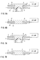
- Applying an additional pressure as shown in FIG. 6B, the boss 21 of the lead for mount 2 and the recess 22 of the base metal 7 are crashed, and the recess 22 of the base metal 7 is buried by this crashed boss 21 of the lead for mount 2. In this way, the lead for mount 2 and the base metal 7 are adhered.
- the adhesion between the lead for mount 2 and the base metal 7 can be enhanced, because the uneven sections 21, 22, 23 deform when the pressure is applied.
- a third embodiment is an example of providing a boss around the hole of the lead of the LED lamp. It should be appreciated that, in the third embodiment, the description of the structure and the adhesion method similar to the aforementioned first embodiment will be omitted, and only different structure and adhesion method shall be described.
- FIG. 7A and FIG. 7B show side views of an adhesion step of the LED lamp according to the third embodiment of the present invention.
- At least one or more boss 31 is provided around the hole 6 of the lead for mount 2. It is preferable that the tip of this boss 31 is acute. Besides, the recess 31 may be provided around the hole 6 of the base metal 7, and it is enough that it is provided on at least one of the lead for mount 2 and the base metal 7.
- the fixing pin 8 is inserted into the hole 9 of the base metal 7 through the hole 6 of the lead for mount 2.
- the boss 31 of the lead for mount 2 is crashed. In this way, the lead for mount 2 and the base metal 7 are adhered.
- the adhesion between the lead for mount 2 and the base metal 7 can be enhanced, because the boss 31 deforms when the pressure is applied.
- a fourth embodiment is an example wherein the lead ant the base metal of the LED lamp has a conical shape.
- the description of the structure and the adhesion method similar to the aforementioned first embodiment will be omitted, and only different structure and adhesion method shall be described.
- FIG. 8A and FIG. 8B show side views of an adhesion step of the LED lamp according to the fourth embodiment of the present invention.
- the hole 6a of the lead for mount 2 and the hole 9a of the base metal 7 have a conical shape like an earthenware mortar.
- the shape of the hole 6a of the lead for mount 2 is conical in a way to reduce the diameter of the hole at the side of a contact surface with the base metal 7, and the hole 9a of the base metal 7 be conical in a way to increase the diameter of the hole at the side of a contact surface with the lead for mount 2.
- the conical shape like an earthenware mortar may be applied to at least one of the lead for mount 2 and the base metal 7.
- the fixing pin 8 is inserted into the hole 9 of the base metal 7 through the hole 6 of the lead for mount 2.
- the hole 6a of the lead for mount 2 and the hole 9a of the base metal 7 are crashed and come into a close contact, and the lead for mount 2 and the base metal 7 are adhered.
- the adhesion between the lead for mount 2 and the base metal 7 can be enhanced by the conical holes 6a, 9a in the lead for mount 2 and the base metal 7, and the lead for mount 2 and the base metal 7 fit better with the fixing pin 8.
- a fifth embodiment is an example wherein the hole of the lead and the base metal of the LED lamp is a shape having a boss.
- FIG. 9 shows a plan view of the hole of the lead and the base metal according to the fifth embodiment of the present invention.
- bosses 6b, 9b projecting toward the centers of the holes 6, 9 are provided in the hole 6 of the lead for mount 2 and in the hole 9 of the base metal 7.
- the boss 6b of the lead for mount 2 and the boss 9b of the base metal 7 are provided without overlapping.
- the boss of the hole may be provided in at least one of the lead for mount 2 and the base metal 7.
- bosses 6b, 9b are provided in the holes 6, 9 of the lead for mount 2 and the base metal 7.
- the bosses 6,b, 9b of the holes 6, 9 come into contact strongly to the fixing pin, enhancing the fitting and the contact of the lead for mount 2 and the base metal 7 with the fixing pin.
- a sixth embodiment is an example wherein the diameter of the shaft portion of the fixing pin is increased from the tip to the root thereof, and a boss is provided at the shaft portion side face of the fixing pin.
- the description of the structure and the adhesion method similar to the aforementioned first embodiment will be omitted, and only different structure and adhesion method shall be described.
- FIG. 10A shows a plan view of the fixing pin according to the sixth embodiment of the present invention.
- FIG. 10B shows a side view of an LED assembly according to the sixth embodiment of the present invention.
- the diameter of the shaft portion 13a of the fixing pin 8 becoming larger than the diameter of the hole 6, 9 from the tip to be inserted to the root (head portion 12 side).
- the fixing pin 8 is adhered during a gradual enlargement of the holes 6, 9 by the shaft portion of the fixing pin 8 of large diameter. Consequently, a close contact between the lead for mount 2 and the base metal 7 is enhanced, and the fitting force between the lead for mount 2 and the base metal 7 and the fixing pin 8 is increased.
- FIG. 11A shows a plan view of another fixing pin according to the sixth embodiment.
- FIG. 11B shows a side view of another fixing pin according to the sixth embodiment.
- a cruciform boss 13b is provide on the shaft portion 13 of the fixing pin 8. It is preferable that the height of this boss 13b is lower at the tip than at the root (head portion 12 side), and the boss 13b of the root is larger than the diameter of the holes 6, 9.
- the fixing pin 8 when it is intended to insert the fixing pin 8 up to the root into the holes 6, 9 of the lead for mount 2 and the base metal 7, the fixing pin 8 is adhered during a gradual enlargement of the hole 6, 9 by the boss 13b of the fixing pin 8. Consequently, a close contact between the lead for mount 2 and the base metal 7 is enhanced, and the fitting force between the lead for mount 2 and the base metal 7 and the fixing pin 8 is increased.
- the adhesion structure and the adhesion method of the present invention are not limited to the LED lamp, but they can be applied to various semiconductor devices.
Landscapes
- Led Device Packages (AREA)
- Cooling Or The Like Of Semiconductors Or Solid State Devices (AREA)
Abstract
An LED lamp assembly according to one embodiment
of the present invention comprises a first lead (2),
an LED chip (1) mounted on the first lead (2), a second
lead (3) electrically connected to the LED chip (1),
a sealant (4) for sealing the LED chip (1) and portions
of the first and second leads (2, 3), the first and
second leads (2, 3) including first areas sealed with
the sealant (4) and second areas exposed from the
sealant (4), a metal plate (7) fixed to at least one of
the second areas of the first and second leads (2, 3),
and a pin (8) for fixing the at least one of the second
areas of the first and second leads (2, 3) and the
metal plate (7), wherein a first hole (6) is provided
on the at least one of the second areas of the first
and second leads (2, 3), a second hole (9) is provided
in an area of the metal plate (7) opposite to the first
hole (6), and the pin (8) is inserted in the first hole
(6) and the second hole (9).
Description
- The present invention relates to a light-emitting diode (LED), an LED lamp assembly and a fixing method of an LED lamp, and particularly an LED lamp of low heat resistance structure, and an LED lamp assembly in which this LED lamp is fixed to a base metal plate.
- FIG. 12 is a perspective view of an LED lamp according to the prior art. As shown in FIG. 12, an
LED lamp 100 according to the prior art has anLED chip 101 mounted on a lead formount 102, and an electrode of theLED chip 101 is connected to a lead for bonding 103 using abonding wire 105. TheLED chip 101,bonding wire 105, a portion of lead formount 102, and a portion of lead for bonding 103 are sealed with atransparent resin 104. Here, the diameter ø of the lead formount 102 and lead for bonding 103 is, for example, about 0.3 to 0.6 mm. - FIG. 13 shows a cross-sectional view of an LED lamp assembly according the related art. As shown in FIG. 13, the lead for
mount 102 and the lead for bonding 103 of theLED lamp 100 are inserted into ahole 109 of a printedboard 107, and the periphery of thishole 109 is soldered. Here, the thickness of the printedboard 107 is, for example, 1.6 µm, and the diameter ø of thehole 109 is, for example, 0.8 µm. Thereby, theLED lamp 100 is fixed mechanically and electrically to the printedboard 107 to form anLED lamp assembly 200. - However, in the above conventional
LED lamp assembly 200, heat is generated during the soldering, and this heat is absorbed in thetransparent resin 104. Thereby, thetransparent resin 104 is softened or heat expanded, theLED chip 101 is stressed, or other problems have occurred. - In addition, according to the increase of brightness of the
LED lamp 100 in recent years, a bulb by a high current driving is required. Under such a requirement, it becomes necessary to dissipate effectively the heat generation due to the electric conduction. There, the heat generation from theLED chip 101 has been released outside effectively, by making thick theleads conventional LED lamp 100. However, insuch LED lamp 100, the heat absorption amount of thetransparent resin 104 is more than a generally usedLED lamp 100, during the soldering. As a result, the problem of stress applied to theLED chip 101 described above becomes evident, thereby deteriorating the reliability of the product. - An LED lamp according to a first aspect of the present invention comprises: a first lead; an LED chip mounted on the first lead; a second lead electrically connected to the LED chip; and a sealant for sealing the LED chip and portions of the first and second leads; wherein the first and second leads comprise first areas sealed with the sealant and second areas exposed from the sealant, and a hole is provided on at least one of the second areas of the first and second leads.
- An LED lamp assembly according to a second aspect of the present invention comprises: a first lead; an LED chip mounted on the first lead; a second lead electrically connected to the LED chip; and a sealant for sealing the LED chip and portions of the first and second leads, the first and second leads comprising first areas sealed with the sealant and second areas exposed from the sealant; a metal plate fixed to at least one of the second areas of the first and second leads; and a pin for fixing the metal plate and at least one of the second areas of the first and second leads, wherein a first hole is provided in at least one of the second areas of the first and second leads, a second hole is provided in an area of the metal plate opposite to the first hole, and the pin is inserted in the first hole and the second hole.
- A fixing method of an LED lamp according to a third aspect of the present invention comprises: mounting an LED chip on a first lead, and connecting electrically a second lead with the LED chip; sealing the LED chip and portions of the first and second leads with a sealant; and inserting a pin in a first hole of the first lead and a second hole of a metal plate, expanding outward and crashing a shaft portion of the pin by press-fitting the first lead and the metal plate in the up and down direction of the pin, and fixing the first lead and the metal plate by the pin.
- This summary of the invention does not necessarily describe all necessary features so that the invention may also be a sub-combination of these described features.
- The invention can be more fully understood from the following detailed description when taken in conjunction with the accompanying drawings, in which:
- FIG. 1 is a perspective view showing an LED lamp according to a first embodiment of the present invention;
- FIG. 2 is a perspective view showing an LED lamp assembly according to the first embodiment of the present invention;
- FIG. 3 is a perspective view showing a state of inserting a fixing pin into a lead and a base metal;
- FIG. 4A is a cross section view showing an adhesion step of the LED lamp according to the first embodiment of the present invention;
- FIG. 4B is a cross section view showing an adhesion step of the LED lamp according to the first embodiment of the present invention, following FIG. 4A;
- FIG. 4C is a cross section view showing an adhesion step of the LED lamp according to the first embodiment of the present invention, following FIG. 4B;
- FIG. 5 is a graph showing a comparative example of optical output for a current of a conventional LED lamp and the LED lamp of embodiments of the present invention;
- FIG. 6A is a cross section view showing an adhesion step of an LED lamp according to a second embodiment of the present invention;
- FIG. 6B is a cross section view showing an adhesion step of the LED lamp according to the second embodiment of the present invention, following FIG. 6A;
- FIG. 7A is a cross section view showing an adhesion step of an LED lamp according to a third embodiment of the present invention;
- FIG. 7B is a cross section view showing an adhesion step of the LED lamp according to the third embodiment of the present invention, following FIG. 7A;
- FIG. 8A is a cross section view showing an adhesion step of an LED lamp according to a fourth embodiment of the present invention;
- FIG. 8B is a cross section view showing an adhesion step of the LED lamp according to the fourth embodiment of the present invention, following FIG. 8A;
- FIG. 9 is a plan view showing the shape of a hole of a lead and a base metal according to a fifth embodiment of the present invention;
- FIG. 10A is a plan view showing the shape of a fixing pin according to a sixth embodiment of the present invention;
- FIG. 10B is a cross section view of an LED assembly according to the sixth embodiment of the present invention;
- FIG. 11A is a plan view showing the shape of another fixing pin according to the sixth embodiment of the present invention;
- FIG. 11B is a side view showing the shape of another fixing pin according to the sixth embodiment of the present invention;
- FIG. 12 is a perspective view showing an LED lamp according to the prior art; and
- FIG. 13 is a cross section view of an LED assembly according to the prior art.
-
- Now, embodiments of the present invention will be described referring to the drawings.
- In a first embodiment, a first hole is proved in a lead of a light-emitting diode (LED) lamp, a second hole is provided on a base metal opposite to this first hole, and a fixing pin is inserted in the first and second holes to adhere the lead and the base metal.
- FIG. 1 is a perspective view showing an LED lamp according to the first embodiment of the present invention. As shown in FIG. 1, in an
LED lamp 10 according to the first embodiment, anLED chip 1 is mounted on a lead formount 2, and an electrode of thisLED chip 1 is connected to a lead for bonding 3 using abonding wire 5. TheLED chip 1,bonding wire 5, a portion of the lead formount 2, and a portion of the lead for bonding 3 are sealed with a sealingtransparent resin 4. Here, the sealant is not limited to the transparent resin, but for example, it may be metal, glass or the like. - In addition, a concentric circular through
hole 6 of, for example, 1.3 mm in diameter ø is provided, on a face exposed from the sealingtransparent resin 4 for lead formount 2. Thehole 6 may be provided not only on the lead formount 2 but also on the lead forbonding 3, and may be provided at least on one of the lead formount 2 and the lead forbonding 3. Besides, thehole 6 may, for example, be hexagonal, and is not limited to a concentric circular shape. - FIG. 2 is a perspective view showing an LED lamp assembly according to the first embodiment of the present invention. As shown in FIG. 2, a
base metal 7 is adhered to the lead formount 2 of the aforementioned LED lamp with a fixingpin 8. Here, a concentric circular throughhole 9 of, for example, 1.3 mm in diameter ø is provided in an area opposite to thehole 6 of the lead formount 2 in thebase metal 7. When a hole is provided on the lead forbonding 3, thebase metal 7 is also adhered to the lead for bonding 3 with the fixingpin 8. Besides, thehole 9 may, for example, be hexagonal, and is not limited to a concentric circular shape. - FIG. 3 shows a state of inserting a fixing pin into a lead and a base metal. As shown in FIG. 3, the fixing
pin 8 is inserted from thehole 6 of the lead formount 2 into thehole 9 of thebase metal 7. Then, the lead formount 2 and thebase metal 7 are adhered by press-fitting from above and under direction of the fixingpin 8, usingjigs head portion 12 of the fixingpin 8 is, for example, 2.5 mm, and the diameter ø of ashaft portion 13 of the fixingpin 8 is, for example, 1.2 mm. - FIG. 4A to FIG. 4C show side views of an adhesion step of the LED lamp. Now, an adhesion method of the LED lamp according to the first embodiment will be explained. Though FIG. 4A to FIG. 4C show an example of adhering the
base metal 7 and the lead formount 2, in case of adhering thebase metal 7 and the lead forbonding 3 also, they are adhered by a similar method. - First, as shown in FIG. 4A, a fixing
pin 8 is inserted from thehole 6 of the lead formount 2 into thehole 9 of thebase metal 7. Next, thebase metal 7 and the lead formount 2 are pinched and adhered by press-fitting from above and under direction of the fixingpin 8 usingjigs head portion 12 of the fixingpin 8 is larger than those of theholes head portion 12 of the fixingpin 8 is configured to be fixed on the surface of the lead formount 2, during the press-fitting. In addition, ahollow portion 14 is provided at the middle in theshaft portion 13 of the fixingpin 8, and a boss having a diameter slightly smaller than that of thehollow portion 14 is provided in thejig 11b. - Next, when the press-fitting is advance by the
jigs head portion 12 of he fixingpin 8 is fixed on the surface of the lead formount 2. At the same time, the boss of thejig 11b is inserted into thehollow portion 14 and pressure adhered, thereby theshaft portion 13 of the fixingpin 8 is expanded outward. Then, theshaft portion 13 of the fixingpin 8 expanded outward is crashed, in a way to sandwich the lead formount 2 and thebase metal 7, by further applying a pressure from above and under direction of the fixingpin 8. - As a result, as shown in FIG. 4C, the
hollow portion 14 of the fixingpin 8 disappears, and the lead formount 2 and thebase metal 7 are adhered. - According to the above first embodiment, the
holes mount 2 and thebase metal 7, and the fixingpin 9 is inserted into theseholes mount 2 for theLED lamp 10 is connected mechanically and electrically to thebase metal 7. Therefore, the lead formount 2 and thebase metal 7 can be made into contact over a large area. Therefore, the radiation from theLED lamp 10 at theleads LED lamp 10 is turned on can be released effectively outside. As a result, the current can be increased more than the conventional LED lamp, and theLED lamp 10 can be driven with a high current. - FIG. 5 shows a graph of a comparative example of optical output for a current of a conventional LED lamp and the LED lamp of the present invention. As shown in FIG. 5, the optical output of the conventional LED lamp lowers around 70 mA, while the optical output of the LED lamp of the present invention increases up to around 200 mA. Thus, according to the first embodiment of the present invention, the optical output of the LED lamp can be multiplied by about 3 times of the conventional one, allowing to realize an LED lamp with high brightness.
- Note that, according to the first embodiment of the present invention, the LED lamp is fixed using the fixing
pin 9. In short, it is needless to say that the problem of increase of heat absorption quantity of thetransparent resin 4 as in the related art will not occur, because the soldering is not performed. - The second embodiment is an example wherein an uneven section is provided around respective holes in the lead of the base metal and the LED lamp. In the second embodiment, the description of the structure and the adhesion method similar to the aforementioned first embodiment will be omitted, and only different structure and adhesion method shall be described.
- FIG. 6A and FIG. 6B show the side view of an adhesion step of the LED lamp according to the second embodiment of the present invention.
- In an LED lamp assembly according to the second embodiment, as shown in FIG. 6A, at least one or
more boss 21 is provided around thehole 6 of the lead formount 2. In addition, arecess 22 is provided in an area corresponding to theboss 21, around thehole 9 of thebase metal 7, and at least one ormore boss 23 is provided in an area between thisrecess 22 and thehole 9. - It is preferable that the height of the
boss 21 of the lead formount 2 is larger than the depth of therecess 22 of thebase metal 7. Also, the recess may be provided in an area corresponding to theboss 23 around thehole 6 of the lead formount 2. - Next, an adhesion method of the LED lamp according to the second embodiment will be described. First, as shown in FIG. 6A, the fixing
pin 8 is inserted into thehole 9 of thebase metal 7 through thehole 6 of the lead formount 2. Next, when pressure adhered by jigs (not shown) from above and under direction of the fixingpin 8, theboss 21 of the lead formount 2 is inserted into therecess 22 of thebase metal 7. Applying an additional pressure, as shown in FIG. 6B, theboss 21 of the lead formount 2 and therecess 22 of thebase metal 7 are crashed, and therecess 22 of thebase metal 7 is buried by this crashedboss 21 of the lead formount 2. In this way, the lead formount 2 and thebase metal 7 are adhered. - According to the aforementioned second embodiment, effects similar to the first embodiment can be obtained.
- Further, in the adhesion of the LED lamp, the adhesion between the lead for
mount 2 and thebase metal 7 can be enhanced, because theuneven sections - A third embodiment is an example of providing a boss around the hole of the lead of the LED lamp. It should be appreciated that, in the third embodiment, the description of the structure and the adhesion method similar to the aforementioned first embodiment will be omitted, and only different structure and adhesion method shall be described.
- FIG. 7A and FIG. 7B show side views of an adhesion step of the LED lamp according to the third embodiment of the present invention.
- In an LED lamp assembly according to the third embodiment, as shown in FIG. 7A, at least one or
more boss 31 is provided around thehole 6 of the lead formount 2. It is preferable that the tip of thisboss 31 is acute. Besides, therecess 31 may be provided around thehole 6 of thebase metal 7, and it is enough that it is provided on at least one of the lead formount 2 and thebase metal 7. - Next, an adhesion method of the LED lamp according to the third embodiment will be described. First, as shown in FIG. 7A, the fixing
pin 8 is inserted into thehole 9 of thebase metal 7 through thehole 6 of the lead formount 2. Next, when pressure adhered by jigs (not shown) from above and under direction of the fixingpin 8, as shown in FIG. 7B, theboss 31 of the lead formount 2 is crashed. In this way, the lead formount 2 and thebase metal 7 are adhered. - According to the aforementioned third embodiment, effects similar to the first embodiment can be obtained.
- Further, in the adhesion of the LED lamp, the adhesion between the lead for
mount 2 and thebase metal 7 can be enhanced, because theboss 31 deforms when the pressure is applied. - A fourth embodiment is an example wherein the lead ant the base metal of the LED lamp has a conical shape. In the fourth embodiment, the description of the structure and the adhesion method similar to the aforementioned first embodiment will be omitted, and only different structure and adhesion method shall be described.
- FIG. 8A and FIG. 8B show side views of an adhesion step of the LED lamp according to the fourth embodiment of the present invention.
- In an LED lamp assembly according to the fourth embodiment, as shown in FIG. 8A, the
hole 6a of the lead formount 2 and thehole 9a of thebase metal 7 have a conical shape like an earthenware mortar. Here, it is preferable that the shape of thehole 6a of the lead formount 2 is conical in a way to reduce the diameter of the hole at the side of a contact surface with thebase metal 7, and thehole 9a of thebase metal 7 be conical in a way to increase the diameter of the hole at the side of a contact surface with the lead formount 2. The conical shape like an earthenware mortar may be applied to at least one of the lead formount 2 and thebase metal 7. - Next, an adhesion method of the LED lamp according to the fourth embodiment will be described. First, as shown in FIG. 8A, the fixing
pin 8 is inserted into thehole 9 of thebase metal 7 through thehole 6 of the lead formount 2. Next, when pressure adhered by jigs (not shown) from above and under direction of the fixingpin 8, thehole 6a of the lead formount 2 and thehole 9a of thebase metal 7 are crashed and come into a close contact, and the lead formount 2 and thebase metal 7 are adhered. - According to the above fourth embodiment, effects similar to the first embodiment can be obtained.
- Further, the adhesion between the lead for
mount 2 and thebase metal 7 can be enhanced by theconical holes mount 2 and thebase metal 7, and the lead formount 2 and thebase metal 7 fit better with the fixingpin 8. - A fifth embodiment is an example wherein the hole of the lead and the base metal of the LED lamp is a shape having a boss.
- In the fifth embodiment, the description of the structure and the adhesion method similar to the aforementioned first embodiment will be omitted, and only different structure and adhesion method shall be described.
- FIG. 9 shows a plan view of the hole of the lead and the base metal according to the fifth embodiment of the present invention. As shown in FIG. 9,
bosses holes hole 6 of the lead formount 2 and in thehole 9 of thebase metal 7. Here, theboss 6b of the lead formount 2 and theboss 9b of thebase metal 7 are provided without overlapping. The boss of the hole may be provided in at least one of the lead formount 2 and thebase metal 7. - According to the above fifth embodiment, effects similar to the first embodiment can be obtained.
- Further, the
bosses holes mount 2 and thebase metal 7. Thereby, in the adhesion of the lead formount 2 and thebase metal 7, thebosses 6,b, 9b of theholes mount 2 and thebase metal 7 with the fixing pin. - A sixth embodiment is an example wherein the diameter of the shaft portion of the fixing pin is increased from the tip to the root thereof, and a boss is provided at the shaft portion side face of the fixing pin. In the sixth embodiment, the description of the structure and the adhesion method similar to the aforementioned first embodiment will be omitted, and only different structure and adhesion method shall be described.
- FIG. 10A shows a plan view of the fixing pin according to the sixth embodiment of the present invention. FIG. 10B shows a side view of an LED assembly according to the sixth embodiment of the present invention. As shown in FIG. 10A and FIG. 10B, the diameter of the
shaft portion 13a of the fixingpin 8 becoming larger than the diameter of thehole head portion 12 side). According to the structure of this fixingpin 8, when one try to insert the fixingpin 8 up to the root into theholes mount 2 and thebase metal 7, the fixingpin 8 is adhered during a gradual enlargement of theholes pin 8 of large diameter. Consequently, a close contact between the lead formount 2 and thebase metal 7 is enhanced, and the fitting force between the lead formount 2 and thebase metal 7 and the fixingpin 8 is increased. - FIG. 11A shows a plan view of another fixing pin according to the sixth embodiment. FIG. 11B shows a side view of another fixing pin according to the sixth embodiment. As shown in FIG. 11A and FIG. 11B, for example, a
cruciform boss 13b is provide on theshaft portion 13 of the fixingpin 8. It is preferable that the height of thisboss 13b is lower at the tip than at the root (head portion 12 side), and theboss 13b of the root is larger than the diameter of theholes pin 8, when it is intended to insert the fixingpin 8 up to the root into theholes mount 2 and thebase metal 7, the fixingpin 8 is adhered during a gradual enlargement of thehole boss 13b of the fixingpin 8. Consequently, a close contact between the lead formount 2 and thebase metal 7 is enhanced, and the fitting force between the lead formount 2 and thebase metal 7 and the fixingpin 8 is increased. - According to the above sixth embodiment, effects similar to the first embodiment can be obtained.
- Further, a close contact between the lead for
mount 2 and thebase metal 7 is enhanced, and the fitting force between the lead formount 2 and thebase metal 7 and the fixingpin 8 can be is increased. - The adhesion structure and the adhesion method of the present invention are not limited to the LED lamp, but they can be applied to various semiconductor devices.
Claims (23)
- An LED lamp, characterized by comprising:a first lead (2);an LED chip (1) mounted on said first lead (2);a second lead (3) electrically connected to said LED chip (1); anda sealant (4) for sealing said LED chip (1) and portions of said first and second leads (2, 3), whereinsaid first and second leads (2, 3) comprise first areas sealed with said sealant (4) and second areas exposed from said sealant (4), and a hole (6) is provided on at least one of said second areas of said first and second leads (2, 3).
- The LED lamp according to claim 1, characterized in that an uneven section (21) is provided around said hole (6) of the at least one of said first and second leads (2, 3).
- The LED lamp according to claim 1, characterized in that an acute boss (31) is provided around said hole (6) of the at least one of said first and second leads (2, 3).
- The LED lamp according to claim 1, characterized in that said hole (6a) of the at least one of said first and second leads (2, 3) has a conical shape.
- The LED lamp according to claim 1, characterized in that a boss (6b) projecting toward a center of said hole (6) is provided around said holes (6) of the at least one of said first and second leads (2, 3).
- An LED lamp assembly, characterized by comprising:a first lead (2);an LED chip (1) mounted on said first lead (2);a second lead (3) electrically connected to said LED chip (1);a sealant (4) for sealing said LED chip (1) and portions of said first and second leads (2, 3), said first and second leads (2, 3) comprising first areas sealed with said sealant (4) and second areas exposed from said sealant (4);a metal plate (7) fixed to at least one of said second areas of said first and second leads (2, 3); anda pin (8) for fixing the at least one of said second areas of said first and second leads (2, 3) and said metal plate (7), wherein,a first hole (6) is provided on the at least one of said second areas of said first and second leads (2, 3), a second hole (9) is provided in an area of said metal plate (7) opposite to said first hole (6), and said pin (8) is inserted in said first hole (6) and said second hole (9).
- The LED lamp assembly according to claim 6, characterized in that uneven sections (21, 22, 23) are provided around at least one of said first and second holes (6, 9) on a contacting face side of said metal plate (7) with the at least one of said first and second leads (2, 3).
- The LED lamp assembly according to claim 6, characterized in that an acute boss (31) is provided around at least one of said first and second holes (6, 9) on a contacting face side of said metal plate (7) with the at least one of said first and second leads (2, 3).
- The LED lamp assembly according to claim 6, characterized in that at least one of said first and second holes (6a, 9a) has a conical shape.
- The LED lamp assembly according to claim 9, characterized in thata diameter of said first hole (6a) on a contacting face side with said metal plate (7) is smaller than a diameter of said first hole (6a) on a side opposite to a contacting face with said metal plate (7), anda diameter of said second hole (9a) on a contacting face side with the at least one of said first and second leads (2, 3) is larger than a diameter of said second hole (9a) on a side opposite to a contacting face with the at least one of said first and second leads (2, 3).
- The LED lamp assembly according to claim 6, characterized in that bosses (6b, 9b) projecting toward centers of said first and second holes (6, 9) are provided around at least one of said first and second holes (6, 9).
- The LED lamp assembly according to claim 11, characterized in that said boss (6b) of said first hole (6) and said boss (9b) of said second hole (9) do not overlap.
- The LED lamp assembly according to claim 6, characterized in that said pin (8) comprises:a head portion (12); anda shaft portion (13) comprising a diameter smaller than a diameter of said head portion (12), a hollow portion (14) being provided in said shaft portion (13).
- The LED lamp assembly according to claim 6, characterized in that said pin (8) comprises:a head portion (12); anda shaft portion (13a) comprising a diameter smaller than a diameter of said head portion (12), a hollow portion (14) being provided in said shaft portion (13a), said diameter of said shaft portion (13a) becoming longer than a diameter of said first and second holes (6, 9) according to an approach to said head portion (12) from a tip section to be inserted into said first and second holes (6, 9).
- The LED lamp assembly according to claim 13, characterized in that a boss (13b) is provided on a side face of said shaft portion (13).
- A fixing method of an LED lamp characterized by comprising:mounting an LED chip (1) on a first lead (2), and connecting electrically a second lead (3) with said LED chip (1);sealing said LED chip (1) and portions of said first and second leads (2, 3) with a sealant (4); andinserting a pin (8) in a first hole (6) of said first lead (2) and a second hole (9) of a metal plate (7), expanding outward and crashing a shaft portion (13) of said pin (8) by press-fitting said first lead (2) and said metal plate (7) in up and down directions of said pin (8), and fixing said first lead (2) and said metal plate (7) by said pin (8).
- The fixing method of an LED lamp according to claim 16, characterized in thatsaid second lead (3) comprises a third hole; andsaid pin (8) is inserted into said third hole and said second hole (9), and said second lead (3) and said metal plate (7) is fixed by said pin (8).
- The fixing method of an LED lamp according to claim 16, characterized in thatuneven sections (21, 22, 23) are provided, around at least one of said first and second holes (6, 9) of a contacting face side of said metal plate (7) and said first lead (2); andsaid uneven sections (21, 22, 23) are crashed for fixing said first lead (2) and said metal plate (7) by said pin (8).
- The fixing method of an LED lamp according to claim 16, characterized in thatan acute boss (31) is provided around at least one of said first and second holes (6, 9) of a contacting face side of said metal plate (7) and said first lead (2); andsaid boss (31) is crashed to fix said first lead (2) and said metal plate (7) by said pin (8).
- The fixing method of an LED lamp according to claim 16, characterized in thatat least one of said first and second holes (6a, 9a) comprises a conical shape; andsaid first and second holes (6a, 9a) are crashed to fix said first lead (2) and said metal plate (7) by said pin (8).
- The fixing method of an LED lamp according to claim 16, characterized in thatbosses (6b, 9b) projecting toward centers of said first and second holes (6, 9) are provided around at least one of said first and second holes (6, 9); andsaid bosses (6b, 9b) are crashed to fix said first lead (2) and said metal plate (7) by said pin (8).
- The fixing method of an LED lamp according to claim 16, characterized in thatsaid pin (8) comprises a head portion (12), and a shaft portion (13a) comprising a diameter smaller than a diameter of said head portion (12),said diameter of said shaft portion (13a) becomes longer than a diameter of said first and second holes (6, 9) according to an approach to said head portion (12) from a tip section to be inserted into said first and second holes (6, 9), andduring the press-fitting, said first and second holes (6, 9) are enlarged gradually by said shaft portion (13a) to fix said first lead (2) and said metal plate (7) by said pin (8).
- The fixing method of an LED lamp according to claim 16, characterized in thatsaid pin (8) comprises a head portion (12) and a shaft portion (13) comprising a diameter smaller than a diameter of said head portion (12) and provided with a boss (13b) on a side face thereof; andsaid boss (13b) is crashed to fix said first lead (2) and said metal plate (7) by said pin (8).
Applications Claiming Priority (2)
| Application Number | Priority Date | Filing Date | Title |
|---|---|---|---|
| JP2000291908A JP2002111067A (en) | 2000-09-26 | 2000-09-26 | LED lamp and LED lamp assembly |
| JP2000291908 | 2000-09-26 |
Publications (1)
| Publication Number | Publication Date |
|---|---|
| EP1191609A2 true EP1191609A2 (en) | 2002-03-27 |
Family
ID=18774923
Family Applications (1)
| Application Number | Title | Priority Date | Filing Date |
|---|---|---|---|
| EP01308136A Withdrawn EP1191609A2 (en) | 2000-09-26 | 2001-09-25 | LED lamp, LED lamp assembly and fixing method of an LED lamp |
Country Status (3)
| Country | Link |
|---|---|
| US (1) | US20020036464A1 (en) |
| EP (1) | EP1191609A2 (en) |
| JP (1) | JP2002111067A (en) |
Families Citing this family (8)
| Publication number | Priority date | Publication date | Assignee | Title |
|---|---|---|---|---|
| DE10255932A1 (en) * | 2002-11-29 | 2004-06-17 | Osram Opto Semiconductors Gmbh | Optoelectronic component |
| WO2005000363A2 (en) * | 2003-06-16 | 2005-01-06 | Cerionx, Inc. | Atmospheric pressure non-thermal plasma device to clean and sterilize the surface of probes, cannulas, pin tools, pipettes and spray heads |
| WO2007099796A1 (en) * | 2006-02-22 | 2007-09-07 | Nippon Sheet Glass Company, Limited. | Light emitting unit, lighting apparatus and image reading apparatus |
| KR101249989B1 (en) * | 2006-11-07 | 2013-04-01 | 삼성디스플레이 주식회사 | Light source unit, backlight unit and liquid crystal display having the same |
| JP4924090B2 (en) * | 2007-02-23 | 2012-04-25 | 日亜化学工業株式会社 | Light emitting device |
| TWI363432B (en) * | 2007-02-26 | 2012-05-01 | Everlight Electronics Co Ltd | A structure of a light emitting diode and a method to assemble thereof |
| WO2012101815A1 (en) * | 2011-01-28 | 2012-08-02 | パイオニア株式会社 | Light emitting module and method of producing light emitting module |
| CN104505452A (en) * | 2014-11-14 | 2015-04-08 | 浙江英特来光电科技有限公司 | Reflow soldering LED (Light Emitting Diode) lamp filament |
Family Cites Families (1)
| Publication number | Priority date | Publication date | Assignee | Title |
|---|---|---|---|---|
| DE19715093C2 (en) * | 1997-04-11 | 1999-05-27 | Hermann Stahl Gmbh | Carrier for mechanical holding and electrical connection of electronic components, in particular light emitting diodes, and method for electrically conductive connection of the components on a carrier |
-
2000
- 2000-09-26 JP JP2000291908A patent/JP2002111067A/en active Pending
-
2001
- 2001-09-24 US US09/962,283 patent/US20020036464A1/en not_active Abandoned
- 2001-09-25 EP EP01308136A patent/EP1191609A2/en not_active Withdrawn
Also Published As
| Publication number | Publication date |
|---|---|
| US20020036464A1 (en) | 2002-03-28 |
| JP2002111067A (en) | 2002-04-12 |
Similar Documents
| Publication | Publication Date | Title |
|---|---|---|
| US7557384B2 (en) | Semiconductor light emitting device and semiconductor light emitting unit | |
| US8703513B2 (en) | Method for manufacturing light emitting apparatus, light emitting apparatus, and mounting base thereof | |
| US6060729A (en) | Light-emitting device | |
| US20030098459A1 (en) | Light emitting diode device | |
| US20070120139A1 (en) | Semiconductor light emitting device | |
| JP2010199565A (en) | Method of manufacturing light-emitting diode | |
| KR950021448A (en) | Semiconductor device and manufacturing method thereof | |
| JPH05243457A (en) | Semiconductor element structure, metallic plate producing method and current transmitting terminal producing method | |
| US20020036464A1 (en) | Led lamp, led lamp assembly and fixing method of an led lamp | |
| JP2007096079A (en) | Semiconductor light emitting device | |
| JP2010093066A (en) | Light-emitting device | |
| JP2001144334A (en) | Optical semiconductor device and forming method therefor | |
| KR100255000B1 (en) | Capillary for using in a wire bonding apparatus | |
| US6617617B2 (en) | Light-emitting diode | |
| JP2010045167A (en) | Semiconductor device | |
| WO2010067701A1 (en) | Light-emitting device, light-emitting device module, and light-emitting device manufacturing method | |
| JPH02246359A (en) | Semiconductor device | |
| WO2008139981A1 (en) | Light emitting device and package assembly for light emitting device | |
| JPH1117050A (en) | Circuit board and method of manufacturing circuit board | |
| JP2009076516A (en) | Lighting device | |
| JP4389263B2 (en) | Manufacturing method of semiconductor light emitting device | |
| US20050179123A1 (en) | Dual-sided substrate integrated circuit package including a leadframe having leads with increased thickness | |
| US8053282B2 (en) | Mounting structure of component of lighting device and method thereof | |
| JP4882284B2 (en) | LED device and manufacturing method thereof | |
| JP2007067284A (en) | LED device |
Legal Events
| Date | Code | Title | Description |
|---|---|---|---|
| PUAI | Public reference made under article 153(3) epc to a published international application that has entered the european phase |
Free format text: ORIGINAL CODE: 0009012 |
|
| 17P | Request for examination filed |
Effective date: 20011008 |
|
| AK | Designated contracting states |
Kind code of ref document: A2 Designated state(s): AT BE CH CY DE DK ES FI FR GB GR IE IT LI LU MC NL PT SE TR |
|
| AX | Request for extension of the european patent |
Free format text: AL;LT;LV;MK;RO;SI |
|
| STAA | Information on the status of an ep patent application or granted ep patent |
Free format text: STATUS: THE APPLICATION HAS BEEN WITHDRAWN |
|
| 18W | Application withdrawn |
Effective date: 20070828 |