EP1191581A1 - Electrostatic chuck and treating device - Google Patents
Electrostatic chuck and treating device Download PDFInfo
- Publication number
- EP1191581A1 EP1191581A1 EP00929866A EP00929866A EP1191581A1 EP 1191581 A1 EP1191581 A1 EP 1191581A1 EP 00929866 A EP00929866 A EP 00929866A EP 00929866 A EP00929866 A EP 00929866A EP 1191581 A1 EP1191581 A1 EP 1191581A1
- Authority
- EP
- European Patent Office
- Prior art keywords
- electrostatic chuck
- insulative substrate
- dielectric layer
- insulative
- substrate
- Prior art date
- Legal status (The legal status is an assumption and is not a legal conclusion. Google has not performed a legal analysis and makes no representation as to the accuracy of the status listed.)
- Granted
Links
Images


Classifications
-
- B—PERFORMING OPERATIONS; TRANSPORTING
- B23—MACHINE TOOLS; METAL-WORKING NOT OTHERWISE PROVIDED FOR
- B23Q—DETAILS, COMPONENTS, OR ACCESSORIES FOR MACHINE TOOLS, e.g. ARRANGEMENTS FOR COPYING OR CONTROLLING; MACHINE TOOLS IN GENERAL CHARACTERISED BY THE CONSTRUCTION OF PARTICULAR DETAILS OR COMPONENTS; COMBINATIONS OR ASSOCIATIONS OF METAL-WORKING MACHINES, NOT DIRECTED TO A PARTICULAR RESULT
- B23Q3/00—Devices holding, supporting, or positioning work or tools, of a kind normally removable from the machine
- B23Q3/15—Devices for holding work using magnetic or electric force acting directly on the work
-
- H—ELECTRICITY
- H10—SEMICONDUCTOR DEVICES; ELECTRIC SOLID-STATE DEVICES NOT OTHERWISE PROVIDED FOR
- H10P—GENERIC PROCESSES OR APPARATUS FOR THE MANUFACTURE OR TREATMENT OF DEVICES COVERED BY CLASS H10
- H10P72/00—Handling or holding of wafers, substrates or devices during manufacture or treatment thereof
- H10P72/50—Handling or holding of wafers, substrates or devices during manufacture or treatment thereof for positioning, orientation or alignment
-
- B—PERFORMING OPERATIONS; TRANSPORTING
- B23—MACHINE TOOLS; METAL-WORKING NOT OTHERWISE PROVIDED FOR
- B23Q—DETAILS, COMPONENTS, OR ACCESSORIES FOR MACHINE TOOLS, e.g. ARRANGEMENTS FOR COPYING OR CONTROLLING; MACHINE TOOLS IN GENERAL CHARACTERISED BY THE CONSTRUCTION OF PARTICULAR DETAILS OR COMPONENTS; COMBINATIONS OR ASSOCIATIONS OF METAL-WORKING MACHINES, NOT DIRECTED TO A PARTICULAR RESULT
- B23Q3/00—Devices holding, supporting, or positioning work or tools, of a kind normally removable from the machine
- B23Q3/15—Devices for holding work using magnetic or electric force acting directly on the work
- B23Q3/154—Stationary devices
-
- H—ELECTRICITY
- H02—GENERATION; CONVERSION OR DISTRIBUTION OF ELECTRIC POWER
- H02N—ELECTRIC MACHINES NOT OTHERWISE PROVIDED FOR
- H02N13/00—Clutches or holding devices using electrostatic attraction, e.g. using Johnson-Rahbek effect
-
- H—ELECTRICITY
- H10—SEMICONDUCTOR DEVICES; ELECTRIC SOLID-STATE DEVICES NOT OTHERWISE PROVIDED FOR
- H10P—GENERIC PROCESSES OR APPARATUS FOR THE MANUFACTURE OR TREATMENT OF DEVICES COVERED BY CLASS H10
- H10P72/00—Handling or holding of wafers, substrates or devices during manufacture or treatment thereof
- H10P72/70—Handling or holding of wafers, substrates or devices during manufacture or treatment thereof for supporting or gripping
- H10P72/72—Handling or holding of wafers, substrates or devices during manufacture or treatment thereof for supporting or gripping using electrostatic chucks
- H10P72/722—Details of electrostatic chucks
Definitions
- the present invention relates to a processing apparatus of an insulative substrate for use in a PDP (plasma display) manufacturing apparatus, a master writer manufacturing apparatus for a DVD (digital video (or versatile) disc), a substrate processing apparatus for a hard disc manufacturing apparatus, a reticle fixing apparatus in an EB (electron beam) exposure apparatus, and a CVD, etching or sputtering apparatus for manufacturing elements to be formed on SOS (silicon on sapphire) and SOI (silicon on insulator) wafers.
- PDP plasma display
- DVD digital video (or versatile) disc
- a substrate processing apparatus for a hard disc manufacturing apparatus a reticle fixing apparatus in an EB (electron beam) exposure apparatus
- CVD etching or sputtering apparatus for manufacturing elements to be formed on SOS (silicon on sapphire) and SOI (silicon on insulator) wafers.
- a material to be processed is a glass substrate which shows electrically insulative characteristic. Therefore, in the conventional art, since it is impossible to electrostatically attract these substrates within a vacuum, they are flatly placed on a stage in the manufacturing apparatus thereof or they are fixed with a mechanical mechanism.
- a reticle of the EB exposure apparatus is comprised of quartz which also shows electrically insulative characteristic. Therefore, conventionally, the reticle is fixed under a vacuum with a mechanical mechanism.
- SOS wafers and SOI wafers attracting attention as next-generation alternatives to silicon wafers, show electrically insulative characteristic with regards to the surface by which they are mounted on a stage. Therefore, conventionally, it is impossible to apply a fixing method using an electrostatic chuck in the manufacturing apparatus for forming devices on these wafers.
- a means and a principle of electrostatically attracting a silicon wafer are disclosed, for example, in Japanese Patent Application Laid-Open No. Hei 5-63062 (1993), however it is impossible to electrostatically attract an insulative substrate in accordance with the principle.
- the temperature control in the process comes to be very important.
- the temperature control is conducted in the process using an electrostatic chuck.
- an electrostatic chuck with which an insulative substrate can be electrostatically attracted, and a processing apparatus using such an electrostatic chuck are desired.
- an electrostatic chuck which can electrostatically attract an insulative substrate, such as a glass substrate, and a heating/cooling apparatus and a temperature controller apparatus for an insulative substrate using such an electrostatic chuck.
- the distance between a plurality of electrodes which are provided on one side of a dielectric constructing the electrostatic chuck is made small, and the thickness of the dielectric is made thin.
- a potential difference is given between the electrodes so as to form an ununiform electric field upon an attracting surface of the dielectric.
- An insulative material to be processed being within the ununiform electric field is partially polarized, and generates gradient force that is attracted in the direction being strong in the strength of the electric field.
- the gradient force is expressed by F ⁇ ⁇ ⁇ grad E 2 , wherein F is gradient force, ⁇ an inductive polarization charge, and E an electric field.
- the present invention utilizes this effect.
- an electrostatic chuck for attracting an insulative substrate by specifying the shape and the properties of a dielectric, and the shapes of electrodes.
- a heating/cooling apparatus and a temperature controlling system comprising the electrostatic chuck mentioned above, a plate in which a flow passage is formed to supply or diffuse heat generated in the process or heat to be supplied to an insulative substrate by a medium, and a gas supply conduit for supplying a gas which is enclosed within a space defined between the insulative substrate and the attracting surface of a dielectric for adjusting heat transmission therebetween, wherein the pressure of the enclosed gas can be adjusted by the temperature of the insulative substrate and thereby the temperature can be adjusted to a predetermined value.
- FIG. 1 is a plane view showing an example of an electrostatic chuck according to the present invention and FIG. 2 is a cross-sectional view thereof.
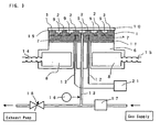
- FIG. 3 is a cross-sectional view showing the condition of attracting an insulative substrate 10 by an electrostatic chuck 1.
- an attracting force is generated between the insulative substrate 10 and the electrostatic chuck 1, thereby attracting the insulative substrate 10 at protrusions 2 and an outer peripheral seal ring 3 (hereinafter, collectively referred to as a "solid-body contact portion").
- the electrostatic chuck 1 is connected through a connector portion 11 onto a metal plate 6, and heating/cooling is conducted to the electrostatic chuck 1 by passing a medium through a medium flow passage 8 which is provided within the metal plate 6.
- FIGS. 4 through 6 show various examples of a pattern of the electrodes 7 which are formed on one surface of the dielectric.
- radio-frequency current which is used in a plasma process for SOS or SOI wafers can be dispersed into each of the electrodes, thereby enabling to reduce a load for each of electrically conductive terminals or the like.
- Gas is supplied through a gas supply conduit 13 from a gas supply opening 5 and enclosed within a gas enclosure portion 9.
- grooves 4 are formed on the surface of the electrostatic chuck 1.
- heat transmission is conducted between the insulative substrate 10 and the electrostatic chuck 1.
- signal voltage is outputted in the range of 0 to 10 V by pressure.
- a pressure control valve 17 is provided, and opened and closed by comparing the signal voltage of the gas pressure gauge 16 with a preset value, thereby enabling to adjust the pressure of the gas to the preset value.
- the electrostatically attracting force will correspond to the tensile strength of 300g/cm 2 in the case where the measured value is 300g/5cm 2 .
- This value corresponds to about 30 kPa, which is enough to attract the material to be attracted within a vacuum chamber.
- it was set to be 1 mm in the width of the electrode, 1 mm in the distance between the electrodes, and 0.5 mm in the thickness of the dielectric.
- 1A through 1D and 2 show the electrostatically attracting force in a case of varying the resistivity of the dielectric substrate.
- the resistivity does not have an influence to the electrostatic force very much; however, it is preferable that the resistivity be less than or equal to 10 13 ⁇ cm, which creates larger electrostatically attracting force.
- 1F and 1G show the electrostatically attracting force in a case of varying the surface roughness of the dielectric substrate. Compared to 1B, it is preferable that the surface roughness be less than or equal to Ra 0.25 ⁇ m.
- the surface roughness of the material to be attracted used in the present embodiment is less than or equal to Ra 0.1 ⁇ m, except for the substrate of polycrystal alumina in 1P.
- 1B and 2 through 6 show the electrostatically attracting force in a case of varying the dielectric material.
- the resistivity rather than the relative dielectric constant has a larger relationship to the electrostatically attracting force.
- the dielectric material the most stable and large attracting force can be achieved by using ceramic sintered body obtained by adding chromium oxide and/or titanium oxide to alumina, and the material obtained by adding a sinter assisting material thereto.
- 1B and 1H through 1N show the electrostatically attracting force in a case of varying the kind of the material to be attracted. The result shows that different insulative materials can be electrostatically attracted, and that the larger the relative dielectric constant of the material to be attracted, the larger the force.
- a substrate of polycrystal alumina is used as a material to be attracted, the surface roughness thereof is varied, and then the electrostatically attracting force is measured.
- the result shows that the sufficient force can be obtained if the surface roughness of the material to be attracted is around Ra 0.4 ⁇ m Therefore, when the relative dielectric constant of the material to be attracted becomes large, the surface roughness of the material to be attracted can be degraded.
- Table 2 shows the relationship between the electrostatically attracting force with respect to a glass substrate and the applied voltage (10 kV) in a case of using ceramic sintered body obtained by adding chromium oxide and/or titanium oxide to alumina, and varying the pattern of the electrodes in the electrostatic chuck according to the present invention. No.
- the maximum electrostatically attracting force can be obtained when the thickness of the dielectric is 0.3 mm, and there is a tendency that the thinner the thickness thereof, the larger the electrostatically attracting force.
- both of the width and the distance are equal to or greater than 0.5 mm, the electrostatically attracting is available.
- sufficient insulation between the electrodes cannot be achieved if the distance between the electrodes is smaller than 0.5 mm. As a result of this, there are cases where the electrostatically attracting cannot be obtained.
- the electrostatically attracting force can hardly be obtained.
- the voltage applied is raised to 10 kV. It is expected that the sufficient force can be obtained even if the distance between the electrodes is 2 mm, by applying voltage being larger than that.
- the thickness of the dielectric in the range of 0.3 to 2.0 mm, the distance between the electrodes in the range of 0.5 to 1.0 mm, the width of the electrode in the range of 0.5 to 4.0 mm, and the resistivity of the dielectric to be less than or equal to 10 13 ⁇ cm. It is more preferable that the thickness of the dielectric be in the range of 0.3 to 1.0 mm, the distance between the electrodes in the range of 0.5 to 1.0 mm, the width of the electrode in the range of 0.5 to 1.0 mm, and the resistivity of the dielectric to be less than or equal to 10 13 ⁇ cm.
- FIGS. 7 through 9 are graphs showing data on thermal attraction experiments and cooling experiments on an insulative substrate.
- a glass substrate i.e., a low alkaline glass
- the insulative substrate 10 is used as the insulative substrate 10.
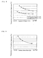
- FIG. 7 is a graph showing the relationship between the temperature of an insulative substrate and the pressure of the gas for heating/cooling to be supplied into a space between the insulative substrate and the attracting surface of the dielectric, in which the insulative substrate is positioned in a substrate heating/cooling apparatus which is provided within a vacuum chamber.
- the thermal characteristic in a case where a heat flow of 2W/cm 2 is supplied from the upper surface of the insulative substrate 10 is shown by expressing the pressure of the above-mentioned gas on x-axis and the surface temperature of the insulative substrate 10 on y-axis.
- This graph shows that the temperature of the insulative substrate 10 can be controlled by varying the gas pressure enclosed in a gas enclosure portion 9. He gas is mainly used in the present experiment; however, the same heating/cooling effect can be obtained by using Ar or N 2 .
- the height of the protrusions 2 In order to increase efficiency of the heating/cooling by supplying higher pressure, it is necessary to make the height of the protrusions 2 on the attracting surface of the dielectric 19 low and thereby bring the pressure of the gas into the region of a molecular flow.
- the height of the protrusions 2 may be set to be less than or equal to 5 ⁇ m
- the formation of the grooves 4 is important as well as the protrusions 2.
- the effect can be achieved when they are formed in a radial pattern from the gas supply opening, and they are equal to or greater than 1.0 mm in the width and equal to or greater than 50 ⁇ m in the depth.
- the width is equal to or greater than 1.5 mm and the depth is equal to or greater than 250 ⁇ m, and thereby the time until the pressure distribution in the shape comes to be uniform is less than or equal to 5 seconds.
- the effect can be further increased if the grooves are formed in a concentric pattern as well as a radial pattern.
- the experiment result shows that the temperature of the insulative substrate 10 is varied by varying the ratio of a contact area.
- the contact area ratio it is necessary to vary the number and the diameter of the protrusions.
- the diameter of the protrusions in the present embodiment is 5 mm, and the width of the seal ring is 4 mm.
- the number of the protrusions is converted from the contact area ratio.
- the protrusions are distributed upon the surface of the electrostatic chuck in the substantially equal position with regards to each other.
- the present embodiment shows that large heating/cooling effect on the insulative substrate 10 can be obtained by enclosing the high gas pressure of 6664 Pa (50 Torr) in the gas enclosure portion 9.
- the electrostatic chuck generate a large attracting force.
- the gas pressure of 1333 Pa (10 Torr) in a case where the contact area ratio is 20 % theoretically, the attracting force of at least 13 g/cm 2 is required. Therefore, the electrostatic chuck having a very large attracting force is required.
- Ceramic sintered body comprised of mainly alumina, and chromium oxide (Cr 2 O 3 ), titanium oxide (TiO 2 ), and a sinter assisting material added thereto in an appropriate amount.
- the attracting force in this material is about 300 g/5cm 2 under application of 10 KV, which is the same as 1A - 1C mentioned above, and the tensile strength in the vertical direction can be assumed to be 300 g/cm 2 . Even if the contact area ratio is 20%, it can be ensured that the attracting force is equal to or greater than 60 g/cm 2 . Therefore, it is possible to sufficiently attract the insulative substrate.
- a low alkaline glass is used as the insulative substrate 10 in the present embodiment; however, the electrostatic chuck according to the present invention can in general also be applied to other electrical insulative substrates and/or films.
- the signal outputted from the measurement apparatus is compared with a predetermined value, and thereby the temperature of the material to be attracted can easily be controlled.
- the temperature of the insulative substrate cannot directly be measured, it is possible to maintain the temperature of the insulative substrate based on a data base in which the gas pressure, the applied voltage, the ratio of the solid-body contact area, the supplied thermal energy, the flow rate of the medium, the temperature of the medium, or the like are compiled in advance and linked together.
- the heating/cooling apparatus for an insulative substrate according to the present embodiment within a reaction chamber, it is possible to easily control the temperature in a semiconductor manufacturing process, in particular, in a plasma CVD for an SOS or SOI, a plasma etching, a sputtering, or the like.
- a material to be processed can be attracted with the electrostatic chuck even if it is an insulative material, it is possible to easily heat/cool the insulative substrate with the heating/cooling apparatus in which the electrostatic chuck is installed, and thereby it is possible to control the temperature of the insulative substrate at a predetermined value.
Landscapes
- Engineering & Computer Science (AREA)
- Mechanical Engineering (AREA)
- Container, Conveyance, Adherence, Positioning, Of Wafer (AREA)
- Jigs For Machine Tools (AREA)
Abstract
Description
| No. | Scope Of Present Invention | Dielectric Material | Material To Be Attracted | Thickness (µm) | Resistivity Of Dielectric (Ωcm) | Relative Dielectric Constant Of Dielectric | Surface Roughness Of Dielectric Ra(µm) | Electrostatically Attracting Force (g/5cm2) |
| 1A | ○ | Al2O3-Cr2O3-TiO2 Ceramic Sintered Body | Low Alkaline Glass, Substrate Thickness 0.6 mm, Relative Dielectric Constant 5 | 500 | 1010 | 9 | 0.25 | >300 |
| 1B | ○ | Al2O3-Cr2O3-TiO2 Ceramic Sintered Body | Low Alkaline Glass, Substrate Thickness 0.6 mm | 500 | 1011 | 9 | 0.25 | >300 |
| 1C | ○ | Al2O3-Cr2O3-TiO2 Ceramic Sintered Body | Low Alkaline Glass, Substrate Thickness 0.6 mm | 500 | 1012 | 9 | 0.25 | >300 |
| 1D | ○ | Al2O3-Cr2O3-TiO2 Ceramic Sintered Body | Low Alkaline Glass, Substrate Thickness 0.6 mm | 500 | 1013 | 9 | 0.25 | >300 |
| 1E | ○ | Al2O3-Cr2O3-TiO2 Ceramic Sintered Body | Low Alkaline Glass, Substrate Thickness 0.6 | 1000 | 1011 | 9 | 0.25 | >300 |
| 1F | ○ | Al2O3-Cr2O3-TiO2 Ceramic Sintered Body | Low Alkaline Glass, Substrate Thickness 0.6 mm | 500 | 1011 | 9 | 0.4 | 250 |
| 1G | ○ | Al2O3-Cr2O3-TiO2 Ceramic Sintered Body | Low Alkaline Glass, Substrate Thickness 0.6 mm | 500 | 1011 | 9 | 1.0 | 50 |
| 1H | ○ | Al2O3-Cr2O3-TiO2 Ceramic Sintered Body | Quartz Glass, | 500 | 1011 | 9 | 0.25 | >300 |
| 1I | ○ | Al2O3-Cr2O3-TiO2 Ceramic Sintered Body | Sapphire, Thickness 0.5 mm, Relative Dielectric Constant 10 | 500 | 1011 | 9 | 0.25 | >300 |
| 1J | ○ | Al2O3-Cr2O3-TiO2 Ceramic Sintered Body | High Dielectric Substrate (Relative Dielectric Constant 120, Thickness 0.5 mm) | 500 | 1011 | 9 | 0.25 | >300 |
| 1K | ○ | Al2O3-Cr2O3-TiO2 Ceramic Sintered Body | High Dielectric Substrate (Relative Dielectric Constant 10,000, Thickness 0.5 mm) | 500 | 1011 | 9 | 0.25 | >300 |
| 1L | ○ | Al2O3-Cr2O3-TiO2 Ceramic Sintered Body | Polyimide Film ( | 500 | 1011 | 9 | 0.25 | 100 |
| 1M | ○ | Al2O3-Cr2O3-TiO2 Ceramic Sintered Body | SOI Wafer | 500 | 1011 | 9 | 0.25 | >300 |
| 1N | ○ | Al2O3-Cr2O3-TiO2 Ceramic Sintered Body | sos wafer | 500 | 1011 | 9 | 0.25 | >300 |
| 1O | ○ | Al2O3-Cr2O3-TiO2 Ceramic Sintered Body | Polycrystal Alumina Substrate, Thickness 0.6 mm, Surface Roughness Ra 0.1 µm, Relative | 500 | 1011 | 9 | 0.25 | >300 |
| 1P | ○ | Al2O3-Cr2O3-TiO2 Ceramic Sintered Body | Polycrystal Alumina Substrate, Thickness 0.6 mm, Surface Roughness Ra 0.4 µm, Relative Dielectric Constant 10 | 500 | 1011 | 9 | 0.25 | >300 |
| 2 | ○ | Al2O3 Ceramic Sintered Body | Low Alkaline Glass, Substrate Thickness 0.6 mm | 500 | 1015 | 9 | 0.1 | 100 |
| 3 | ○ | BaTiO3 Ceramic Sintered Body | Low Alkaline Glass, Substrate Thickness 0.6 mm | 500 | 1011 | 120 | 0.1 | 150 |
| 4 | ○ | BaTiO3 Ceramic Sintered Body | Low Alkaline Glass, Substrate Thickness 0.6 mm | 500 | 1010 | 10,000 | 0.2 | 100 |
| 5 | ○ | BaTiO3 Ceramic Sintered | Low Alkaline Glass, Substrate Thickness | 500 | 109 | 20,000 | 0.3 | 100 |
| Body | 0.6 | |||||||
| 6 | ○ | SiC Ceramic Sintered Body | Low Alkaline Glass, Substrate Thickness 0.6 mm | 500 | 1010 | 120 | 0.1 | >300 |
| 7 | ○ | Silicon Rubber | Low Alkaline Glass, Substrate Thickness 0.6 mm | 500 | 1010 | 3 | 0.4 | 150 |
| No. | Scope Of Present Invention | Thickness of Dielectric (µm) | Width of Electrodes (mm) | Distance Between Electrodes (mm) | Electrostatically Attracting Force (g/5cm2) 10KV |
| 7 | × | 300 | 0.3 | 0.3 | Break down |
| 8 | ○ | 300 | 0.5 | 0.5 | Break down |
| 9 | ○ | 300 | 0.7 | 0.7 | >300 |
| 10 | ○ | 300 | 1.0 | 1.0 | >300 |
| 11 | ○ | 300 | 2.0 | 2.0 | 180 |
| 12 | × | 300 | 3.0 | 3.0 | 30 |
| 13 | ○ | 300 | 0.5 | 1.0 | >300 |
| 14 | ○ | 300 | 0.5 | 1.5 | 200 |
| 15 | ○ | 300 | 2.0 | 1.0 | 250 |
| 16 | ○ | 300 | 4.0 | 1.0 | 120 |
| 17 | × | 300 | 6.0 | 1.0 | 30 |
| 18 | × | 400 | 0.3 | 0.3 | Breakdown |
| 19 | ○ | 400 | 0.5 | 0.5 | >300 |
| 20 | ○ | 400 | 0.7 | 0.7 | >300 |
| 21 | ○ | 400 | 1.0 | 1.0 | >300 |
| 22 | ○ | 400 | 2.0 | 2.0 | 120 |
| 23 | × | 400 | 3.0 | 3.0 | 30 |
| 24 | ○ | 400 | 0.5 | 1.0 | >300 |
| 25 | ○ | 400 | 0.5 | 1.5 | 200 |
| 26 | ○ | 400 | 2.0 | 1.0 | 200 |
| 27 | ○ | 400 | 4.0 | 1.0 | 100 |
| 28 | × | 400 | 6.0 | 1.0 | 20 |
| 29 | × | 500 | 0.3 | 0.3 | Break down |
| 30 | ○ | 500 | 0.5 | 0.5 | Break down |
| 31 | ○ | 500 | 0.7 | 0.7 | >300 |
| 32 | ○ | 500 | 1.0 | 1.0 | 280 |
| 33 | ○ | 500 | 2.0 | 2.0 | 100 |
| 34 | × | 500 | 3.0 | 3.0 | 20 |
| 35 | ○ | 500 | 0.5 | 1.0 | >300 |
| 36 | ○ | 500 | 0.5 | 1.5 | 200 |
| 37 | ○ | 500 | 2.0 | 1.0 | 165 |
| 38 | ○ | 500 | 4.0 | 1.0 | 45 |
| 39 | × | 500 | 6.0 | 1.0 | 25 |
| 40 | × | 700 | 0.3 | 0.3 | Break down |
| 41 | ○ | 700 | 0.5 | 0.5 | 240 |
| 42 | ○ | 700 | 0.7 | 0.7 | 240 |
| 43 | ○ | 700 | 1.0 | 1.0 | 220 |
| 44 | ○ | 700 | 2.0 | 2.0 | 90 |
| 45 | × | 700 | 3.0 | 3.0 | 20 |
| 46 | ○ | 700 | 0.5 | 1.0 | 260 |
| 47 | ○ | 700 | 0.5 | 1.5 | 150 |
| 48 | ○ | 700 | 2.0 | 1.0 | 140 |
| 49 | ○ | 700 | 4.0 | 1.0 | 50 |
| 50 | × | 700 | 6.0 | 1.0 | 20 |
| 51 | × | 1,000 | 0.3 | 0.3 | Break down |
| 52 | ○ | 1,000 | 0.5 | 0.5 | 200 |
| 53 | ○ | 1,000 | 0.7 | 0.7 | 200 |
| 54 | ○ | 1,000 | 1.0 | 1.0 | 180 |
| 55 | ○ | 1,000 | 2.0 | 2.0 | 70 |
| 56 | × | 1,000 | 3.0 | 3.0 | 20 |
| 57 | ○ | 1,000 | 0.5 | 1.0 | 220 |
| 58 | ○ | 1,000 | 0.5 | 1.5 | 120 |
| 59 | ○ | 1,000 | 2.0 | 1.0 | 120 |
| 60 | ○ | 1,000 | 4.0 | 1.0 | 30 |
| 61 | × | 1,000 | 6.0 | 1.0 | 10 |
| 62 | × | 2,000 | 0.3 | 0.3 | Break down |
| 63 | ○ | 2,000 | 0.5 | 0.5 | 170 |
| 64 | ○ | 2,000 | 0.7 | 0.7 | 130 |
| 65 | ○ | 2,000 | 1.0 | 1.0 | 100 |
| 66 | ○ | 2,000 | 2.0 | 2.0 | 10 |
| 67 | × | 2,000 | 3.0 | 3.0 | 10 |
| 68 | ○ | 2,000 | 0.5 | 1.0 | 120 |
| 69 | ○ | 2,000 | 0.5 | 1.5 | 30 |
| 70 | ○ | 2,000 | 2.0 | 1.0 | 70 |
| 71 | ○ | 2,000 | 4.0 | 1.0 | 30 |
| 72 | × | 2,000 | 6.0 | 1.0 | 10 |
Claims (16)
- An electrostatic chuck for attracting an insulative substrate, comprising:a dielectric layer having a first surface which is made an attracting surface for attracting an insulative substrate, and a second surface on which are provided a plurality of electrodes;an insulative support base plate for fixing said dielectric layer thereon;a plurality of electrically conductive terminals which are provided on said insulative support base plate; anda means for electrically connecting said electrodes which are provided on said dielectric layer and said electrically conductive terminals.
- An electrostatic chuck according to claim 1, wherein the resistivity of said dielectric layer is less than or equal to 1013 Ω cm at room temperature.
- An electrostatic chuck according to claim 1 or 2, wherein the thickness of said dielectric layer is less than or equal to 2 mm.
- An electrostatic chuck according to any one of claims 1 - 3, wherein said dielectric layer is comprised of ceramic obtained by adding chromium oxide and/or titanium oxide to alumina as a main raw material and firing.
- An electrostatic chuck according to any one of claims 1 - 4, wherein the attracting surface of said dielectric layer has grooves, protrusions and an outer peripheral seal ring.
- An electrostatic chuck according to any one of claims 1 - 5, wherein said plurality of electrodes which are provided on the second surface of said dielectric layer form a pair, the width of each electrode is less than or equal to 4 mm, the distance between the electrodes is less than or equal to 2 mm, and each electrode is intricate in a comb-tooth shape.
- An electrostatic chuck according to any one of claims 1 - 5, wherein said plurality of electrodes which are provided on the second surface of said dielectric layer form a plurality of pairs, the width of each electrode is less than or equal to 4 mm, the distance between the electrodes is respectively less than or equal to 2 mm, and each electrode is intricate in a comb-tooth shape.
- An electrostatic chuck according to any one of claims 1 - 7, wherein said insulative support base plate is comprised of a material having a larger resistivity than that of said dielectric layer.
- An electrostatic chuck according to any one of claims 1 - 8, wherein said electrically conductive terminals are formed through any one of hard solder, soft solder, and a conductive adhesive.
- An electrostatic chuck according to any one of claims 1 - 9, wherein said means for electrically connecting is any one of a conductive wire, a conductive rod, and filling of conductive resin or solder.
- A method for electrostatically attracting and processing an insulative substrate, comprising the steps of:providing a dielectric layer having a first surface which is made an attracting surface for attracting an insulative substrate, and a second surface on which are provided a plurality of electrodes;providing an insulative support base plate for fixing said dielectric layer thereon;providing a plurality of electrically conductive terminals which are provided on said insulative support base plate;providing a means for electrically connecting said electrodes which are provided on said dielectric layer and said electrically conductive terminals respectively;providing a high voltage source;providing a means for electrically connecting said high voltage source and said electrically conductive terminals; and therebyelectrostatically attracting the insulative substrate positioned on said attracting surface.
- A method for electrostatically attracting and processing an insulative substrate according to claim 11, wherein the processing is conducted under a vacuum atmosphere.
- A method for electrostatically attracting and processing an insulative substrate according to claim 11 or 12, wherein the insulative substrate is electrostatically attracted, gas for heating/cooling of the substrate is enclosed within a space defined between the substrate and the attracting surface of the dielectric layer, and the region of the gas pressure is in a molecular flow.
- An apparatus for heating/cooling and processing an insulative substrate, comprising:an electrostatic chuck according to any one of claims 1 - 10;a plate for supporting said electrostatic chuck, in which is formed a flow passage for a medium; anda means for bonding said electrostatic chuck and said plate.
- An apparatus for heating/cooling and processing an insulative substrate, comprising:wherein the temperature of the insulative substrate can be adjusted to the predetermined value under a vacuum atmosphere.an electrostatic chuck according to any one of claims 1 - 10;a plate for supporting said electrostatic chuck, in which is formed a flow passage for a medium;a means for bonding said electrostatic chuck and said plate; anda gas supply conduit penetrating the dielectric layer, the insulative support base plate and the plate;a pressure gauge for measuring the gas pressure;a pressure control valve having a function of opening/closing a valve so as to control the pressure at a predetermined value by inputting an electric signal outputted by the pressure gauge; andan apparatus for measuring the temperature of the insulative substrate or a data base in which the relationship between the temperature of the insulative substrate and the gas pressure is recorded,
- An electrostatic chuck according to any one of claims 1 - 10, a method for electrostatically attracting and processing according to any one of claims 11 - 13, or an apparatus for heating/cooling and processing an insulative substrate according to claim 14 or 15, wherein the insulative substrate is comprised of glass.
Priority Applications (1)
| Application Number | Priority Date | Filing Date | Title |
|---|---|---|---|
| EP07013291.5A EP1852907B1 (en) | 1999-05-25 | 2000-05-25 | Method for holding and processing SOS or SOI wafers |
Applications Claiming Priority (3)
| Application Number | Priority Date | Filing Date | Title |
|---|---|---|---|
| JP14550799 | 1999-05-25 | ||
| JP14550799A JP3805134B2 (en) | 1999-05-25 | 1999-05-25 | Electrostatic chuck for insulating substrate adsorption |
| PCT/JP2000/003355 WO2000072376A1 (en) | 1999-05-25 | 2000-05-25 | Electrostatic chuck and treating device |
Related Child Applications (1)
| Application Number | Title | Priority Date | Filing Date |
|---|---|---|---|
| EP07013291.5A Division EP1852907B1 (en) | 1999-05-25 | 2000-05-25 | Method for holding and processing SOS or SOI wafers |
Publications (3)
| Publication Number | Publication Date |
|---|---|
| EP1191581A1 true EP1191581A1 (en) | 2002-03-27 |
| EP1191581A4 EP1191581A4 (en) | 2006-03-22 |
| EP1191581B1 EP1191581B1 (en) | 2008-01-23 |
Family
ID=15386861
Family Applications (2)
| Application Number | Title | Priority Date | Filing Date |
|---|---|---|---|
| EP00929866A Expired - Lifetime EP1191581B1 (en) | 1999-05-25 | 2000-05-25 | Method for Electrostatically Attracting and Processing a Glass Insulative Substrate |
| EP07013291.5A Expired - Lifetime EP1852907B1 (en) | 1999-05-25 | 2000-05-25 | Method for holding and processing SOS or SOI wafers |
Family Applications After (1)
| Application Number | Title | Priority Date | Filing Date |
|---|---|---|---|
| EP07013291.5A Expired - Lifetime EP1852907B1 (en) | 1999-05-25 | 2000-05-25 | Method for holding and processing SOS or SOI wafers |
Country Status (9)
| Country | Link |
|---|---|
| US (2) | US6768627B1 (en) |
| EP (2) | EP1191581B1 (en) |
| JP (1) | JP3805134B2 (en) |
| KR (4) | KR20090003347A (en) |
| CN (3) | CN100375263C (en) |
| AU (1) | AU4781300A (en) |
| DE (1) | DE60037885T2 (en) |
| TW (1) | TW508716B (en) |
| WO (1) | WO2000072376A1 (en) |
Cited By (10)
| Publication number | Priority date | Publication date | Assignee | Title |
|---|---|---|---|---|
| EP1359469A1 (en) * | 2002-05-01 | 2003-11-05 | ASML Netherlands B.V. | Chuck, lithographic projection apparatus, method of manufacturing a chuck and device manufacturing method |
| EP1359466A1 (en) * | 2002-05-01 | 2003-11-05 | ASML Netherlands B.V. | Chuck, lithographic projection apparatus, method of manufacturing a chuck and device manufacturing method |
| WO2004088732A1 (en) * | 2003-03-28 | 2004-10-14 | Axcelis Technologies Inc. | Gas-cooled clamp for rapid thermal processing |
| US7255775B2 (en) | 2002-06-28 | 2007-08-14 | Toshiba Ceramics Co., Ltd. | Semiconductor wafer treatment member |
| EP1662559A3 (en) * | 2004-11-30 | 2007-12-19 | Sanyo Electric Co., Ltd. | Chucking method and processing method using the same |
| WO2009005921A3 (en) * | 2007-06-29 | 2009-02-12 | Praxair Technology Inc | Polyceramic e-chuck |
| CN102172105A (en) * | 2008-09-03 | 2011-08-31 | 冲野晃俊 | Plasma temperature control apparatus and plasma temperature control method |
| EP2321846A4 (en) * | 2008-08-12 | 2012-03-14 | Applied Materials Inc | ELECTROSTATIC CHUCK ASSEMBLY |
| US8476167B2 (en) | 2005-12-21 | 2013-07-02 | Asml Netherlands B.V. | Lithographic apparatus and method of manufacturing an electrostatic clamp for a lithographic apparatus |
| CN104400298A (en) * | 2014-12-15 | 2015-03-11 | 天津科信磁性机械有限公司 | Water-cooled magnetic module and operation method thereof |
Families Citing this family (117)
| Publication number | Priority date | Publication date | Assignee | Title |
|---|---|---|---|---|
| JP2001035907A (en) | 1999-07-26 | 2001-02-09 | Ulvac Japan Ltd | Suction device |
| TWI254403B (en) * | 2000-05-19 | 2006-05-01 | Ngk Insulators Ltd | Electrostatic clamper, and electrostatic attracting structures |
| JP4697833B2 (en) * | 2000-06-14 | 2011-06-08 | キヤノンアネルバ株式会社 | Electrostatic adsorption mechanism and surface treatment apparatus |
| JP3693895B2 (en) * | 2000-07-24 | 2005-09-14 | 住友大阪セメント株式会社 | Flexible film electrostatic adsorption apparatus, flexible film electrostatic adsorption method, and flexible film surface treatment method |
| JP4156788B2 (en) * | 2000-10-23 | 2008-09-24 | 日本碍子株式会社 | Susceptor for semiconductor manufacturing equipment |
| JP4548928B2 (en) * | 2000-10-31 | 2010-09-22 | 京セラ株式会社 | Electrode built-in body and wafer support member using the same |
| KR100750835B1 (en) * | 2001-01-19 | 2007-08-22 | 가부시키가이샤 알박 | Adsorption device |
| KR20020064507A (en) * | 2001-02-02 | 2002-08-09 | 삼성전자 주식회사 | Electrostatic chuck and thereof manufacturing method |
| KR20020064508A (en) * | 2001-02-02 | 2002-08-09 | 삼성전자 주식회사 | Electrostatic chuck |
| JP2005033221A (en) * | 2001-02-08 | 2005-02-03 | Tokyo Electron Ltd | Substrate mounting table and processing apparatus |
| JP4503196B2 (en) * | 2001-03-07 | 2010-07-14 | 株式会社アルバック | Sealing chamber, panel holder and sealing method |
| JP2002270681A (en) * | 2001-03-07 | 2002-09-20 | Anelva Corp | Electrostatic suction mechanism for substrate processing |
| US6805968B2 (en) | 2001-04-26 | 2004-10-19 | Tocalo Co., Ltd. | Members for semiconductor manufacturing apparatus and method for producing the same |
| JP3408530B2 (en) | 2001-04-26 | 2003-05-19 | 東京エレクトロン株式会社 | Member for semiconductor manufacturing apparatus and method for manufacturing the same |
| JP2002345273A (en) * | 2001-05-18 | 2002-11-29 | Toto Ltd | Electrostatic chuck |
| JP2003077994A (en) * | 2001-08-30 | 2003-03-14 | Kyocera Corp | Electrostatic chuck and method for manufacturing the same |
| JP4094262B2 (en) * | 2001-09-13 | 2008-06-04 | 住友大阪セメント株式会社 | Adsorption fixing device and manufacturing method thereof |
| TW561514B (en) * | 2002-04-25 | 2003-11-11 | Tokyo Electron Ltd | Member for semiconductor manufacturing system and its manufacturing method |
| US6660665B2 (en) * | 2002-05-01 | 2003-12-09 | Japan Fine Ceramics Center | Platen for electrostatic wafer clamping apparatus |
| KR100511854B1 (en) | 2002-06-18 | 2005-09-02 | 아네르바 가부시키가이샤 | Electrostatic chuck device |
| JP2004228456A (en) * | 2003-01-27 | 2004-08-12 | Canon Inc | Exposure equipment |
| US20050042881A1 (en) * | 2003-05-12 | 2005-02-24 | Tokyo Electron Limited | Processing apparatus |
| JP3748559B2 (en) * | 2003-06-30 | 2006-02-22 | キヤノン株式会社 | Stage apparatus, exposure apparatus, charged beam drawing apparatus, device manufacturing method, substrate potential measuring method, and electrostatic chuck |
| EP1498777A1 (en) * | 2003-07-15 | 2005-01-19 | ASML Netherlands B.V. | Substrate holder and lithographic projection apparatus |
| US7072165B2 (en) * | 2003-08-18 | 2006-07-04 | Axcelis Technologies, Inc. | MEMS based multi-polar electrostatic chuck |
| US6947274B2 (en) * | 2003-09-08 | 2005-09-20 | Axcelis Technologies, Inc. | Clamping and de-clamping semiconductor wafers on an electrostatic chuck using wafer inertial confinement by applying a single-phase square wave AC clamping voltage |
| US7072166B2 (en) * | 2003-09-12 | 2006-07-04 | Axcelis Technologies, Inc. | Clamping and de-clamping semiconductor wafers on a J-R electrostatic chuck having a micromachined surface by using force delay in applying a single-phase square wave AC clamping voltage |
| US6905984B2 (en) * | 2003-10-10 | 2005-06-14 | Axcelis Technologies, Inc. | MEMS based contact conductivity electrostatic chuck |
| US6946403B2 (en) * | 2003-10-28 | 2005-09-20 | Axcelis Technologies, Inc. | Method of making a MEMS electrostatic chuck |
| KR100666039B1 (en) | 2003-12-05 | 2007-01-10 | 동경 엘렉트론 주식회사 | An electrostatic chuck |
| JP4636807B2 (en) * | 2004-03-18 | 2011-02-23 | キヤノン株式会社 | Substrate holding device and exposure apparatus using the same |
| JP4684222B2 (en) * | 2004-03-19 | 2011-05-18 | 株式会社クリエイティブ テクノロジー | Bipolar electrostatic chuck |
| US7595972B2 (en) * | 2004-04-09 | 2009-09-29 | Varian Semiconductor Equipment Associates, Inc. | Clamp for use in processing semiconductor workpieces |
| KR101064872B1 (en) * | 2004-06-30 | 2011-09-16 | 주성엔지니어링(주) | Electrode static chuck |
| US7544251B2 (en) | 2004-10-07 | 2009-06-09 | Applied Materials, Inc. | Method and apparatus for controlling temperature of a substrate |
| CN100382275C (en) * | 2004-10-29 | 2008-04-16 | 东京毅力科创株式会社 | Substrate mounting table, substrate processing apparatus and substrate temperature control method |
| JP2008027927A (en) * | 2004-10-29 | 2008-02-07 | Shin-Etsu Engineering Co Ltd | Electrostatic chuck for vacuum bonding equipment |
| JP2006332204A (en) * | 2005-05-24 | 2006-12-07 | Toto Ltd | Electrostatic chuck |
| JP4783213B2 (en) * | 2005-06-09 | 2011-09-28 | 日本碍子株式会社 | Electrostatic chuck |
| US7646581B2 (en) * | 2006-01-31 | 2010-01-12 | Sumitomo Osaka Cement Co., Ltd. | Electrostatic chuck |
| JP4707593B2 (en) * | 2006-03-23 | 2011-06-22 | 大日本スクリーン製造株式会社 | Heat treatment apparatus and substrate adsorption method |
| JP4808149B2 (en) * | 2006-03-29 | 2011-11-02 | 新光電気工業株式会社 | Electrostatic chuck |
| US8226769B2 (en) | 2006-04-27 | 2012-07-24 | Applied Materials, Inc. | Substrate support with electrostatic chuck having dual temperature zones |
| JP5069452B2 (en) * | 2006-04-27 | 2012-11-07 | アプライド マテリアルズ インコーポレイテッド | Substrate support with electrostatic chuck having dual temperature zones |
| US20080151466A1 (en) * | 2006-12-26 | 2008-06-26 | Saint-Gobain Ceramics & Plastics, Inc. | Electrostatic chuck and method of forming |
| US7983017B2 (en) | 2006-12-26 | 2011-07-19 | Saint-Gobain Ceramics & Plastics, Inc. | Electrostatic chuck and method of forming |
| US7385799B1 (en) * | 2007-02-07 | 2008-06-10 | Axcelis Technology, Inc. | Offset phase operation on a multiphase AC electrostatic clamp |
| KR101402880B1 (en) * | 2007-02-16 | 2014-06-03 | 엘아이지에이디피 주식회사 | Electro-Static Chuck Having Wood-profile Electrode Pattern and Method for Processing Substrate Using The Same |
| TW200911036A (en) * | 2007-04-13 | 2009-03-01 | Saint Gobain Ceramics | Electrostatic dissipative stage and effectors for use in forming LCD products |
| TW200912051A (en) * | 2007-04-16 | 2009-03-16 | Saint Gobain Ceramics & Amp Plastics Inc | Process of cleaning a substrate for microelectronic applications including directing mechanical energy through a fluid bath and apparatus of same |
| JP4976911B2 (en) * | 2007-04-27 | 2012-07-18 | 新光電気工業株式会社 | Electrostatic chuck |
| WO2009019749A1 (en) * | 2007-08-03 | 2009-02-12 | Teoss Co., Ltd. | Silicon supporting device and silicon heating rapidly cooling apparatus utilizing the same |
| TWI475594B (en) | 2008-05-19 | 2015-03-01 | 恩特格林斯公司 | Electrostatic chuck |
| JP5049891B2 (en) | 2008-06-13 | 2012-10-17 | 新光電気工業株式会社 | Substrate temperature adjustment fixing device |
| JP5025576B2 (en) | 2008-06-13 | 2012-09-12 | 新光電気工業株式会社 | Electrostatic chuck and substrate temperature control fixing device |
| US8139340B2 (en) * | 2009-01-20 | 2012-03-20 | Plasma-Therm Llc | Conductive seal ring electrostatic chuck |
| US8861170B2 (en) | 2009-05-15 | 2014-10-14 | Entegris, Inc. | Electrostatic chuck with photo-patternable soft protrusion contact surface |
| SG10201402319QA (en) | 2009-05-15 | 2014-07-30 | Entegris Inc | Electrostatic chuck with polymer protrusions |
| JP5597695B2 (en) * | 2010-03-26 | 2014-10-01 | 株式会社アルバック | Substrate holding device and substrate holding method |
| KR101134736B1 (en) * | 2010-04-26 | 2012-04-13 | 가부시키가이샤 크리에이티브 테크놀러지 | Electrostatic chuck having spacer |
| CN105196094B (en) * | 2010-05-28 | 2018-01-26 | 恩特格林斯公司 | high surface resistivity electrostatic chuck |
| JP5454803B2 (en) * | 2010-08-11 | 2014-03-26 | Toto株式会社 | Electrostatic chuck |
| CN102487029B (en) * | 2010-12-02 | 2014-03-19 | 北京北方微电子基地设备工艺研究中心有限责任公司 | Electrostatic chuck and plasma device therewith |
| US9105705B2 (en) * | 2011-03-14 | 2015-08-11 | Plasma-Therm Llc | Method and apparatus for plasma dicing a semi-conductor wafer |
| US9859142B2 (en) | 2011-10-20 | 2018-01-02 | Lam Research Corporation | Edge seal for lower electrode assembly |
| US9869392B2 (en) | 2011-10-20 | 2018-01-16 | Lam Research Corporation | Edge seal for lower electrode assembly |
| JP5993568B2 (en) * | 2011-11-09 | 2016-09-14 | 東京エレクトロン株式会社 | Substrate mounting system, substrate processing apparatus, electrostatic chuck, and substrate cooling method |
| US8902561B2 (en) * | 2012-02-02 | 2014-12-02 | Taiwan Semiconductor Manufacturing Co., Ltd. | Electrostatic chuck with multi-zone control |
| KR101800072B1 (en) * | 2012-03-07 | 2017-11-21 | 니뽄 도쿠슈 도교 가부시키가이샤 | Transfer apparatus and ceramic member |
| US9030797B2 (en) * | 2012-06-01 | 2015-05-12 | Infineon Technologies Ag | Thin substrate electrostatic chuck system and method |
| JP5975755B2 (en) | 2012-06-28 | 2016-08-23 | 株式会社日立ハイテクノロジーズ | Plasma processing apparatus and plasma processing method |
| KR102032744B1 (en) * | 2012-09-05 | 2019-11-11 | 삼성디스플레이 주식회사 | Sealant dispenser and a method of sealing a display panel using the same |
| JP6016946B2 (en) | 2012-12-20 | 2016-10-26 | キヤノンアネルバ株式会社 | Oxidation treatment apparatus, oxidation method, and electronic device manufacturing method |
| JP6526575B2 (en) * | 2013-02-07 | 2019-06-05 | エーエスエムエル ホールディング エヌ.ブイ. | Lithographic apparatus and method |
| WO2014156619A1 (en) * | 2013-03-29 | 2014-10-02 | 住友大阪セメント株式会社 | Electrostatic chuck device |
| JP5633766B2 (en) * | 2013-03-29 | 2014-12-03 | Toto株式会社 | Electrostatic chuck |
| CN104124127A (en) * | 2013-04-27 | 2014-10-29 | 北京北方微电子基地设备工艺研究中心有限责任公司 | Pallet and plasma processing equipment |
| WO2015013142A1 (en) | 2013-07-22 | 2015-01-29 | Applied Materials, Inc. | An electrostatic chuck for high temperature process applications |
| CN105408992B (en) * | 2013-08-05 | 2019-01-29 | 应用材料公司 | Electrostatic Carrier for Thin Substrate Handling |
| CN105359265B (en) | 2013-08-05 | 2018-12-14 | 应用材料公司 | removable electrostatic chuck in situ |
| KR101905158B1 (en) * | 2013-08-06 | 2018-10-08 | 어플라이드 머티어리얼스, 인코포레이티드 | Locally heated multi-zone substrate support |
| CN105579612B (en) | 2013-09-20 | 2019-06-14 | 应用材料公司 | Substrate carrier with integrated electrostatic chuck |
| US9460950B2 (en) | 2013-12-06 | 2016-10-04 | Applied Materials, Inc. | Wafer carrier for smaller wafers and wafer pieces |
| US9101038B2 (en) | 2013-12-20 | 2015-08-04 | Lam Research Corporation | Electrostatic chuck including declamping electrode and method of declamping |
| US10090211B2 (en) | 2013-12-26 | 2018-10-02 | Lam Research Corporation | Edge seal for lower electrode assembly |
| JP6219178B2 (en) * | 2014-01-20 | 2017-10-25 | 株式会社ディスコ | Plasma etching equipment |
| US10153191B2 (en) | 2014-05-09 | 2018-12-11 | Applied Materials, Inc. | Substrate carrier system and method for using the same |
| US10096509B2 (en) | 2014-05-09 | 2018-10-09 | Applied Materials, Inc. | Substrate carrier system with protective covering |
| US10832931B2 (en) * | 2014-05-30 | 2020-11-10 | Applied Materials, Inc. | Electrostatic chuck with embossed top plate and cooling channels |
| US9959961B2 (en) | 2014-06-02 | 2018-05-01 | Applied Materials, Inc. | Permanent magnetic chuck for OLED mask chucking |
| US10002782B2 (en) | 2014-10-17 | 2018-06-19 | Lam Research Corporation | ESC assembly including an electrically conductive gasket for uniform RF power delivery therethrough |
| US20160230269A1 (en) * | 2015-02-06 | 2016-08-11 | Applied Materials, Inc. | Radially outward pad design for electrostatic chuck surface |
| CN107636820B (en) | 2015-06-04 | 2022-01-07 | 应用材料公司 | Transparent electrostatic carrier |
| JP6510461B2 (en) * | 2016-05-25 | 2019-05-08 | 日本特殊陶業株式会社 | Substrate holding device |
| US10832936B2 (en) * | 2016-07-27 | 2020-11-10 | Lam Research Corporation | Substrate support with increasing areal density and corresponding method of fabricating |
| US20180148835A1 (en) | 2016-11-29 | 2018-05-31 | Lam Research Corporation | Substrate support with varying depths of areas between mesas and corresponding temperature dependent method of fabricating |
| KR101871067B1 (en) * | 2016-11-30 | 2018-06-25 | 세메스 주식회사 | Chuck module supporting substrate and probe station having the same |
| US11955362B2 (en) * | 2017-09-13 | 2024-04-09 | Applied Materials, Inc. | Substrate support for reduced damage substrate backside |
| US10497667B2 (en) * | 2017-09-26 | 2019-12-03 | Taiwan Semiconductor Manufacturing Co., Ltd. | Apparatus for bond wave propagation control |
| CN111448647B (en) | 2018-03-26 | 2023-08-01 | 日本碍子株式会社 | Electrostatic Chuck Heater |
| KR102427823B1 (en) * | 2018-06-11 | 2022-07-29 | 캐논 톡키 가부시키가이샤 | Electrostatic chuck system, film forming apparatus, adsorption process, film forming method and electronic device manufacturing method |
| CN108673211B (en) * | 2018-07-27 | 2020-07-14 | 上海理工大学 | Clamping device and using method |
| JP7145042B2 (en) * | 2018-11-08 | 2022-09-30 | 東京エレクトロン株式会社 | Substrate support and plasma processing equipment |
| US11031273B2 (en) * | 2018-12-07 | 2021-06-08 | Applied Materials, Inc. | Physical vapor deposition (PVD) electrostatic chuck with improved thermal coupling for temperature sensitive processes |
| CN109449907B (en) * | 2018-12-11 | 2024-01-12 | 广东海拓创新技术有限公司 | Transparent electrostatic chuck and preparation method thereof |
| TWI748304B (en) * | 2018-12-21 | 2021-12-01 | 日商Toto股份有限公司 | Electrostatic chuck |
| CN109881184B (en) * | 2019-03-29 | 2022-03-25 | 拓荆科技股份有限公司 | Substrate bearing device with electrostatic force suppression |
| CN113748500A (en) * | 2019-06-28 | 2021-12-03 | 日本碍子株式会社 | Electrostatic chuck |
| JP7316181B2 (en) * | 2019-10-11 | 2023-07-27 | 日本特殊陶業株式会社 | electrostatic chuck |
| JP7370228B2 (en) * | 2019-11-22 | 2023-10-27 | 東京エレクトロン株式会社 | plasma processing equipment |
| JP7580191B2 (en) * | 2019-11-29 | 2024-11-11 | 日本特殊陶業株式会社 | Electrostatic Chuck |
| CN112234015B (en) | 2020-10-12 | 2022-05-13 | 烟台睿瓷新材料技术有限公司 | Electrostatic chuck electrode pattern structure with concentric circle structure |
| CN114664723A (en) * | 2020-12-23 | 2022-06-24 | 北京华卓精科科技股份有限公司 | Electrostatic chuck and method for manufacturing the same |
| TWI804819B (en) * | 2021-02-23 | 2023-06-11 | 台灣積體電路製造股份有限公司 | Method of removing particles |
| CN113903699B (en) * | 2021-09-22 | 2026-04-21 | 北京北方华创微电子装备有限公司 | Electrostatic chucks and semiconductor processing equipment |
| KR102654902B1 (en) * | 2021-10-27 | 2024-04-29 | 피에스케이 주식회사 | Support unit, and apparatus for treating substrate with the same |
| TWI891529B (en) * | 2024-10-08 | 2025-07-21 | 億鴻工業股份有限公司 | Glass substrate plating fixture |
Family Cites Families (33)
| Publication number | Priority date | Publication date | Assignee | Title |
|---|---|---|---|---|
| JPS6059104B2 (en) * | 1982-02-03 | 1985-12-23 | 株式会社東芝 | electrostatic chuck board |
| JP2665242B2 (en) * | 1988-09-19 | 1997-10-22 | 東陶機器株式会社 | Electrostatic chuck |
| US4962441A (en) | 1989-04-10 | 1990-10-09 | Applied Materials, Inc. | Isolated electrostatic wafer blade clamp |
| JPH03145151A (en) * | 1989-10-31 | 1991-06-20 | Toshiba Corp | Electrostatic chuck device |
| JPH06737A (en) * | 1991-03-29 | 1994-01-11 | Shin Etsu Chem Co Ltd | Electrostatic chuck substrate |
| US5191506A (en) * | 1991-05-02 | 1993-03-02 | International Business Machines Corporation | Ceramic electrostatic chuck |
| JPH0563062A (en) | 1991-08-30 | 1993-03-12 | Toto Ltd | Electrostatic chuck |
| JP3084869B2 (en) * | 1991-12-10 | 2000-09-04 | 東陶機器株式会社 | Electrostatic chuck |
| US5684669A (en) * | 1995-06-07 | 1997-11-04 | Applied Materials, Inc. | Method for dechucking a workpiece from an electrostatic chuck |
| US5460684A (en) * | 1992-12-04 | 1995-10-24 | Tokyo Electron Limited | Stage having electrostatic chuck and plasma processing apparatus using same |
| US5384681A (en) * | 1993-03-01 | 1995-01-24 | Toto Ltd. | Electrostatic chuck |
| EP0635870A1 (en) * | 1993-07-20 | 1995-01-25 | Applied Materials, Inc. | An electrostatic chuck having a grooved surface |
| US5463526A (en) * | 1994-01-21 | 1995-10-31 | Lam Research Corporation | Hybrid electrostatic chuck |
| US5646814A (en) * | 1994-07-15 | 1997-07-08 | Applied Materials, Inc. | Multi-electrode electrostatic chuck |
| US5671116A (en) * | 1995-03-10 | 1997-09-23 | Lam Research Corporation | Multilayered electrostatic chuck and method of manufacture thereof |
| US5701228A (en) * | 1995-03-17 | 1997-12-23 | Tokyo Electron Limited | Stage system or device |
| US5886863A (en) * | 1995-05-09 | 1999-03-23 | Kyocera Corporation | Wafer support member |
| JPH0917770A (en) * | 1995-06-28 | 1997-01-17 | Sony Corp | Plasma processing method and plasma apparatus used therefor |
| US5847918A (en) * | 1995-09-29 | 1998-12-08 | Lam Research Corporation | Electrostatic clamping method and apparatus for dielectric workpieces in vacuum processors |
| US5838529A (en) | 1995-12-22 | 1998-11-17 | Lam Research Corporation | Low voltage electrostatic clamp for substrates such as dielectric substrates |
| JPH09213777A (en) * | 1996-01-31 | 1997-08-15 | Kyocera Corp | Electrostatic chuck |
| US5810933A (en) * | 1996-02-16 | 1998-09-22 | Novellus Systems, Inc. | Wafer cooling device |
| US5761023A (en) * | 1996-04-25 | 1998-06-02 | Applied Materials, Inc. | Substrate support with pressure zones having reduced contact area and temperature feedback |
| US5745332A (en) * | 1996-05-08 | 1998-04-28 | Applied Materials, Inc. | Monopolar electrostatic chuck having an electrode in contact with a workpiece |
| CN1178392A (en) * | 1996-09-19 | 1998-04-08 | 株式会社日立制作所 | Electrostatic chuck and sample processing method and device using the electrostatic chuck |
| US5958813A (en) * | 1996-11-26 | 1999-09-28 | Kyocera Corporation | Semi-insulating aluminum nitride sintered body |
| JP3527823B2 (en) | 1997-01-31 | 2004-05-17 | 京セラ株式会社 | Electrostatic chuck |
| JPH10242256A (en) * | 1997-02-26 | 1998-09-11 | Kyocera Corp | Electrostatic chuck |
| JPH118291A (en) * | 1997-06-18 | 1999-01-12 | Hitachi Ltd | Electrostatic suction device |
| JP3623107B2 (en) * | 1997-07-31 | 2005-02-23 | 京セラ株式会社 | Electrostatic chuck |
| WO1999025007A1 (en) * | 1997-11-06 | 1999-05-20 | Applied Materials, Inc. | Multi-electrode electrostatic chuck having fuses in hollow cavities |
| JPH11163109A (en) * | 1997-12-01 | 1999-06-18 | Kyocera Corp | Wafer holding device |
| JP2000323558A (en) * | 1999-05-07 | 2000-11-24 | Nikon Corp | Electrostatic suction device |
-
1999
- 1999-05-25 JP JP14550799A patent/JP3805134B2/en not_active Expired - Lifetime
-
2000
- 2000-05-24 TW TW089110073A patent/TW508716B/en not_active IP Right Cessation
- 2000-05-25 AU AU47813/00A patent/AU4781300A/en not_active Abandoned
- 2000-05-25 CN CNB2004100855631A patent/CN100375263C/en not_active Expired - Fee Related
- 2000-05-25 KR KR1020087028422A patent/KR20090003347A/en not_active Ceased
- 2000-05-25 KR KR1020077009029A patent/KR100933727B1/en not_active Expired - Lifetime
- 2000-05-25 CN CNA2004100855627A patent/CN1595631A/en active Pending
- 2000-05-25 EP EP00929866A patent/EP1191581B1/en not_active Expired - Lifetime
- 2000-05-25 WO PCT/JP2000/003355 patent/WO2000072376A1/en not_active Ceased
- 2000-05-25 US US09/979,627 patent/US6768627B1/en not_active Expired - Lifetime
- 2000-05-25 KR KR1020097016855A patent/KR20090100455A/en not_active Ceased
- 2000-05-25 CN CNB008108846A patent/CN1179407C/en not_active Expired - Fee Related
- 2000-05-25 DE DE60037885T patent/DE60037885T2/en not_active Expired - Lifetime
- 2000-05-25 KR KR1020017015040A patent/KR20020019030A/en not_active Ceased
- 2000-05-25 EP EP07013291.5A patent/EP1852907B1/en not_active Expired - Lifetime
-
2004
- 2004-05-28 US US10/857,068 patent/US7209339B2/en not_active Expired - Lifetime
Cited By (17)
| Publication number | Priority date | Publication date | Assignee | Title |
|---|---|---|---|---|
| EP1359469A1 (en) * | 2002-05-01 | 2003-11-05 | ASML Netherlands B.V. | Chuck, lithographic projection apparatus, method of manufacturing a chuck and device manufacturing method |
| EP1359466A1 (en) * | 2002-05-01 | 2003-11-05 | ASML Netherlands B.V. | Chuck, lithographic projection apparatus, method of manufacturing a chuck and device manufacturing method |
| US6864957B2 (en) | 2002-05-01 | 2005-03-08 | Asml Netherlands B.V. | Chuck, lithographic projection apparatus, method of manufacturing a chuck and device manufacturing method |
| CN100395661C (en) * | 2002-05-01 | 2008-06-18 | Asml荷兰有限公司 | Suction cup, lithographic projection apparatus, method for manufacturing a suction cup, and method for manufacturing a device |
| US7255775B2 (en) | 2002-06-28 | 2007-08-14 | Toshiba Ceramics Co., Ltd. | Semiconductor wafer treatment member |
| DE10329072B4 (en) * | 2002-06-28 | 2016-06-02 | Coorstek Kk | Semiconductor wafer processing element |
| WO2004088732A1 (en) * | 2003-03-28 | 2004-10-14 | Axcelis Technologies Inc. | Gas-cooled clamp for rapid thermal processing |
| US7495881B2 (en) | 2004-11-30 | 2009-02-24 | Sanyo Electric Co., Ltd. | Chucking method and processing method using the same |
| EP1662559A3 (en) * | 2004-11-30 | 2007-12-19 | Sanyo Electric Co., Ltd. | Chucking method and processing method using the same |
| US8476167B2 (en) | 2005-12-21 | 2013-07-02 | Asml Netherlands B.V. | Lithographic apparatus and method of manufacturing an electrostatic clamp for a lithographic apparatus |
| WO2009005921A3 (en) * | 2007-06-29 | 2009-02-12 | Praxair Technology Inc | Polyceramic e-chuck |
| EP2321846A4 (en) * | 2008-08-12 | 2012-03-14 | Applied Materials Inc | ELECTROSTATIC CHUCK ASSEMBLY |
| US8390980B2 (en) | 2008-08-12 | 2013-03-05 | Applied Materials, Inc. | Electrostatic chuck assembly |
| CN102172105A (en) * | 2008-09-03 | 2011-08-31 | 冲野晃俊 | Plasma temperature control apparatus and plasma temperature control method |
| CN102172105B (en) * | 2008-09-03 | 2014-06-04 | 冲野晃俊 | Plasma temperature control device and plasma temperature control method |
| CN104400298A (en) * | 2014-12-15 | 2015-03-11 | 天津科信磁性机械有限公司 | Water-cooled magnetic module and operation method thereof |
| CN104400298B (en) * | 2014-12-15 | 2017-01-25 | 天津科信磁性机械有限公司 | water-cooled magnetic module and operation method thereof |
Also Published As
| Publication number | Publication date |
|---|---|
| US7209339B2 (en) | 2007-04-24 |
| DE60037885T2 (en) | 2009-01-15 |
| JP3805134B2 (en) | 2006-08-02 |
| US6768627B1 (en) | 2004-07-27 |
| JP2000332091A (en) | 2000-11-30 |
| KR20020019030A (en) | 2002-03-09 |
| EP1191581B1 (en) | 2008-01-23 |
| EP1852907A1 (en) | 2007-11-07 |
| CN1179407C (en) | 2004-12-08 |
| CN100375263C (en) | 2008-03-12 |
| CN1365518A (en) | 2002-08-21 |
| KR20070049689A (en) | 2007-05-11 |
| KR20090003347A (en) | 2009-01-09 |
| DE60037885D1 (en) | 2008-03-13 |
| EP1191581A4 (en) | 2006-03-22 |
| KR20090100455A (en) | 2009-09-23 |
| WO2000072376A1 (en) | 2000-11-30 |
| CN1595632A (en) | 2005-03-16 |
| KR100933727B1 (en) | 2009-12-24 |
| TW508716B (en) | 2002-11-01 |
| US20040218340A1 (en) | 2004-11-04 |
| AU4781300A (en) | 2000-12-12 |
| CN1595631A (en) | 2005-03-16 |
| EP1852907B1 (en) | 2013-07-03 |
Similar Documents
| Publication | Publication Date | Title |
|---|---|---|
| EP1191581A1 (en) | Electrostatic chuck and treating device | |
| JP2000332091A5 (en) | ||
| US11302556B2 (en) | Apparatus for spatial and temporal control of temperature on a substrate | |
| US4384918A (en) | Method and apparatus for dry etching and electrostatic chucking device used therein | |
| US6781812B2 (en) | Chuck equipment | |
| EP1187187B1 (en) | Plasma processing apparatus | |
| US5847918A (en) | Electrostatic clamping method and apparatus for dielectric workpieces in vacuum processors | |
| JP4010541B2 (en) | Electrostatic adsorption device | |
| US8920598B2 (en) | Electrode and plasma processing apparatus | |
| JPH10223621A (en) | Vacuum processing equipment | |
| JPH058140A (en) | Electrostatic chuck | |
| JP4837189B2 (en) | Substrate holding mechanism and substrate processing apparatus | |
| JP2006253703A (en) | Electrostatic chuck and insulating substrate electrostatic attraction treatment method | |
| JP2006157032A (en) | Electrostatic chuck, electrostatic attraction method, heating/cooling treatment device and electrostatic attraction treatment device | |
| KR20020062045A (en) | Absorption apparatus |
Legal Events
| Date | Code | Title | Description |
|---|---|---|---|
| PUAI | Public reference made under article 153(3) epc to a published international application that has entered the european phase |
Free format text: ORIGINAL CODE: 0009012 |
|
| 17P | Request for examination filed |
Effective date: 20011224 |
|
| AK | Designated contracting states |
Kind code of ref document: A1 Designated state(s): AT BE CH CY DE DK ES FI FR GB GR IE IT LI LU MC NL PT SE |
|
| AX | Request for extension of the european patent |
Free format text: AL;LT;LV;MK;RO;SI |
|
| RBV | Designated contracting states (corrected) |
Designated state(s): DE FR GB |
|
| A4 | Supplementary search report drawn up and despatched |
Effective date: 20060207 |
|
| GRAP | Despatch of communication of intention to grant a patent |
Free format text: ORIGINAL CODE: EPIDOSNIGR1 |
|
| RTI1 | Title (correction) |
Free format text: METHOD FOR ELECTROSTATICALLY ATTRACTING AND PROCESSING A GLASS INSULATIVE SUBSTRATE |
|
| GRAS | Grant fee paid |
Free format text: ORIGINAL CODE: EPIDOSNIGR3 |
|
| GRAA | (expected) grant |
Free format text: ORIGINAL CODE: 0009210 |
|
| AK | Designated contracting states |
Kind code of ref document: B1 Designated state(s): DE FR GB |
|
| REG | Reference to a national code |
Ref country code: GB Ref legal event code: FG4D |
|
| REF | Corresponds to: |
Ref document number: 60037885 Country of ref document: DE Date of ref document: 20080313 Kind code of ref document: P |
|
| ET | Fr: translation filed | ||
| PLBE | No opposition filed within time limit |
Free format text: ORIGINAL CODE: 0009261 |
|
| STAA | Information on the status of an ep patent application or granted ep patent |
Free format text: STATUS: NO OPPOSITION FILED WITHIN TIME LIMIT |
|
| 26N | No opposition filed |
Effective date: 20081024 |
|
| REG | Reference to a national code |
Ref country code: FR Ref legal event code: PLFP Year of fee payment: 17 |
|
| REG | Reference to a national code |
Ref country code: FR Ref legal event code: PLFP Year of fee payment: 18 |
|
| PGFP | Annual fee paid to national office [announced via postgrant information from national office to epo] |
Ref country code: DE Payment date: 20170530 Year of fee payment: 18 Ref country code: FR Payment date: 20170530 Year of fee payment: 18 Ref country code: GB Payment date: 20170530 Year of fee payment: 18 |
|
| REG | Reference to a national code |
Ref country code: DE Ref legal event code: R119 Ref document number: 60037885 Country of ref document: DE |
|
| GBPC | Gb: european patent ceased through non-payment of renewal fee |
Effective date: 20180525 |
|
| PG25 | Lapsed in a contracting state [announced via postgrant information from national office to epo] |
Ref country code: FR Free format text: LAPSE BECAUSE OF NON-PAYMENT OF DUE FEES Effective date: 20180531 Ref country code: GB Free format text: LAPSE BECAUSE OF NON-PAYMENT OF DUE FEES Effective date: 20180525 Ref country code: DE Free format text: LAPSE BECAUSE OF NON-PAYMENT OF DUE FEES Effective date: 20181201 |