EP1190933A2 - Fahrzeuglenkrad - Google Patents
Fahrzeuglenkrad Download PDFInfo
- Publication number
- EP1190933A2 EP1190933A2 EP01122559A EP01122559A EP1190933A2 EP 1190933 A2 EP1190933 A2 EP 1190933A2 EP 01122559 A EP01122559 A EP 01122559A EP 01122559 A EP01122559 A EP 01122559A EP 1190933 A2 EP1190933 A2 EP 1190933A2
- Authority
- EP
- European Patent Office
- Prior art keywords
- steering wheel
- spoke
- vehicle steering
- wheel rim
- pin
- Prior art date
- Legal status (The legal status is an assumption and is not a legal conclusion. Google has not performed a legal analysis and makes no representation as to the accuracy of the status listed.)
- Withdrawn
Links
- 230000007704 transition Effects 0.000 claims abstract description 12
- 239000002184 metal Substances 0.000 claims description 6
- 239000006260 foam Substances 0.000 claims description 3
- 150000001875 compounds Chemical group 0.000 claims description 2
- 239000002131 composite material Substances 0.000 abstract description 5
- 229920005830 Polyurethane Foam Polymers 0.000 description 2
- 238000005187 foaming Methods 0.000 description 2
- 238000007664 blowing Methods 0.000 description 1
- 238000010276 construction Methods 0.000 description 1
- 238000013016 damping Methods 0.000 description 1
- 239000013013 elastic material Substances 0.000 description 1
- 238000005538 encapsulation Methods 0.000 description 1
- 238000002347 injection Methods 0.000 description 1
- 239000007924 injection Substances 0.000 description 1
- 238000003780 insertion Methods 0.000 description 1
- 230000037431 insertion Effects 0.000 description 1
- 238000002955 isolation Methods 0.000 description 1
- 238000005304 joining Methods 0.000 description 1
- 238000004519 manufacturing process Methods 0.000 description 1
- 238000000034 method Methods 0.000 description 1
- 238000003466 welding Methods 0.000 description 1
Images

Classifications
-
- B—PERFORMING OPERATIONS; TRANSPORTING
- B62—LAND VEHICLES FOR TRAVELLING OTHERWISE THAN ON RAILS
- B62D—MOTOR VEHICLES; TRAILERS
- B62D1/00—Steering controls, i.e. means for initiating a change of direction of the vehicle
- B62D1/02—Steering controls, i.e. means for initiating a change of direction of the vehicle vehicle-mounted
- B62D1/04—Hand wheels
- B62D1/08—Spokes, e.g. resilient
-
- B—PERFORMING OPERATIONS; TRANSPORTING
- B62—LAND VEHICLES FOR TRAVELLING OTHERWISE THAN ON RAILS
- B62D—MOTOR VEHICLES; TRAILERS
- B62D7/00—Steering linkage; Stub axles or their mountings
- B62D7/22—Arrangements for reducing or eliminating reaction, e.g. vibration, from parts, e.g. wheels, of the steering system
- B62D7/222—Arrangements for reducing or eliminating reaction, e.g. vibration, from parts, e.g. wheels, of the steering system acting on the steering wheel
-
- Y—GENERAL TAGGING OF NEW TECHNOLOGICAL DEVELOPMENTS; GENERAL TAGGING OF CROSS-SECTIONAL TECHNOLOGIES SPANNING OVER SEVERAL SECTIONS OF THE IPC; TECHNICAL SUBJECTS COVERED BY FORMER USPC CROSS-REFERENCE ART COLLECTIONS [XRACs] AND DIGESTS
- Y10—TECHNICAL SUBJECTS COVERED BY FORMER USPC
- Y10T—TECHNICAL SUBJECTS COVERED BY FORMER US CLASSIFICATION
- Y10T74/00—Machine element or mechanism
- Y10T74/20—Control lever and linkage systems
- Y10T74/20576—Elements
- Y10T74/20732—Handles
- Y10T74/20834—Hand wheels
Definitions
- the invention relates to a vehicle steering wheel, with a hub, at least one Spoke and a steering wheel rim.
- the vehicle steering wheel may vibrate while driving, which makes long journeys tiring for the driver and the steering feeling deteriorated. Efforts are therefore underway towards the steering wheel dampen the steering shaft or swing the gas bag module in, for example the steering wheel hub.
- a steering wheel known that a steering wheel hub, a steering wheel rim and two spokes consisting of spoke sections having. Between the spoke sections and at the transition from Spokes to the steering wheel hub or steering wheel rim are ball joints with damping elements intended.
- the spoke structure disclosed here must have a certain one Have stiffness; therefore cannot decouple vibrations in here radial direction and / or in the circumferential direction. Much more the spoke structure disclosed in this document aims to create a Flexibility of the steering wheel rim in the direction of impact of a vehicle driver create.
- the invention provides a vehicle steering wheel, which is simple in construction offers a high level of driving comfort thanks to its low tendency to vibrate. This will be at achieved a vehicle steering wheel of the type mentioned in that at the Spoke a vibration decoupling device acting in all directions is provided which the steering wheel rim of at least a portion of the Spoke is at least largely decoupled in terms of vibration.
- Vehicle steering wheel is between the steering wheel hub and steering wheel rim, So either within the spoke or at the transition from spoke to steering wheel rim a device for vibration decoupling is provided so that the Steering wheel rim vibrates at least less than in previously known steering wheels.
- the vibration decoupling device is by an elastic bearing formed as the preferred embodiment provides, the bearing for Example is a compound warehouse.
- the camp consists of several Parts, some of which are so elastic that they vibrate, for example occur in the area of the steering wheel hub or the steering shaft, not in the Forward the steering wheel rim.
- the spoke and / or the steering wheel rim can be foamed have, which is part of the bearing, so that the bearing is inexpensive can be and is at least partially produced in the foam-blowing process.
- the bearing has a pin and has a receiving shell (e.g. a socket) for the pin between which an elastic compensating element is arranged.
- the steering wheel rim points preferably in addition to this, a skeleton ring, the Pin or the mounting shell is attached and the spoke the respective Counterpart, that is, the receiving shell or the pin.
- the spoke is so flexible that when mounting the Pin can snap axially into the receptacle.
- Vibration decoupling device Another way of connecting through the Vibration decoupling device consists of separate parts in dividing the spoke into spoke sections that create a Overlap the mounting flange. In the area of the mounting flange for example, the vibration decoupling device can be provided.
- the spoke sections can also be the insertion of the pin in enable the cradle, because usually the steering wheel rim undivided, so that a radial joining of radial inner sections of the Steering wheel in radially outer sections only with increased design effort is possible.
- spoke in Spoke sections is divided by a surrounding the spoke sections
- Bearings are interconnected as a vibration decoupling device.
- the bearing encloses and locks the spoke sections like a sleeve to each other in such a way that on the one hand the steering forces are transmitted, on the other hand a vibration decoupling in a certain one Frequency range is reached.
- the spoke can be connected to the undivided steering wheel rim for example, by using the steering wheel rim with a skeleton ring radially inward facing extensions made of sheet metal, which is bent are that they encompass the end of the spoke facing the skeleton ring.
- This The type of attachment is very simple and inexpensive to manufacture.
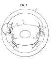
- FIG. 1 shows a vehicle steering wheel which has a hub 3, a Steering wheel rim 5 and four spokes 7.
- a horn keypad, and 11 with multi-function switches are designated.
- Each spoke 7 is in an outer and a radially inner spoke portion 13 and 17 divided to the Decouple the steering wheel rim 5 as far as possible from the hub 3 in terms of vibrations.
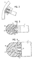
- there is a vibration decoupling device in each spoke 7 provided in the region of the transition of the spoke sections 13, 17, which in FIG 2 is easier to see.
- the inner spoke section 17 has a pin 19 on, which is inserted into a composite bearing 21, which in an opening in the outer Spoke section 13 sits.
- the composite bearing 21 is made of several elastic Composed rings that vibration isolation of the steering wheel rim 5 with attached outer spoke section 13 from the inner Spoke section 17 together with hub 3 reached.
- the vibration decoupling device acts in this as in all other embodiments in all Directions, including radial, axial and circumferential directions.
- the composite bearing 21 forms an elastic compensating element and the outer Spoke section 13 a receiving shell for the pin 19 and the bearing 21st
- FIG. 3 shows the inside of the steering wheel rim, in which a skeleton ring 23 is provided, which is surrounded by a PU foam 25.
- the foaming of which is not explicitly shown is a receiving shell 27 on the skeleton ring 23, z. B. by welding attached, but it can also be cast on.
- the receptacle 27 is also encapsulates, the encapsulation 25 also in the interior 29 of the shell 27 is provided.
- the foam replaces the composite bearing 21 in Figure 2 and forms the elastic compensating element into which the pin 19 of the Spoke 7 protrudes.
- the vibration decoupling is in this embodiment consequently through the receiving shell 27, the PU foam 25 in the area of Interior 29 of the receiving shell 27 and the bearing pin 19 are formed.
- the Decoupling takes place here between the steering wheel rim 5 and the entire one Spoke 7.
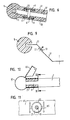
- the bearing shell 27 ' is on the Skeleton ring 23 cast on.
- the elastic compensation element inside the Receiving tray 27 ' is formed by an inserted, elastic bushing 21', into which the pin 19 protrudes.
- each spoke 7 is already in two explained spoke sections 13, 17 divided, including the spoke skeleton consists of two sections 33, 37 which are foamed.
- the foaming is designated 39.
- the skeletal sections 33, 37 are of an elastic Bearing 41, consisting of a metal ring 40 with two inner ring-shaped Bearing sections 43, 45 surrounded by elastic material to a vigorous Connection of the spoke sections 13, 17 with simultaneous vibration decoupling to reach.
- FIGS. 7 and 8 there is the skeleton section of hub 3 and spokes 7 made of sheet metal.
- the steering wheel rim 5 has one Not shown tray, which through an opening 71st is characterized.
- Figure 7 At the start of assembly ( Figure 7) is the upper end 73 of the Spoke 7 obliquely outwards and upwards so that it does not or only slightly in the Opening 71 protrudes.
- Figure 8 By axially shifting the steering wheel rim 5 in Direction of the arrow while holding the hub 3 at the same time will become the spokes 7 pressed down and plastically deformed, with the radially outer upper end 73 is also bent and migrates outward into the opening 71.
- Figure 8 shows the finished state. In this state, for example the sheet metal skeleton of the spokes 7 are foamed.
- this is achieved, for example achieved that the spoke sections 13, 17 each mounting flanges 51, 53rd have overlapping. In the area of the mounting flanges 51, 53 are the spoke sections 13, 17 screwed together. The spoke section 13 is in a receiving shell, not shown here, in the steering wheel rim 5 plugged.
- the steering wheel rim a skeleton ring 81 made of sheet metal with two opposite radial extensions.
- the upper extension 83 of the skeleton ring 81 is before the assembly of the Steering wheel bent upward, as shown in Figure 10. This allows from above the hub including spokes 7, pin 19 and elastic pin placed on the pin 19 Bearings 21 are inserted into the skeleton ring 81. Then the top one Extension 83 bent downward in the direction of the arrow and presses on the bearing 21, see above that this, as shown in Figure 11, gripped and held by the extension 83 becomes. With 85 a slot between extension 83 and skeleton ring 81 is designated.
Landscapes
- Engineering & Computer Science (AREA)
- Chemical & Material Sciences (AREA)
- Combustion & Propulsion (AREA)
- Transportation (AREA)
- Mechanical Engineering (AREA)
- Steering Controls (AREA)
- Steering-Linkage Mechanisms And Four-Wheel Steering (AREA)
Abstract
Description
Claims (12)
- Fahrzeuglenkrad, mit
einer Nabe (3),
wenigstens einer Speiche (7) und
einem Lenkradkranz (5),
dadurch gekennzeichnet, daß an der Speiche (7) eine in alle Richtungen wirkende Schwingungsentkoppelungseinrichtung vorgesehen ist, die den Lenkradkranz (5) von wenigstens einem Abschnitt (17) der Speiche (7) schwingungsmäßig wenigstens weitgehend entkoppelt. - Fahrzeuglenkrad nach Anspruch 1, dadurch gekennzeichnet, daß die Schwingungsentkoppelungseinrichtung am Übergang Speiche (7) zu Lenkradkranz (5) vorgesehen ist.
- Fahrzeuglenkrad nach Anspruch 1, dadurch gekennzeichnet, daß die Schwingungsentkoppelungseinrichtung innerhalb der Speiche (7) vorgesehen ist und Speichenabschnitte (13, 17) schwingungsmäßig voneinander trennt.
- Fahrzeuglenkrad nach einem der vorhergehenden Ansprüche, dadurch gekennzeichnet, daß die Schwingungsentkoppelungseinrichtung durch ein elastisches Lager (21; 21'; 21"; 41) gebildet ist.
- Fahrzeuglenkrad nach Anspruch 4, dadurch gekennzeichnet, daß das Lager (21) ein Verbundlager ist.
- Fahrzeuglenkrad nach Anspruch 4, dadurch gekennzeichnet, daß die Speiche (7) und/oder der Lenkradkranz (5) eine Umschäumung (25) aufweisen/aufweist und daß die Umschäumung (25) Teil des Lagers ist.
- Fahrzeuglenkrad nach einem der Ansprüche 4 bis 6, dadurch gekennzeichnet, daß das Lager (21') einen Zapfen (19) und eine Aufnahmeschale (27; 27') für den Zapfen (19) aufweist, wobei zwischen Aufnahmeschale (27; 27') und Zapfen (19) ein elastisches Ausgleichselement angeordnet ist.
- Fahrzeuglenkrad nach Anspruch 7, dadurch gekennzeichnet, daß der Lenkradkranz (5) einen Skelettring (23) aufweist, wobei am Skelettring der Zapfen (19) oder die Aufnahmeschale (27; 27') befestigt ist und die Speiche (7) die Aufnahmeschale (27; 27') bzw. den Zapfen (19) aufweist.
- Fahrzeuglenkrad nach Anspruch 7 oder 8, dadurch gekennzeichnet, daß die Speiche (7) so flexibel ausgebildet ist, daß bei der Montage der Zapfen in die Aufhahmeschale (27; 27') eindringen kann.
- Fahrzeuglenkrad nach einem der vorhergehenden Ansprüche, dadurch gekennzeichnet, daß die Speiche (7) in Speichenabschnitte (13, 17) geteilt ist und diese Befestigungsflansche (51, 53) aufweisen, welche sich überlappen.
- Fahrzeuglenkrad nach einem der vorhergehenden Ansprüche, dadurch gekennzeichnet, daß die Speiche (7) in Speichenabschnitte (13, 17) geteilt ist, die durch ein die Speichenabschnitte (13, 17) umgebendes Lager (41) als Schwingungsentkoppelungseinrichtung miteinander verbunden sind.
- Fahrzeuglenkrad nach einem der vorhergehenden Ansprüche, gekennzeichnet durch einen Lenkradkranz (5) mit einem Skelettring (81) mit radial einwärts gewandten Fortsätzen (83) aus Blech, die so gebogen sind, daß sie das dem Skelettring (81) zugewandte Ende der Speiche (7) umgreifen.
Applications Claiming Priority (2)
| Application Number | Priority Date | Filing Date | Title |
|---|---|---|---|
| DE20016637U | 2000-09-26 | ||
| DE20016637U DE20016637U1 (de) | 2000-09-26 | 2000-09-26 | Fahrzeuglenkrad |
Publications (2)
| Publication Number | Publication Date |
|---|---|
| EP1190933A2 true EP1190933A2 (de) | 2002-03-27 |
| EP1190933A3 EP1190933A3 (de) | 2006-04-05 |
Family
ID=7946970
Family Applications (1)
| Application Number | Title | Priority Date | Filing Date |
|---|---|---|---|
| EP01122559A Withdrawn EP1190933A3 (de) | 2000-09-26 | 2001-09-25 | Fahrzeuglenkrad |
Country Status (3)
| Country | Link |
|---|---|
| US (1) | US7213486B2 (de) |
| EP (1) | EP1190933A3 (de) |
| DE (1) | DE20016637U1 (de) |
Cited By (1)
| Publication number | Priority date | Publication date | Assignee | Title |
|---|---|---|---|---|
| WO2005123482A3 (de) * | 2004-06-15 | 2006-06-15 | Takata Petri Ag | Schwingungsgedämpftes fahrzeuglenkrad |
Families Citing this family (10)
| Publication number | Priority date | Publication date | Assignee | Title |
|---|---|---|---|---|
| EP1238888B1 (de) * | 2001-03-08 | 2005-04-13 | TRW Automotive Safety Systems GmbH | Schwingungsgedämpftes Fahrzeuglenkrad |
| DE20105434U1 (de) * | 2001-03-28 | 2002-05-16 | TRW Automotive Safety Systems GmbH & Co. KG, 63743 Aschaffenburg | Gassackmodul |
| DE10137995A1 (de) * | 2001-08-02 | 2003-02-13 | Bayerische Motoren Werke Ag | Kraftfahrzeuglenkung mit einem Schwingungstilger |
| US6799488B2 (en) | 2002-06-12 | 2004-10-05 | David R. Snell | Thumb-accessible control housing for steering device |
| DE10247422B3 (de) * | 2002-10-11 | 2004-07-15 | Daimlerchrysler Ag | Lenkrad für ein Kraftfahrzeug |
| US8505701B2 (en) * | 2010-08-18 | 2013-08-13 | Autoliv Asp, Inc. | Mass-damper system |
| US9308930B2 (en) * | 2012-04-06 | 2016-04-12 | Autoliv Asp, Inc. | Steering wheel with switch assembly |
| US9096257B1 (en) * | 2014-06-30 | 2015-08-04 | Ford Global Technologies, Llc | Extensible steering wheel for passive restraint support |
| US9415791B1 (en) | 2015-02-04 | 2016-08-16 | Ford Global Technologies, Llc | Steering wheel assembly for a vehicle |
| DE102017218038B4 (de) * | 2017-09-28 | 2020-01-30 | Joyson Safety Systems Germany Gmbh | Lenkrad für ein Kraftfahrzeug |
Citations (1)
| Publication number | Priority date | Publication date | Assignee | Title |
|---|---|---|---|---|
| DE2013795B2 (de) | 1970-03-23 | 1978-11-16 | Peter 8175 Reichersbeuern Angerer | Sicherheitslenkrad |
Family Cites Families (19)
| Publication number | Priority date | Publication date | Assignee | Title |
|---|---|---|---|---|
| GB440320A (en) * | 1935-09-14 | 1935-12-24 | Frank Ashby And Sons Ltd | Improvements in hand steering wheels |
| FR850310A (fr) * | 1938-02-17 | 1939-12-14 | Volant antivibrant | |
| DE1209894B (de) * | 1964-01-30 | 1966-01-27 | Fendt & Co Xaver | Lenkrad mit Daempfungseinrichtung fuer Schlepper |
| JPS5699858A (en) * | 1980-01-16 | 1981-08-11 | Toyota Motor Corp | Steering wheel |
| JPS5758556A (en) * | 1980-09-26 | 1982-04-08 | Nissan Motor Co Ltd | Steering wheel |
| JPS6237273A (ja) * | 1985-08-09 | 1987-02-18 | Nissan Shatai Co Ltd | ステアリング装置 |
| US4821598A (en) * | 1986-11-05 | 1989-04-18 | Toyota Jidosha Kabushiki Kaisha | Steering wheel core material |
| JPH01229763A (ja) * | 1988-03-11 | 1989-09-13 | Toyota Autom Loom Works Ltd | 防振型ステアリングホイール |
| JPH0545588Y2 (de) * | 1988-08-08 | 1993-11-22 | ||
| US5508482A (en) * | 1994-10-11 | 1996-04-16 | General Motors Corporation | Horn activation and steering wheel assembly |
| JP3169206B2 (ja) | 1996-02-28 | 2001-05-21 | 日本プラスト株式会社 | ステアリングホイール |
| IT1284671B1 (it) * | 1996-07-16 | 1998-05-21 | Bruzolo Manifatt Gestind Mb | Volante di sterzo per autoveicoli. |
| DE69725246T2 (de) * | 1996-08-06 | 2004-07-29 | Toyoda Gosei Co., Ltd., Haruhi | Lenkrad |
| DE19731314A1 (de) * | 1997-07-16 | 1999-01-28 | Petri Ag | Lenkrad mit Airbagmodul |
| DE69906924T2 (de) * | 1999-02-19 | 2004-01-29 | Breed Automotive Tech | Herstellungsverfahren für ein Kraftfahrzeuglenkrad mit einer äusseren Hülle aus Verbundmaterial |
| DE19908916C2 (de) | 1999-03-02 | 2001-06-21 | Freudenberg Carl Fa | Schwingungstilger für Lenkräder von Kraftfahrzeugen |
| DE29910992U1 (de) * | 1999-06-23 | 1999-11-04 | TRW Automotive Safety Systems GmbH & Co.KG, 63743 Aschaffenburg | Fahrzeuglenkrad |
| DE29910991U1 (de) * | 1999-06-23 | 1999-11-04 | TRW Automotive Safety Systems GmbH & Co.KG, 63743 Aschaffenburg | Fahrzeuglenkrad |
| JP3386015B2 (ja) * | 1999-09-06 | 2003-03-10 | ヤマハ株式会社 | ステアリングホイールの製法 |
-
2000
- 2000-09-26 DE DE20016637U patent/DE20016637U1/de not_active Expired - Lifetime
-
2001
- 2001-09-25 EP EP01122559A patent/EP1190933A3/de not_active Withdrawn
- 2001-09-26 US US09/963,909 patent/US7213486B2/en not_active Expired - Fee Related
Patent Citations (1)
| Publication number | Priority date | Publication date | Assignee | Title |
|---|---|---|---|---|
| DE2013795B2 (de) | 1970-03-23 | 1978-11-16 | Peter 8175 Reichersbeuern Angerer | Sicherheitslenkrad |
Cited By (1)
| Publication number | Priority date | Publication date | Assignee | Title |
|---|---|---|---|---|
| WO2005123482A3 (de) * | 2004-06-15 | 2006-06-15 | Takata Petri Ag | Schwingungsgedämpftes fahrzeuglenkrad |
Also Published As
| Publication number | Publication date |
|---|---|
| US7213486B2 (en) | 2007-05-08 |
| US20020035889A1 (en) | 2002-03-28 |
| DE20016637U1 (de) | 2001-02-08 |
| EP1190933A3 (de) | 2006-04-05 |
Similar Documents
| Publication | Publication Date | Title |
|---|---|---|
| DE60124631T2 (de) | Vorrichtung zur Dämpfung von Drehmomentschwankungen mit einer Struktur zur Verringerung von Ausrichtungsfehlern des Drehmomentbegrenzers beim Zusammenbau | |
| EP1320691B1 (de) | Maschinengehäuse | |
| DE4340607B4 (de) | Lager zur drehbaren Lagerung einer Welle | |
| DE112017005369B4 (de) | Fahrzeugrahmen-stützapparat | |
| DE69937208T2 (de) | Schwungrad für Verbrennungsmotor | |
| EP1108156B1 (de) | Federbeinlager | |
| EP2147232A1 (de) | Differential in leichtbauweise für kraftfahrzeuge | |
| EP0560058A2 (de) | Zentriertes Doppelgelenk für Lenkwellen in Kraftfahrzeugen | |
| EP0472828B1 (de) | Lagerung für einen Gangschalthebel | |
| WO2019105810A1 (de) | Spindelantriebsbaugruppe sowie fahrzeugklappe mit einer spindelantriebsbaugruppe | |
| DE10326037B4 (de) | Mittellager-Resonanzdämpfer | |
| DE20016637U1 (de) | Fahrzeuglenkrad | |
| DE3420570C1 (de) | Drehschwingungstilger | |
| DE102004013489B4 (de) | Radnabe und Verfahren zum Montieren eines Rads | |
| DE102018205473A1 (de) | Lagerung für ein Hybridmodul | |
| DE3808025A1 (de) | Schalthebel | |
| AU4483499A (en) | Arrangement for mounting a pinion gear within a housing of a differential assembly | |
| DE10059684B4 (de) | Differenzialgetriebe für Kraftfahrzeuge | |
| EP1238888A2 (de) | Schwingungsgedämpftes Fahrzeuglenkrad | |
| DE60004277T2 (de) | Schwingungsdämpfendes Lager und Verfahren zur Herstellung | |
| DE69705341T2 (de) | Hydraulisches, schwingungsdämpfendes Lager und Kraftfahrzeug-Unterbaugruppe mit einem solchen Lager | |
| EP1177391B1 (de) | Zweivorgelegewellengetriebe | |
| DE102010048341A1 (de) | Vorderachsträger eines Fahrzeugs mit Lenkgetriebe | |
| DE19904850A1 (de) | Torsionsschwingungsdämpfer | |
| DE2442351C2 (de) | In der Befestigung des Hinterachsgetriebes gegenüber dem Fahrzeugoberbau vorgesehenes elastisches Befestigungselement |
Legal Events
| Date | Code | Title | Description |
|---|---|---|---|
| PUAI | Public reference made under article 153(3) epc to a published international application that has entered the european phase |
Free format text: ORIGINAL CODE: 0009012 |
|
| AK | Designated contracting states |
Kind code of ref document: A2 Designated state(s): AT BE CH CY DE DK ES FI FR GB GR IE IT LI LU MC NL PT SE TR |
|
| AX | Request for extension of the european patent |
Free format text: AL;LT;LV;MK;RO;SI |
|
| PUAL | Search report despatched |
Free format text: ORIGINAL CODE: 0009013 |
|
| AK | Designated contracting states |
Kind code of ref document: A3 Designated state(s): AT BE CH CY DE DK ES FI FR GB GR IE IT LI LU MC NL PT SE TR |
|
| AX | Request for extension of the european patent |
Extension state: AL LT LV MK RO SI |
|
| 17P | Request for examination filed |
Effective date: 20060926 |
|
| AKX | Designation fees paid |
Designated state(s): DE ES FR GB IT |
|
| 17Q | First examination report despatched |
Effective date: 20061115 |
|
| STAA | Information on the status of an ep patent application or granted ep patent |
Free format text: STATUS: THE APPLICATION IS DEEMED TO BE WITHDRAWN |
|
| 18D | Application deemed to be withdrawn |
Effective date: 20070327 |