EP1190773B1 - Stiftmühle - Google Patents
Stiftmühle Download PDFInfo
- Publication number
- EP1190773B1 EP1190773B1 EP20010118338 EP01118338A EP1190773B1 EP 1190773 B1 EP1190773 B1 EP 1190773B1 EP 20010118338 EP20010118338 EP 20010118338 EP 01118338 A EP01118338 A EP 01118338A EP 1190773 B1 EP1190773 B1 EP 1190773B1
- Authority
- EP
- European Patent Office
- Prior art keywords
- pin
- mill
- pin mill
- medium
- insulating
- Prior art date
- Legal status (The legal status is an assumption and is not a legal conclusion. Google has not performed a legal analysis and makes no representation as to the accuracy of the status listed.)
- Expired - Lifetime
Links
Images


Classifications
-
- B—PERFORMING OPERATIONS; TRANSPORTING
- B02—CRUSHING, PULVERISING, OR DISINTEGRATING; PREPARATORY TREATMENT OF GRAIN FOR MILLING
- B02C—CRUSHING, PULVERISING, OR DISINTEGRATING IN GENERAL; MILLING GRAIN
- B02C19/00—Other disintegrating devices or methods
- B02C19/18—Use of auxiliary physical effects, e.g. ultrasonic waves or irradiation, for disintegrating
- B02C19/186—Use of cold or heat for disintegrating
-
- B—PERFORMING OPERATIONS; TRANSPORTING
- B02—CRUSHING, PULVERISING, OR DISINTEGRATING; PREPARATORY TREATMENT OF GRAIN FOR MILLING
- B02C—CRUSHING, PULVERISING, OR DISINTEGRATING IN GENERAL; MILLING GRAIN
- B02C13/00—Disintegrating by mills having rotary beater elements ; Hammer mills
- B02C13/22—Disintegrating by mills having rotary beater elements ; Hammer mills with intermeshing pins ; Pin Disk Mills
Definitions
- the invention relates to a pin mill, in particular a pin mill with opposing pin discs.
- Such mills are preferred for grinding oily or fatty foods, e.g. Cocoa, coffee and spices used. These mills can also be used for grinding plastics.
- the grinding takes place with the addition of liquid nitrogen for cooling the material during the grinding.
- the cooling embrittles elastic millbase such. Plastic, whereby this is only grindable.
- it is advantageous for spices that no heating occurs and therefore the heat-sensitive essential oils contained in the spices are largely retained.
- the pin mill When operating the pin mill with a refrigerant, not only is the regrind cooled to low temperatures, but the mill also cools down. In particular, the housing, the drive shafts and the bearings are cooled to a very low temperature.
- the rolling bearings required for the rotatable mounting of the pin disks are usually designed for very high temperatures and generally just not for operation at very low temperatures.
- Bearings that are particularly suitable for low temperatures are special bearings that are more expensive than standard bearings. Such special bearings, in turn, can not be operated at high temperatures.
- the object of the invention is therefore to structurally design a pin mill such that standard bearings can be used for operation at both high and low temperatures.
- the object of the invention is achieved in that the bearings on the pin mill are structurally designed so that a heat transfer from the housing of the pin mill is largely prevented on the bearings, in particular by thermal insulation of the bearing cups relative to the pin mill housing.
- a thermal insulation is achieved in that grease-lubricated standard bearings are pre-assembled in a storage pot.
- the storage pots are arranged in the mill so that between them and the mill housing, a gap is formed, which is traversed by a preferably gaseous insulating medium. Through this gas-filled gap effective thermal insulation of storage pots and mill housing is achieved.
- the insulating medium also serves as flushing medium for the rinsing gap between the mill housing and the drive shaft of the inlet side pin disc so serve between the grinding chamber and the bearing pots.
- the pin mill according to the invention has a distribution space, which distributes a supplied flushing medium for the flushing column between the inlet region of the mill and the fine material space via a plurality of passages.
- the gaseous medium which flows through a common intermediate space can simultaneously serve as an insulating medium and as a flushing medium for the rinsing gaps between the inlet region of the mill and the fine material space, as well as between the grinding chamber and the storage pots.
- the gaseous medium can be tempered.
- a flushing medium with ambient temperature is the simplest and least expensive.
- the preheating of the flushing medium does not significantly affect the millbase temperature in many cases, since the millbase lingers only a very short time in the grinding chamber and the rinsing gaps are preferably designed so that only a very small volume flow of flushing medium flows.
- the purging air quantity is adjusted.
- an adapted plurality of flushing medium passages are provided between the intermediate space and the gap seals. Depending on the number and distribution of the flushing medium passages, the distribution and the amount of purging air can be adjusted.
- a cooled scavenging air as a cooling medium, namely when high speeds and high energies are required for grinding the material, so much energy must be introduced into the millbase to achieve a digestion of the ground material.
- the material to be ground is heated very quickly and possibly loses its brittle properties and is then no longer grindable.
- it is then advantageous to cool the flushing medium so that the energy introduced into the mill can be dissipated quickly.
- pin mills can be run in conventional storage technology, especially with grease lubrication and operate without additional equipment for temperature control of the camp. In the event of a fault, if e.g. Too much liquid coolant entering the mill will then prevent bearing damage.
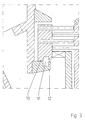
- the special construction of the flushing column according to FIG. 3 additionally makes it possible to design these on the smallest inner diameter with a long, narrow gap to the outside and with a short, wide gap inwards.
- Fig. 1 shows an opposed pin mill with two pin disks 14a and 14b driven by shafts 23a and 23b supported in the bearing cups 1a and 1b .
- the bearing pans 1a and 1b are insulating bushes 2a and 2b connected via temperature with the mill housing. 3
- the insulation chambers 4a and 4b provided in the mill housing 3 surround the bearing pots 1a and 1b and prevent heat transfer between the bearing pots 1a and 1b to the inlet shaft of the grinding material inlet 5 and the Mahlgutauslrawraum 16.
- the connection openings 7a, 7b allow the supply of an insulating medium in the isolation 4a , 4b and at the same time allow the flushing of the Spülspalte 6a and 6b.
- the separate from the insulating space 4a manifold 8 directs the introduced via the feed 9 flushing medium to a plurality of evenly distributed on a radius flushing medium passages 10 in the space 11 of the outer peripheral outer gap seal 13 and lying on the inner circumference inner gap seal 12 is limited.
- the flushed gap seal 12 , 13 which acts in this way outwards and inwards, separates the space of the grinding material inlet 5 from the fine-material outlet space 16. The details given are shown in FIG. 3 .
- the annular channel 19a distributes a cooling medium supplied through the opening 18a to a plurality of cooling medium passages 20a uniformly distributed over the circumference of the pin disk 14a disposed on the inlet side for cooling the back side of the pin disk 14a. After flowing through the gap channel 21a , the cooling medium enters the fine-material outlet space 16 via the outer gap seal 17a .
- the annular channel 19b distributes a cooling medium supplied via the opening 18b to a plurality of cooling medium passages 20b, which are distributed uniformly over the circumference of the pin disk 14b opposite the inlet, for cooling the rear side of the pin disk 14b. After flowing through the gap channel 21b , the cooling medium enters the fine material space 16 via the outer gap seal 17b .
- these are preferably surrounded by an insulating sheath 24a and 24b .
- FIG. 2 The sectional view of Fig. 2 shows the insulating space 4a as it surrounds the bearing cup 1a .
- the insulating medium is supplied via the connection opening 7a .
- the rinsing medium for supplying the rinsing gap between the inlet region of the mill and the fine material space passes into the distribution space 8, which has a multiplicity of rinsing medium passages 10 .
- the supply of the gap channel 21a for cooling the rear side of the inlet-side pin disk 14a takes place via the opening 18a in the annular channel 19a via the cooling medium passages 20a.
Landscapes
- Engineering & Computer Science (AREA)
- Food Science & Technology (AREA)
- Health & Medical Sciences (AREA)
- Toxicology (AREA)
- Crushing And Grinding (AREA)
Description
- Die Erfindung betrifft eine Stiftmühle, insbesondere eine Stiftmühle mit gegenläufigen Stiftscheiben. Solche Mühlen werden bevorzugt zur Mahlung von öl- oder fetthaltigen Nahrungsmitteln, wie z.B. Kakao, Kaffee und Gewürzen eingesetzt. Auch zur Mahlung von Kunststoffen sind diese Mühlen einsetzbar.
- Oft erfolgt dabei die Mahlung unter Zugabe von flüssigem Stickstoff zur Kühlung des Gutes während der Mahlung. Das Kühlen versprödet elastisches Mahlgut wie z.B. Kunststoff, wodurch dieses erst mahlbar wird. Bei der Mahlung von z.B. Gewürzen ist es von Vorteil, das keine Erhitzung auftritt und daher die in den Gewürzen enthaltenen, wärmeempfindlichen ätherischen Öle weitgehend erhalten bleiben.
- Aus der
deutschen Offenlegungsschrift DE-OS 27 13 809 A1 ist beispielsweise eine Stiftmühle zum Kaltmahlen von Gummigranulat bekannt, die zwei gegenüberliegende Stiftscheiben aufweist. - Zähe, elastische Stoffe wie z.B. Gummi lassen sich auch bei hohen Drehzahlen der Stiftscheiben bei Normaltemperatur nicht oder nur unzureichend zu feinem Pulver zerkleinern. Die Mahlung mit flüssigem Stickstoff oder einem anderen Kältemittel versprödet das Mahlgut vor der Mahlung. In diesem tief gekühlten Zustand lassen sich diese Stoffe sodann vermahlen.
- Im Betrieb der Stiftmühle mit einem Kältemittel wird nicht nur das Mahlgut auf tiefe Temperaturen abgekühlt, sondern auch die Mühle kühlt sich ab. Es wird dabei insbesondere das Gehäuse, die Antriebswellen und die Lagerungen auf eine sehr tiefe Temperatur abgekühlt.
- Die für die drehbare Lagerung der Stiftscheiben erforderlichen Wälzlager sind jedoch üblicherweise für sehr hohe Temperaturen und im allgemeinen gerade nicht für den Betrieb bei sehr tiefen Temperaturen ausgelegt.
- Lagerungen, die für tiefe Temperaturen besonders geeignet sind, stellen Speziallager dar, die teurer als Standardlagerungen sind. Solche Speziallager können wiederum nicht bei hohen Temperaturen betrieben werden.
- Aufgabe der Erfindung ist es deshalb eine Stiftmühle konstruktiv derart auszugestalten, daß Standardlagerungen für einen Betrieb bei sowohl hohen als auch bei niedrigen Temperaturen eingesetzt werden können.
- Die erfindungsgemäße Aufgabe wird dadurch gelöst, daß die Lagerungen an der Stiftmühle konstruktiv derart ausgebildet sind, daß ein Wärmeübergang vom Gehäuse der Stiftmühle auf die Lagerungen weitgehend verhindert wird, insbesondere durch eine thermische Isolierung der Lagertöpfe gegenüber dem Stiftmühlengehäuse.
- In einer bevorzugten Ausgestaltung wird eine thermische Isolierung dadurch erreicht, daß fettgeschmierte Standardlager in einem Lagertopf vormontiert sind. Die Lagertöpfe sind in der Mühle derart angeordnet, daß zwischen ihnen und dem Mühlengehäuse ein Zwischenraum gebildet wird, der von einem vorzugsweise gasförmigen Isoliermedium durchströmt wird. Durch diesen gasgefüllten Zwischenraum wird eine wirkungsvolle thermische Isolierung von Lagertöpfen und Mühlengehäuse erreicht. Das Isoliermedium dient gleichzeitig als Spülmedium für den Spülspalt zwischen Mühlengehäuse und Antriebswelle der einlaufseitigen Stiftscheibe also zwischen Mahlraum und den Lagertöpfen dienen.
- Neben dem Isolierraum, der durch das Isoliermedium durchströmt wird, verfügt die erfindungsgemäße Stiftmühle über einen Verteilerraum, der ein zugeführtes Spülmedium für die Spülspalte zwischen Einlaufbereich der Mühle und dem Feingutraum über eine Vielzahl von Durchtritten verteilt.
- In einer besonders vorteilhaften Ausgestaltung kann das gasförmige Medium, das einen gemeinsamen Zwischenraum durchströmt gleichzeitig als Isoliermedium und als Spülmedium für die Spülspalte zwischen Einlaufbereich der Mühle und dem Feingutraum, sowie zwischen Mahlraum und den Lagertöpfen dienen. Das gasförmige Medium kann temperiert sein. Im allgemeinen ist ein Spülmedium mit Umgebungstemperatur am einfachsten und kostengünstigsten. In besonderen Fällen, wenn z.B. das Mahlgut auf extrem tiefe Temperatur gekühlt ist, kann es von Vorteil sein das Spülmedium vorzuwärmen, damit die Lagertöpfe nicht unterkühlen. Die Vorwärmung des Spülmediums wirkt sich dabei auf die Mahlguttemperatur in vielen Fällen nicht wesentlich aus, da das Mahlgut nur sehr kurze Zeit im Mahlraum verweilt und die Spülspalte vorzugsweise so gestaltet sind, daß nur ein sehr geringer Volumenstrom an Spülmedium fließt.
- In Abhängigkeit von den jeweiligen Spaltgeometrien zwischen Einlaufbereich der Mühle und dem Feingutraum, sowie zwischen Mahlraum und den Lagertöpfen wird die Spülluftmenge eingestellt. Dazu werden eine angepaßte Vielzahl von Spülmedium-Durchtritte zwischen dem Zwischenraum und den Spaltdichtungen vorgesehen. Je nach Anzahl und Verteilung der Spülmedium-Durchtritte kann die Verteilung und die Menge der Spülluft eingestellt werden.
- Neben der verbesserten Wärmeisolierung der Lagertöpfe durch angewärmte Spülluft als Isoliermedium kann es jedoch auch sinnvoll sein, eine gekühlte Spülluft als Kühlmedium einzusetzen, nämlich dann wenn zur Mahlung des Gutes hohe Drehzahlen und hohe Energien erforderlich sind, also viel Energie in das Mahlgut eingebracht werden muß um einen Aufschluß des Mahlgutes zu erreichen. Durch einen hohen Energieeintrag während der Mahlung wird das Mahlgut nämlich sehr schnell erwärmt und verliert evtl. seine spröden Eigenschaften und ist dann nicht mehr mahlbar. Um den hohen Energieeintrag kompensieren zu können ist es dann vorteilhaft das Spülmedium zu kühlen, damit die in die Mühle eingetragene Energie schnell abgeführt werden kann. Bei einer derartigen Kühlen des Spülmediums kann es auch von Vorteil sein die Spülluftmenge zu erhöhen, z.B. durch Erhöhen der Anzahl oder des Durchmessers der Durchtritte zwischen dem Zwischenraum und den Spaltdichtungen.
- Um auch einen Wärmeübergang an den Antriebswellen der Stiftscheiben zu verhindern können diese mit einem einer isolierenden Hülle versehen sein.
- Durch die genannten Maßnahmen lassen sich Stiftmühlen in konventioneller Lagertechnik, insbesondere mit Fettschmierung ausführen und ohne Zusatzeinrichtungen für eine Temperierung der Lager betreiben. Im Störfall, wenn z.B. zu viel flüssiges Kühlmittel in die Mühle eintritt werden dann Lagerschäden verhindert.
- Durch die Gestaltung der Spülmedium durchströmten Räume und Durchtritte kann der Spülluftverbrauch optimal eingestellt werden, dies insbesondere bei Mahlvorgängen, die ohne zusätzliches Kühlmedium betrieben werden. Die besondere Konstruktion der Spülspalte nach Figur 3 erlauben es zusätzlich, diese auf dem kleinsten Innendurchmesser mit langem, engen Spalt nach außen und mit kurzem, weiten Spalt nach innen zu gestalten.
-
- Fig.1
- zeigt einen Querschnitt durch eine erfindungsgemäße Stiftmühle.
- Fig.2
- zeigt einen Längsschnitt durch eine erfindungsgemäße Stiftmühle.
- Fig.3
- zeigt eine vergrößerte Ansicht des erfindungsgemäßen Spülspaltes.
- Fig.1 zeigt eine gegenläufige Stiftmühle mit zwei Stiftscheiben 14a und 14b, die über Wellen 23a und 23b, die in den Lagertöpfen 1a und 1b gelagert sind angetrieben werden. Die Lagertöpfe 1a und 1b sind über Temperatur isolierende Buchsen 2a und 2b mit dem Mühlengehäuse 3 verbunden.
- Die im Mühlengehäuse 3 vorgesehenen Isolierräume 4a und 4b umgeben die Lagertöpfe 1a und 1b und verhindern einen Wärmeübergang zwischen den Lagertöpfen 1a und 1b hin zum Einlaufschacht des Mahlguteinlaßes 5 und dem Mahlgutauslaßraum 16. Die Anschlußöffnungen 7a, 7b ermöglichen die Zuführung eines Isoliermediums in die Isolierräume 4a, 4b und ermöglichen gleichzeitig die Spülung der Spülspalte 6a und 6b.
- Der vom Isolierraum 4a getrennte Verteilerraum 8 leitet das über die Zuführung 9 eingeleitete Spülmedium zu einer Vielzahl von gleichmäßig auf einem Radius verteilten Spülmedium-Durchtritte 10 in den Zwischenraum 11 der von einer am äußeren Umfang liegenden äußeren Spaltdichtung 13 und einer am inneren Umfang liegenden inneren Spaltdichtung 12 begrenzt wird. Die so nach außen und innen wirkende, gespülte Spaltdichtung 12,13 trennt den Raum des Mahlguteinlaßes 5 von dem Feingutauslaßraum 16. Die genannten Einzelheiten sind in Fig. 3 herausgestellt.
- Der Ringkanal 19a verteilt ein über die Öffnung 18a zugeführtes Kühlmedium auf eine Vielzahl von Kühlmedium-Durchtritte 20a, die gleichmäßig über den Umfang der auf der Einlaufseite angeordneten Stiftscheibe 14a verteilt sind, zur Kühlung der Rückseite der Stiftscheibe 14a. Das Kühlmedium tritt nach Durchströmen des Spaltkanals 21a über die äußere Spaltdichtung 17a in den Feingutauslaßraum 16 ein.
- Der Ringkanal 19b verteilt ein über die Öffnung 18b zugeführtes Kühlmedium auf eine Vielzahl von Kühlmedium-Durchtritte 20b, die gleichmäßig über den Umfang der dem Einlauf gegenüberliegenden Stiftscheibe 14b verteilt sind, zur Kühlung der Rückseite der Stiftscheibe 14b. Das Kühlmedium tritt nach Durchströmen des Spaltkanals 21b über die äußere Spaltdichtung 17b in den Feingutraum 16 ein.
- Zur Kälteisolierung der Wellen 23a und 23b sind diese vorzugsweise mit einer isolierenden Hülle 24a und 24b umgeben.
- Die Schnittdarstellung von Fig. 2 zeigt den Isolierraum 4a wie er den Lagertopf 1a umgibt. Das Isoliermedium wird über die Anschlußöffnung 7a zugeführt.
- Über die Zuführung 9 gelangt das Spülmedium zur Versorgung des Spülspaltes zwischen Einlaufbereich der Mühle und dem Feingutraum in den Verteilraum 8, der eine Vielzahl von Spülmedium-Durchtritten 10 aufweist.
- Die Versorgung des Spaltkanals 21a zur Kühlung der Rückseite der einlaufseitigen Stiftscheibe 14a erfolgt über die Öffnung 18a in den Ringkanal 19a über die Kühlmedium-Durchtritte 20a.
Claims (8)
- Stiftmühle zum Kaltmahlen von Mahlgut mit zwei gegenüberliegend angeordneten, zusammenwirkenden Stiftscheiben (14a,14b) zum Mahlen des Gutes, wobei mindestens eine der beiden Stiftscheiben (14a,14b) über eine in Wälzagern drehbare Welle (23a,23b) angetrieben ist, mit einem Mühlengehäuse (3) zur Aufnahme der beiden Stiftscheiben (14a,14b), sowie einem Mahlguteinlaß (5) und einem Feingutauslaßraum (16), sowie Mitteln zum Spülen von Spaltdichtungen (11,12,13,21a,21b) zwischen dem Mahlguteinlaß (5) und dem Feingutauslaßraum (16) der Stiftmühle dadurch gekennzeichnet, daß die Wälzlager jeder drehbaren Welle (23a,23b) in einem separaten Lagertopf (1a,1b) gehalten sind, wobei sich zwischen jedem Lagertopf (1a,1b) und dem Mühlengehäuse (3) ein Isolierraum (4a,4b) befindet, der die Lagertöpfe (1a,1b) thermisch von dem Mühlengehäuse (3) trennt.
- Stiftmühle nach Anspruch 1, dadurch gekennzeichnet, daß die Isolierräume (4a,4b) mit einem gasförmigen Medium spülbar sind.
- Stiftmühle nach Anspruch 2, dadurch gekennzeichnet, daß das gasförmige Medium vorgewärmt ist.
- Stiftmühle nach Anspruch 1, dadurch gekennzeichnet, daß die Lagertöpfe (1a,1b) über Temperatur isolierende Buchsen 2a und 2b mit dem Mühlengehäuse 3 verbunden sind.
- Stiftmühle nach Anspruch 1 bis 4, gekennzeichnet durch mindestens einen weiteren vom Isolierraum (4a,4b) getrennten Gehäuseraum (19a,19b) zum Verteilen eines Spülmediums an die Spaltdichtungen (11,12,13,21a,21b).
- Stiftmühle nach Anspruch 5, dadurch gekennzeichnet, daß das Spülmedium gekühlt ist.
- Stiftmühle nach Anspruch 5 oder 6, dadurch gekennzeichnet, daß das Spülmedium über Durchtritte (10, 20a,20b) in gleichmäßiger Verteilung in die Spaltdichtungen (11,12,13,21a,21b) einführbar ist.
- Stiftmühle nach Anspruch 1 bis 7, dadurch gekennzeichnet, daß mindestens eine der beiden Wellen (23a,23b) eine thermisch isolierende Hülle aufweist.
Applications Claiming Priority (2)
| Application Number | Priority Date | Filing Date | Title |
|---|---|---|---|
| DE2000146769 DE10046769A1 (de) | 2000-09-21 | 2000-09-21 | Stiftmühle |
| DE10046769 | 2000-09-21 |
Publications (2)
| Publication Number | Publication Date |
|---|---|
| EP1190773A1 EP1190773A1 (de) | 2002-03-27 |
| EP1190773B1 true EP1190773B1 (de) | 2007-11-28 |
Family
ID=7657087
Family Applications (1)
| Application Number | Title | Priority Date | Filing Date |
|---|---|---|---|
| EP20010118338 Expired - Lifetime EP1190773B1 (de) | 2000-09-21 | 2001-07-27 | Stiftmühle |
Country Status (3)
| Country | Link |
|---|---|
| EP (1) | EP1190773B1 (de) |
| DE (2) | DE10046769A1 (de) |
| ES (1) | ES2295090T4 (de) |
Families Citing this family (18)
| Publication number | Priority date | Publication date | Assignee | Title |
|---|---|---|---|---|
| DE20208606U1 (de) * | 2002-06-03 | 2003-10-16 | Pallmann Maschinenfabrik GmbH & Co KG, 66482 Zweibrücken | Zerkleinerungsvorrichtung |
| RU2290997C1 (ru) * | 2005-05-17 | 2007-01-10 | Республиканское унитарное предприятие Специальное конструкторско-технологическое бюро "Металлополимер" | Дисмембратор |
| CA2680185A1 (en) * | 2007-03-06 | 2008-09-12 | Archer-Daniels-Midland Company | Method and apparatus for producing cocoa products |
| DE102009040925A1 (de) * | 2009-09-11 | 2011-03-31 | Teutoburger Ölmühle GmbH & Co. KG | Nutzung von geschälten Rapssamen |
| RU2535165C1 (ru) * | 2013-05-08 | 2014-12-10 | Федеральное государственное бюджетное образовательное учреждение высшего профессионального образования "Алтайский государственный технический университет им. И.И. Ползунова" (АлтГТУ) | Роторно-пульсационный аппарат |
| RU2630936C1 (ru) * | 2016-05-31 | 2017-09-14 | федеральное государственное бюджетное образовательное учреждение высшего образования "Белгородский государственный технологический университет им. В.Г. Шухова" | Дезинтегратор |
| RU2633554C1 (ru) * | 2016-12-07 | 2017-10-13 | федеральное государственное бюджетное образовательное учреждение высшего образования "Белгородский государственный технологический университет им. В.Г. Шухова" | Дезинтегратор |
| RU2725318C1 (ru) * | 2019-05-22 | 2020-07-02 | федеральное государственное бюджетное образовательное учреждение высшего образования "Белгородский государственный технологический университет им. В.Г. Шухова" | Дезинтегратор |
| RU2725316C1 (ru) * | 2019-05-22 | 2020-07-02 | федеральное государственное бюджетное образовательное учреждение высшего образования "Белгородский государственный технологический университет им. В.Г. Шухова" | Дезинтегратор |
| RU2714768C1 (ru) * | 2019-06-13 | 2020-02-19 | федеральное государственное бюджетное образовательное учреждение высшего образования "Белгородский государственный технологический университет им. В.Г. Шухова" | Дезинтегратор |
| RU2714778C1 (ru) * | 2019-07-03 | 2020-02-19 | федеральное государственное бюджетное образовательное учреждение высшего образования "Белгородский государственный технологический университет им. В.Г. Шухова" | Дезинтегратор |
| RU2724668C1 (ru) * | 2019-11-19 | 2020-06-25 | федеральное государственное бюджетное образовательное учреждение высшего образования "Белгородский государственный технологический университет им. В.Г. Шухова" | Дезинтегратор |
| RU2724671C1 (ru) * | 2019-12-09 | 2020-06-25 | федеральное государственное бюджетное образовательное учреждение высшего образования "Белгородский государственный технологический университет им. В.Г. Шухова" | Дезинтегратор |
| RU2728226C1 (ru) * | 2020-02-17 | 2020-07-28 | федеральное государственное бюджетное образовательное учреждение высшего образования "Белгородский государственный технологический университет им. В.Г. Шухова" | Дезинтегратор |
| RU2733663C1 (ru) * | 2020-03-25 | 2020-10-06 | федеральное государственное бюджетное образовательное учреждение высшего образования "Белгородский государственный технологический университет им. В.Г. Шухова" | Дезинтегратор |
| RU2739425C1 (ru) * | 2020-10-08 | 2020-12-24 | федеральное государственное бюджетное образовательное учреждение высшего образования «Белгородский государственный технологический университет им. В.Г. Шухова» | Дезинтегратор |
| RU2745609C1 (ru) * | 2020-10-20 | 2021-03-29 | федеральное государственное бюджетное образовательное учреждение высшего образования «Белгородский государственный технологический университет им. В.Г. Шухова» | Дезинтегратор |
| RU2748680C1 (ru) * | 2020-11-10 | 2021-05-28 | федеральное государственное бюджетное образовательное учреждение высшего образования «Белгородский государственный технологический университет им. В.Г. Шухова» | Дезинтегратор |
Family Cites Families (4)
| Publication number | Priority date | Publication date | Assignee | Title |
|---|---|---|---|---|
| DE2713809C2 (de) | 1977-03-29 | 1982-06-09 | Messer Griesheim Gmbh, 6000 Frankfurt | Stiftmühle zum Kaltmahlen von Gummigranulat |
| US4718609A (en) * | 1986-03-20 | 1988-01-12 | T. D. J. Co., Inc. | Material comminutor |
| DE4125572A1 (de) * | 1990-08-16 | 1992-02-20 | Eberlein Sonja | Turbomuehle mit neuartig ausgebildeten radialen kuehlkammern |
| DE4025969A1 (de) * | 1990-08-16 | 1992-02-20 | Eberlein Sonja | Turbomuehle mit neuartiger lagereinrichtung |
-
2000
- 2000-09-21 DE DE2000146769 patent/DE10046769A1/de not_active Withdrawn
-
2001
- 2001-07-27 ES ES01118338T patent/ES2295090T4/es not_active Expired - Lifetime
- 2001-07-27 EP EP20010118338 patent/EP1190773B1/de not_active Expired - Lifetime
- 2001-07-27 DE DE50113315T patent/DE50113315D1/de not_active Expired - Lifetime
Also Published As
| Publication number | Publication date |
|---|---|
| DE50113315D1 (de) | 2008-01-10 |
| ES2295090T4 (es) | 2008-06-16 |
| EP1190773A1 (de) | 2002-03-27 |
| ES2295090T3 (es) | 2008-04-16 |
| DE10046769A1 (de) | 2002-04-11 |
Similar Documents
| Publication | Publication Date | Title |
|---|---|---|
| EP1190773A1 (de) | Stiftmühle | |
| EP0340503B1 (de) | Beheizbare Walze | |
| DE3025876C2 (de) | Keilflächen-Axialgleitlager | |
| DE3443537C2 (de) | ||
| DE3014891C2 (de) | ||
| DE4401384A1 (de) | Rührwerksmühle | |
| EP2032331B1 (de) | Schneckenpresse mit einer kühleinrichtung in der einzugszone | |
| DE69001640T2 (de) | Hochdruckgefäss zum isostatischen Heisspressen mit Anordnungen für Abkühlung. | |
| DE2536063B2 (de) | Temperiermaschine fuer kakaobutterhaltige und aehnliche fetthaltige massen, insbesondere schokolademassen | |
| EP2212015B1 (de) | Rotor-stator-vorrichtung zum dispergieren oder homogenisieren | |
| EP2304259A1 (de) | Lagerring und verfahren zum kühlen eines lagerrings | |
| DE102007029571B4 (de) | Verfahren zum Einstellen der Vorspannung eines Wälzlagers, Wälzlagereinheit mit einstellbarer Vorspannung sowie Rundtisch und Spindel mit entsprechender Wälzlagereinheit | |
| EP0578971B1 (de) | Elektrisch beheizbare Kalanderwalze | |
| EP1593474B1 (de) | Anordnung mit einem Granulierkopf eines Extruders | |
| EP2820309A1 (de) | Strömungsmaschine mit temperiertem deckel | |
| EP3808456B1 (de) | Vorrichtung zum zerkleinern von schüttfähigem aufgabegut | |
| AT403027B (de) | Eisenschwamm-brikettierwalze | |
| DE2536670A1 (de) | Walzenpresse zum heisskompaktieren und heissbrikettieren von schuettguetern | |
| DE3305301C2 (de) | ||
| DE2026461A1 (de) | Gekapseltes Motor- und Pumpennaggretat | |
| EP0358790B1 (de) | Mahlvorrichtung | |
| EP1412151A1 (de) | Vorrichtung zum granulieren von aus düsen austretenden thermoplastischem kunststoff | |
| DE69906386T2 (de) | Vorrichtung zum führen eines bandes mit einer drehbaren konstruktion zum wechseln von stützrollen mit kühlungsvorrichtungen | |
| EP1815204B1 (de) | Rohrbündelhochdruckwärmetauscher | |
| DE202016106601U1 (de) | Feinstzerkleinerer |
Legal Events
| Date | Code | Title | Description |
|---|---|---|---|
| PUAI | Public reference made under article 153(3) epc to a published international application that has entered the european phase |
Free format text: ORIGINAL CODE: 0009012 |
|
| AK | Designated contracting states |
Kind code of ref document: A1 Designated state(s): AT BE CH CY DE DK ES FI FR GB GR IE IT LI LU MC NL PT SE TR |
|
| AX | Request for extension of the european patent |
Free format text: AL;LT;LV;MK;RO;SI |
|
| 17P | Request for examination filed |
Effective date: 20020209 |
|
| AKX | Designation fees paid |
Free format text: AT BE CH CY DE DK ES FI FR GB GR IE IT LI LU MC NL PT SE TR |
|
| RAP1 | Party data changed (applicant data changed or rights of an application transferred) |
Owner name: HOSOKAWA ALPINE AKTIENGESELLSCHAFT |
|
| GRAP | Despatch of communication of intention to grant a patent |
Free format text: ORIGINAL CODE: EPIDOSNIGR1 |
|
| GRAS | Grant fee paid |
Free format text: ORIGINAL CODE: EPIDOSNIGR3 |
|
| GRAA | (expected) grant |
Free format text: ORIGINAL CODE: 0009210 |
|
| AK | Designated contracting states |
Kind code of ref document: B1 Designated state(s): AT BE CH CY DE DK ES FI FR GB GR IE IT LI LU MC NL PT SE TR |
|
| REG | Reference to a national code |
Ref country code: IE Ref legal event code: FG4D Free format text: LANGUAGE OF EP DOCUMENT: GERMAN |
|
| REG | Reference to a national code |
Ref country code: CH Ref legal event code: EP |
|
| REF | Corresponds to: |
Ref document number: 50113315 Country of ref document: DE Date of ref document: 20080110 Kind code of ref document: P |
|
| REG | Reference to a national code |
Ref country code: ES Ref legal event code: FG2A Ref document number: 2295090 Country of ref document: ES Kind code of ref document: T3 |
|
| PG25 | Lapsed in a contracting state [announced via postgrant information from national office to epo] |
Ref country code: NL Free format text: LAPSE BECAUSE OF FAILURE TO SUBMIT A TRANSLATION OF THE DESCRIPTION OR TO PAY THE FEE WITHIN THE PRESCRIBED TIME-LIMIT Effective date: 20071128 Ref country code: SE Free format text: LAPSE BECAUSE OF FAILURE TO SUBMIT A TRANSLATION OF THE DESCRIPTION OR TO PAY THE FEE WITHIN THE PRESCRIBED TIME-LIMIT Effective date: 20080228 |
|
| NLV1 | Nl: lapsed or annulled due to failure to fulfill the requirements of art. 29p and 29m of the patents act | ||
| PG25 | Lapsed in a contracting state [announced via postgrant information from national office to epo] |
Ref country code: FI Free format text: LAPSE BECAUSE OF FAILURE TO SUBMIT A TRANSLATION OF THE DESCRIPTION OR TO PAY THE FEE WITHIN THE PRESCRIBED TIME-LIMIT Effective date: 20071128 |
|
| GBV | Gb: ep patent (uk) treated as always having been void in accordance with gb section 77(7)/1977 [no translation filed] | ||
| PG25 | Lapsed in a contracting state [announced via postgrant information from national office to epo] |
Ref country code: DK Free format text: LAPSE BECAUSE OF FAILURE TO SUBMIT A TRANSLATION OF THE DESCRIPTION OR TO PAY THE FEE WITHIN THE PRESCRIBED TIME-LIMIT Effective date: 20071128 |
|
| ET | Fr: translation filed | ||
| PG25 | Lapsed in a contracting state [announced via postgrant information from national office to epo] |
Ref country code: PT Free format text: LAPSE BECAUSE OF FAILURE TO SUBMIT A TRANSLATION OF THE DESCRIPTION OR TO PAY THE FEE WITHIN THE PRESCRIBED TIME-LIMIT Effective date: 20080428 |
|
| REG | Reference to a national code |
Ref country code: IE Ref legal event code: FD4D |
|
| PLBE | No opposition filed within time limit |
Free format text: ORIGINAL CODE: 0009261 |
|
| STAA | Information on the status of an ep patent application or granted ep patent |
Free format text: STATUS: NO OPPOSITION FILED WITHIN TIME LIMIT |
|
| PG25 | Lapsed in a contracting state [announced via postgrant information from national office to epo] |
Ref country code: IE Free format text: LAPSE BECAUSE OF FAILURE TO SUBMIT A TRANSLATION OF THE DESCRIPTION OR TO PAY THE FEE WITHIN THE PRESCRIBED TIME-LIMIT Effective date: 20071128 |
|
| 26N | No opposition filed |
Effective date: 20080829 |
|
| PG25 | Lapsed in a contracting state [announced via postgrant information from national office to epo] |
Ref country code: GB Free format text: LAPSE BECAUSE OF FAILURE TO SUBMIT A TRANSLATION OF THE DESCRIPTION OR TO PAY THE FEE WITHIN THE PRESCRIBED TIME-LIMIT Effective date: 20071128 |
|
| PG25 | Lapsed in a contracting state [announced via postgrant information from national office to epo] |
Ref country code: GR Free format text: LAPSE BECAUSE OF FAILURE TO SUBMIT A TRANSLATION OF THE DESCRIPTION OR TO PAY THE FEE WITHIN THE PRESCRIBED TIME-LIMIT Effective date: 20080229 |
|
| REG | Reference to a national code |
Ref country code: CH Ref legal event code: PL |
|
| PG25 | Lapsed in a contracting state [announced via postgrant information from national office to epo] |
Ref country code: MC Free format text: LAPSE BECAUSE OF NON-PAYMENT OF DUE FEES Effective date: 20080731 |
|
| PG25 | Lapsed in a contracting state [announced via postgrant information from national office to epo] |
Ref country code: LI Free format text: LAPSE BECAUSE OF NON-PAYMENT OF DUE FEES Effective date: 20080731 Ref country code: CH Free format text: LAPSE BECAUSE OF NON-PAYMENT OF DUE FEES Effective date: 20080731 |
|
| PG25 | Lapsed in a contracting state [announced via postgrant information from national office to epo] |
Ref country code: CY Free format text: LAPSE BECAUSE OF FAILURE TO SUBMIT A TRANSLATION OF THE DESCRIPTION OR TO PAY THE FEE WITHIN THE PRESCRIBED TIME-LIMIT Effective date: 20071128 |
|
| PG25 | Lapsed in a contracting state [announced via postgrant information from national office to epo] |
Ref country code: AT Free format text: LAPSE BECAUSE OF NON-PAYMENT OF DUE FEES Effective date: 20080727 |
|
| PG25 | Lapsed in a contracting state [announced via postgrant information from national office to epo] |
Ref country code: LU Free format text: LAPSE BECAUSE OF NON-PAYMENT OF DUE FEES Effective date: 20080727 Ref country code: BE Free format text: LAPSE BECAUSE OF NON-PAYMENT OF DUE FEES Effective date: 20080731 |
|
| PG25 | Lapsed in a contracting state [announced via postgrant information from national office to epo] |
Ref country code: TR Free format text: LAPSE BECAUSE OF FAILURE TO SUBMIT A TRANSLATION OF THE DESCRIPTION OR TO PAY THE FEE WITHIN THE PRESCRIBED TIME-LIMIT Effective date: 20071128 |
|
| PGFP | Annual fee paid to national office [announced via postgrant information from national office to epo] |
Ref country code: ES Payment date: 20110817 Year of fee payment: 11 |
|
| PGFP | Annual fee paid to national office [announced via postgrant information from national office to epo] |
Ref country code: IT Payment date: 20110720 Year of fee payment: 11 |
|
| PG25 | Lapsed in a contracting state [announced via postgrant information from national office to epo] |
Ref country code: IT Free format text: LAPSE BECAUSE OF NON-PAYMENT OF DUE FEES Effective date: 20120727 |
|
| REG | Reference to a national code |
Ref country code: ES Ref legal event code: FD2A Effective date: 20131018 |
|
| PG25 | Lapsed in a contracting state [announced via postgrant information from national office to epo] |
Ref country code: ES Free format text: LAPSE BECAUSE OF NON-PAYMENT OF DUE FEES Effective date: 20120728 |
|
| PGFP | Annual fee paid to national office [announced via postgrant information from national office to epo] |
Ref country code: FR Payment date: 20140708 Year of fee payment: 14 |
|
| REG | Reference to a national code |
Ref country code: FR Ref legal event code: ST Effective date: 20160331 |
|
| PG25 | Lapsed in a contracting state [announced via postgrant information from national office to epo] |
Ref country code: FR Free format text: LAPSE BECAUSE OF NON-PAYMENT OF DUE FEES Effective date: 20150731 |
|
| PGFP | Annual fee paid to national office [announced via postgrant information from national office to epo] |
Ref country code: DE Payment date: 20180711 Year of fee payment: 18 |
|
| REG | Reference to a national code |
Ref country code: DE Ref legal event code: R119 Ref document number: 50113315 Country of ref document: DE |
|
| PG25 | Lapsed in a contracting state [announced via postgrant information from national office to epo] |
Ref country code: DE Free format text: LAPSE BECAUSE OF NON-PAYMENT OF DUE FEES Effective date: 20200201 |