EP1190544B1 - Phasenfehlerdetektor für einen qam-empfänger - Google Patents
Phasenfehlerdetektor für einen qam-empfänger Download PDFInfo
- Publication number
- EP1190544B1 EP1190544B1 EP00931510A EP00931510A EP1190544B1 EP 1190544 B1 EP1190544 B1 EP 1190544B1 EP 00931510 A EP00931510 A EP 00931510A EP 00931510 A EP00931510 A EP 00931510A EP 1190544 B1 EP1190544 B1 EP 1190544B1
- Authority
- EP
- European Patent Office
- Prior art keywords
- phase
- signal
- qam
- error detector
- phase error
- Prior art date
- Legal status (The legal status is an assumption and is not a legal conclusion. Google has not performed a legal analysis and makes no representation as to the accuracy of the status listed.)
- Expired - Lifetime
Links
- 238000012937 correction Methods 0.000 claims abstract description 36
- 238000000034 method Methods 0.000 claims abstract description 21
- 230000003068 static effect Effects 0.000 claims abstract description 13
- 238000004364 calculation method Methods 0.000 claims description 22
- 230000008878 coupling Effects 0.000 claims 1
- 238000010168 coupling process Methods 0.000 claims 1
- 238000005859 coupling reaction Methods 0.000 claims 1
- 230000005540 biological transmission Effects 0.000 description 4
- 230000006872 improvement Effects 0.000 description 4
- 230000001419 dependent effect Effects 0.000 description 3
- 238000010586 diagram Methods 0.000 description 2
- 238000011084 recovery Methods 0.000 description 2
- 238000006243 chemical reaction Methods 0.000 description 1
- 238000001514 detection method Methods 0.000 description 1
- 238000011161 development Methods 0.000 description 1
- 230000018109 developmental process Effects 0.000 description 1
- 230000002349 favourable effect Effects 0.000 description 1
- 230000004048 modification Effects 0.000 description 1
- 238000012986 modification Methods 0.000 description 1
- 238000012545 processing Methods 0.000 description 1
- 230000008929 regeneration Effects 0.000 description 1
- 238000011069 regeneration method Methods 0.000 description 1
- 230000004044 response Effects 0.000 description 1
- 238000004513 sizing Methods 0.000 description 1
- 238000010561 standard procedure Methods 0.000 description 1
- 230000001629 suppression Effects 0.000 description 1
- 230000007704 transition Effects 0.000 description 1
Images


Classifications
-
- H—ELECTRICITY
- H04—ELECTRIC COMMUNICATION TECHNIQUE
- H04L—TRANSMISSION OF DIGITAL INFORMATION, e.g. TELEGRAPHIC COMMUNICATION
- H04L27/00—Modulated-carrier systems
- H04L27/32—Carrier systems characterised by combinations of two or more of the types covered by groups H04L27/02, H04L27/10, H04L27/18 or H04L27/26
- H04L27/34—Amplitude- and phase-modulated carrier systems, e.g. quadrature-amplitude modulated carrier systems
- H04L27/38—Demodulator circuits; Receiver circuits
-
- H—ELECTRICITY
- H04—ELECTRIC COMMUNICATION TECHNIQUE
- H04L—TRANSMISSION OF DIGITAL INFORMATION, e.g. TELEGRAPHIC COMMUNICATION
- H04L27/00—Modulated-carrier systems
- H04L27/0014—Carrier regulation
- H04L2027/0024—Carrier regulation at the receiver end
- H04L2027/0026—Correction of carrier offset
- H04L2027/003—Correction of carrier offset at baseband only
-
- H—ELECTRICITY
- H04—ELECTRIC COMMUNICATION TECHNIQUE
- H04L—TRANSMISSION OF DIGITAL INFORMATION, e.g. TELEGRAPHIC COMMUNICATION
- H04L27/00—Modulated-carrier systems
- H04L27/0014—Carrier regulation
- H04L2027/0044—Control loops for carrier regulation
- H04L2027/0053—Closed loops
- H04L2027/0057—Closed loops quadrature phase
Definitions
- the present invention relates to a phase error detector for a QAM receiver, in which all occurring QAM signal states are stored, each of the QAM signal states lying in a complex signal state level being surrounded by a decision area and the phase error detector detecting by threshold value decisions into which decision area which QAM Signal state, a complex received signal state decomposed into its in-phase and quadrature-phase signal components, and forms a phase correction signal for the carrier phase of the received signal in response to the detected decision area.
- a phase error detector is known from DE 36 19 744 A1 known.
- an algorithm for a phase error detector is described whose phase characteristic no longer has the disturbing zeros.
- the slope of the static phase characteristic is an important sizing parameter for the phase recovery loop of carrier recovery in a QAM receiver.
- the slope of the static phase characteristic in Einrast Vietnamese is strongly dependent on the signal-to-noise ratio of the received signal; it is small with poor signal-to-noise ratio and strives towards infinity with good signal-to-noise ratio. This strong variation of the slope of the phase characteristic makes good dimensioning possible only with high compromises.
- all other standard phase error detectors based on decisioner error signum operations also possess this property.
- phase error detectors For the rest, the static phase characteristics formed by known phase error detectors only make a statement regarding the average behavior of a phase error detector.
- a phase-locked loop When a phase-locked loop is engaged, ie during the transition from the lock-in phase to the follow-up phase, the behavior on average does not play a role, but rather an equally good contribution of all QAM signal states.
- the invention is based on the object of specifying a phase error detector of the type mentioned above, which generates a phase correction signal so that its phase characteristic has no unwanted zeros.
- phase error detector for the calculation of the phase correction signal are several algorithms available. Which one of the available algorithms is selected for the calculation of the phase correction signal depends on which decision area of the complex QAM signal state level a received signal state separated into its in-phase and its quadrature-phase signal component falls. In claim 1, five different algorithms for the calculation of the phase correction signal are given. Because the phase correction signal is not calculated according to one and the same algorithm as in the prior art for all decision areas, but different algorithms are available, a phase characteristic can be realized which, on the one hand, no longer has any unwanted zeros and, on the other hand, a uniform contribution of all QAM signals. Signal states guaranteed. Which algorithm is the most suitable for which decision area can be determined empirically.
- FIG. 1 shows a basic block diagram of a QAM receiver.
- the QAM receiver consists of an in-phase signal branch and a quadrature-phase signal branch.
- These two mixers MI and MQ convert the received signal ES, which is split between the two signal branches, into baseband.
- the reference frequency for the two mixers MI and MQ is provided by a voltage controlled oscillator VCO.
- One of the two mixers, the reference frequency signal generated by the voltage controlled oscillator VCO is fed to a 90 ° phase shifter PS, so that the reference frequencies for the two mixers MI and MQ have a mutual phase deviation of 90 °.
- phase error detector PFD The output signal of the mixer MI representing the in-phase signal component ZI of a received signal state and the output signal of the mixer MQ representing the quadrature-phase signal component ZQ of a received signal state are supplied to a phase error detector PFD.
- This phase error detector PFD as described in more detail below, generates a phase correction signal S, the serves as a control signal for the voltage-controlled oscillator VCO.
- phase error detector PFD calculates, according to a widely used method, the phase correction signal S according to the equation (1).
- S FQ ZI - FI ZQ
- FI and FQ are decision errors which, as expressed by the equation (2), are the shelves of the in-phase signal component ZI and the quadrature-phase signal component ZQ of the received signal state against the in-phase component AI and the quadrature-phase component AQ of that QAM signal state, for which the phase error detector PFD has decided that this is the output from a transmitter transmission signal state.
- FI ZI - AI
- FQ ZQ - AQ
- the static phase characteristic is the average over all possible QAM transmit signal states as given in equation (5).
- S ⁇ e ⁇ FQ sign ZI - FI sign ZQ >
- phase correction signal S AQ cos ⁇ + AI sin ⁇ - AQ ⁇ AI cos ⁇ - AQ sin ⁇ - ( AI cos ⁇ - AQ sin ⁇ - AI ) AQ cos ⁇ + AI sin ⁇
- S ⁇ ⁇ - cos ⁇ sin ⁇ + sin ⁇ cos ⁇ + sin ⁇ - cos ⁇ sin ⁇ + sin ⁇ cos ⁇ + sin ⁇ 2 sin ⁇
- Phase characteristics according to the sign conversion according to equation (4) have no sinusoidal but a linear course in the validity range.
- FIG. 4 shows phase characteristics for 16-QAM, 32-QAM, 64-QAM and 128-QAM receivers which compute the phase correction signal according to Equation (5) by default.
- unwanted zeros i. wrong latching points available; most clearly they are recognizable with 22-QAM.
- this modulation method the longest residence times are detected in unwanted phase angles.
- phase error detector for the phase correction signal depends on which decision area to which QAM signal state a complex receive signal state decomposed into its inphase signal component ZI and its quadrature phase signal component ZQ falls.
- a first step those transmit symbols A (i) are identified which have a negative range S (i) ⁇ 0 for positive angles ⁇ > 0 or a positive range for negative angles.
- the method S1 ie the standard method, is assumed for all decision making areas. These areas then lead in equation (10) to the unwanted zeros in the overall behavior of the phase correction characteristic S.
- those decision areas are then determined which provide the unwanted correction information in the case of the corresponding transmit symbol A (i).
- FIG. 2 shows, for example, the complex signal state level of a 16-QAM system.
- the in-phase signal component indices I run from 0 to 4
- the quadrature-phase signal indices Q also run from 0 to 4.
- the sixteen square points in the signal state plane correspond
- the 16-QAM transmit signal states, and the three thin concentric circles on which the square points lie, are the tracks of the received signal states in the absence of carrier phase synchronization.
- the squares surrounding the signal states (square points) are called decision areas.
- the phase error detector PFD determines by thresholding in which decision area which QAM signal state a complex received signal state divided into its in-phase signal component ZI and into its quadrature signal component ZQ falls.
- the direction and magnitude of the phase correction information computed by the phase error detector is indicated by the color (black, white) and the size of the drawn in Figure 2 circles. Black circles cause phase correction in the positive direction (counterclockwise) and white circles in the negative direction (clockwise). Large circles correspond to a strong correction, small circles to a weak correction. In the eight fields marked 0, no correction information is generated at all (corresponds to method S5).
- the thick outlined decision areas in Figure 2 learn over the known standardized phase error detection a modification. For them, different calculation methods according to equation (9) are used for the phase correction signal.
- the indices I and Q which describe the location of the decision areas, are given in the following table in section 16-QAM.
- the calculation method selected from the five calculation methods S1 to S5 is listed for each decision area, ie for each combination I / Q. There, for example, the value 0 is required for the decision areas 0/3 and 3/0, which corresponds to the method S5. In the areas 0/4, 1/4, 4/0 and 4/1 the correction information is constant; this corresponds to the calculation method S4. In the two decision areas 1/3 and 3/1, the phase correction information depends only on one decision error FI or FQ, which is expressed in FIG. 2 by an axis-parallel orientation of the spot size; Here are the calculation methods S2 and S3 to bear.
- the two areas 1/3 and 3/1 are hit either in the lock phase by a rotating vertex or in the tracking phase of an adjacent noisy received signal state.
- these decision areas provide correct phase correction information and in the second case an insignificant one.
- these decision areas in the first case provide the highest possible and in the second case the lowest possible phase correction information, only one quadrature component FI or FQ of the decision error according to the calculation methods S2 or S3 is evaluated.
Landscapes
- Engineering & Computer Science (AREA)
- Computer Networks & Wireless Communication (AREA)
- Signal Processing (AREA)
- Digital Transmission Methods That Use Modulated Carrier Waves (AREA)
- Train Traffic Observation, Control, And Security (AREA)
- Details Of Television Scanning (AREA)
- Emergency Protection Circuit Devices (AREA)
Description
- Die vorliegende Erfindung betrifft einen Phasenfehlerdetektor für einen QAM-Empfänger, in dem alle vorkommenden QAM-Signalzustände abgespeichert sind und dabei jeder der in einer komplexen Signalzustandsebene liegenden QAM-Signalzustände von einem Entscheidergebiet umgeben ist und der Phasenfehlerdetektor durch Schwellwertentscheidungen detektiert, in welches Entscheidergebiet welchen QAM-Signalzustandes ein komplexes in seine Inphasen- und seine Quadaturphasen-Signalkomponente zerlegter Empfangssignalzustand fällt, und er in Abhängigkeit vom detektierten Entscheidergebiet ein Phasenkorrektursignal für die Trägerphase des Empfangssignals bildet. Ein solcher Phasenfehlerdetektor ist aus der
DE 36 19 744 A1 bekannt. - Standardmäßig verwendete Phasenfehlerdetektoren für QAM (guadraturamplitudenmodulierte) Signale, von denen auch in der
DE 36 19 744 A1 ausgegangen wird, besitzen neben dem Soll-Einrastpunkt bei einem Phasenfehler von ϕ = 0 weitere unerwünschte Nullstellen in ihrer Phasenkennlinie, welche zu verlängerten Synchronisationszeiten wie auch zur Synchronisation bei ungeeigneten Phasen führen können. In der Figur 4 sind beispielhaft Phasenkennlinien von solchen Standard-Phasenfehlerdetektoren für 16-QAM, 32-QAM, 64-QAM und 120-QAM dargestellt, welche außer beim Einrastpunkt ϕ = 0 mehrere unerwünschte Nullstellen aufweisen. In derDE 36 19 744 A1 ist ein Algorhitmus für einen Phasenfehlerdetektor beschrieben, dessen Phasenkennlinie nicht mehr die störenden Nullstellen aufweist. Das in derDE 36 19 744 A1 beschriebene Verfahren besitzt jedoch Eigenschaften, welche sich in praktischen Systemen als nachteilig erwiesen haben. Die Steigung der statischen Phasenkennlinie ist ein wichtiger Dimensionierungsparameter für die Phasenregelschleife der Trägerrückgewinnung in einem QAM-Empfänger. Bei dem bekannten Verfahren ist die Steigung der statischen Phasenkennlinie im Einrastpunkt stark vom Rauschabstand des Empfangssignals abhängig; sie ist klein bei schlechtem Rauschabstand und strebt gegen unendlich bei gutem Rauschabstand. Diese starke Variation der Steigung der Phasenkennlinie macht eine gute Dimensionierung nur mit hohen Kompromissen möglich. Außerdem besitzen auch alle anderen standardmäßig verwendeten Phasenfehlerdetektoren, welche auf Signum-Operationen des Entscheiderfehlers beruhen, diese Eigenschaft. - Im übrigen machen die von bekannten Phasenfehlerdektektoren gebildete statische Phasenkennlinien lediglich eine Aussage bezüglich des mittleren Verhaltens eines Phasenfehlerdetektors. Beim Einrasten einer Phasenregelschleife, also beim Übergang von der Einrastphase zur Nachführphase, spielt aber nicht so sehr das Verhalten im Mittel eine Rolle, sondern vielmehr ein gleichmäßig guter Beitrag aller QAM-Signalzustände.
- Aus dem Artikel "'A new carrier regeneration scheme for QAM signals" von M. H. W. Hoffmann, veröffentlicht am 7. Juni 1988 auf Seiten 599-602 der IEEE International Symposium on Circuits and Systems, ist ein weiteres Verfahren zur Erkennung von Phasenfehlern in QAM-Signalen beschrieben.
- Der Erfindung liegt nun die Aufgabe zugrunde, einen Phasenfehlerdetektor der eingangs genannten Art anzugeben, der ein Phasenkorrektursignal so erzeugt, daß seine Phasenkennlinie keine unerwünschten Nullstellen aufweist.
- Die genannte Aufgabe wird mit den Merkmalen des Anspruchs 1 dadurch gelöst, daß dem Phasenfehlerdetektor für die Berechnung des Phasenkorrektursignals mehrere Algorithmen zur Verfügung stehen. Welcher von den zur Verfügung stehenden Algorithmen für die Berechnung des Phasenkorrektursignals ausgewählt wird, hängt davon ab, in welches Entscheidergebiet der komplexen QAM-Signalzustandsebene ein in seine Inphasen- und seine Quadraturphaser-Signalkomponente zerlegter Empfangssignalzustand fällt. Im Anspruch 1 sind fünf verschiedene Algorithmen für die Berechnung des Phasenkorrektursignals angegeben. Dadurch, daß nicht wie beim Stand der Technik für alle Entscheidergebiete das Phasenkorrektursignal nach ein und demselben Algorithmus berechnet wird, sondern unterschiedliche Algorithmen zur Verfügung stehen, läßt sich eine Phasenkennlinie realisieren, die einerseits keine unerwünschten Nullstellen mehr aufweist und andererseits einen gleichmäßigen Beitrag aller QAM-Signalzustände garantiert. Welcher Algorithmus für welches Entscheidergebiet der geeignetste ist, läßt sich empirisch ermitteln.
- Vorteilhafte Weiterbildungen der Erfindung gemäß Anspruch 1 gehen aus den Unteransprüchen hervor.
- Anhand eines in der Zeichnung dargestellten Ausführungsbeispiels wird nachfolgend die Erfindung näher erläutert. Es zeigen:
- Figur 1 ein Blockschaltbild eines QAM-Empfängers,
- Figur 2 eine komplexe QAM-Signalzustandsebene,
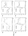
- Figur 3 mehrere Phasenkennlinien von erfindungsgemäß ausgeführten Phasendetektoren und
- Figur 4 mehrere Phasenkennlinien von Standard-Phasenfehlerdetektoren.
- In der Figur 1 ist ein prinzipielles Blockschaltbild eines QAM-Empfängers dargestellt. Der QAM-Empfänger besteht aus einem Inphasen-Signalzweig und einem Quadraturphasen-Signalzweig. Im Inphasen-Signalzweig befindet sich ein Mischer MI und im Quadraturphasen-Signalzweig ein Mischer MQ. Diese beiden Mischer MI und MQ setzen das Empfangssignal ES, das auf die beiden Signalzweige aufgeteilt wird, ins Basisband um. Die Referenzfrequenz für die beiden Mischer MI und MQ wird von einem spannungsgesteuerten Oszillator VCO geliefert. Einem der beiden Mischer wird das vom spannungsgesteuerten Oszillator VCO erzeugte Referenzfrequenzsignal einem 90°-Phasenschieber PS zugeführt, so daß die Referenzfrequenzen für die beiden Mischer MI und MQ eine gegenseitige Phasenablage von 90° aufweisen. Das Ausgangssignal des Mischers MI, das die Inphasen-Signalkomponente ZI eines Empfangssignalzustandes darstellt, und das Ausgangssignal des Mischers MQ, das die Quadraturphasen-Signalkomponente ZQ eines Empfangssignalzustandes darstellt, werden einem Phasenfehlerdetektor PFD zugeführt. Dieser Phasenfehlerdetektor PFD, erzeugt, wie nachfolgend noch detailliert beschrieben, ein Phasenkorrektursignal S, das als Steuersignal für den spannungsgesteuerten Oszillator VCO dient.
- Anhand der nachfolgenden Gleichungen soll verdeutlicht werden, wie der Phasenfehlerdetektor aus den einzelnen Empfangssignalzuständen mit der Inphasen-Signalkomponente ZI und der Quadraturphasen-Signalkomponente ZQ das Phasenkorrektursignal S, das die Ablage der Trägerphase des Empfangssignals gegenüber der Phase des vom spannungsgesteuerten Oszillator VCO erzeugten Referenzfrequenzsignals darstellt, ermittelt. Der Phasenfehlerdetektor PFD berechnet nach einer weit verbreiteten Methode das Phasenkorrektursignal S gemäß der Gleichung (1).

- Dabei sind FI und FQ Entscheiderfehler, die, wie die Gleichung (2) ausdrückt, die Ablagen der Inphasen-Signalkomponente ZI und der Quadraturphasen-Signalkomponente ZQ des Empfangssignalzustandes gegenüber der Inphasen-Komponente AI und der Quadraturphasen-Komponente AQ desjenigen QAM-Signalzustandes sind, für den der Phasenfehlerdetektor PFD entschieden hat, daß dieser der von einem Sender abgegebene Sendesignalzustand ist.

- Bei einer Übertragung des Sendesignal zustands ohne Verzerrungen ist der Empfangssignalzustand Z = ZI + jZQ lediglich um einen Winkel ϕ gegenüber dem Sendesignalzustand A = AI + jAQ verdreht. Dies drückt die Gleichung (3) aus.

- Häufig wird zur Berechnung des Phasenkorrektursignals nicht die in Gleichung (1) angegebene Funktion sondern die Signumsversion gemäß Gleichung (4) verwendet, welche keine aufwendigen Multiplikationen benötigt.

- Die statische Phasenkennlinie ist der Mittelwert über alle möglichen QAM-Sendesignalzustände, wie in Gleichung (5) angegeben.

- Wegen Gleichung (2) gilt für die Quadraturkomponenten des Entscheiderfehlers:

- Mit (6) gilt für das Phasenkorrektursignal S gemäß (1).

- Mit diesem Phasenkorrektursignal erhält man mit E 〈A2〉 = 1 eine statische Phasenkennlinie gemäß Gleichung (8).

- Diese Berechnung der statischen Phasenkennlinie unterstellt allerdings die Gültigkeit der Gleichung (2), also eine fehlerfreie Zuordnung der Empfangssignalzustände zu Sendesignalzuständen. Für QAM-Signalkonstellationen bedeutet dies einen eingeschränkten und vom Modulationsverfahren abhängigen Gültigkeitsbereich der Phasenkennlinie gemäß Gleichung (8), beispielsweise [-45°, + 45°] für 4-QAM, [-16,5°, + 16,5°] für 16-QAM usw.
- Phasenkennlinien entsprechend der Signumversion nach Gleichung (4) besitzen im Gültigkeitsbereich keinen sinusförmigen sondern einen linearen Verlauf. In der Figur 4 sind Phasenkennlinien für 16-QAM, 32-QAM, 64-QAM und 128-QAM Empfänger dargestellt, welche das Phasenkorrektursignal standardgemäß nach Gleichung (5) berechnen. Bei allen vier Modulationsverfahren sind unerwünschte Nullstellen, d.h. falsche Einrastpunkte vorhanden; am deutlichsten sind sie bei 22-QAM erkennbar. Bei diesem Modulationsverfahren werden auch die längsten Verweildauern in unerwünschten Phasenlagen festgestellt.
- Um die unerwünschten Nulldurchgänge in der Phasenkennlinie zu vermeiden, stehen dem Phasenfehlerdetektor fünf verschiedende Berechnungsmethoden für das Phasenkorrektursignal zur Verfügung:

- In den vier Berechnungsmethoden S1 bis S4 kann für die Funktionen f (ZI) und f (ZQ) gelten:
- f(ZI) = ZI und f(ZQ) = ZQ
oder - f(ZI) = sign(ZI) und f(ZQ) = sign(ZQ)
- In welchem Fall welche der fünf Berechnungsmethoden S1 bis S5 für das Phasenkorrektursignal vom Phasenfehlerdetektor verwendet wird, hängt davon ab, in welches Entscheidergebiet welchen QAM-Signalzustandes ein komplexer in seine Inphasen-Signalkomponente ZI und seine Quadraturphasen-signalkomponente ZQ zerlegter Empfangssignalzustand fällt.
- Bei der Zuordnung der Berechnungsmethoden S1 bis S5 zu den einzelnen Entscheidergebieten werden die Anteile aller Sendesymbole an der statischen Phasenkennlinie einzeln betrachtet. So gibt es z. B. bei einer 16-QAM Modulation genau 16 verschiedene Sendesymbole A(i), i = 1...16, und dami 16 Anteile S(i), welche im Mittel dann die statische Phasenkennlinie S bilden:

- Um für die Phasenkenlinie S einen günstigen Verlauf zu erhalten, werden in einem ersten Schritt diejenigen Sendesymbole A(i) identifiziert, welche für positive Winkel ϕ>0 einen negativen Bereich S(i)<0 besitzen oder für negative Winkel einen positiven Bereich. Hierbei wird zunächst für alle Entscheidergebiete die Methode S1, also die Standardmethode, unterstellt. Diese Bereiche führen dann in Gleichung (10) zu den unerwünschten Nullstellen im Gesamtverhalten der Phasenkorrekturkennlinie S. In einem zweiten Schritt werden dann diejenigen Entscheidergebiete ermittelt, die bei dem entsprechenden Sendesymbol A(i) die unerwünschte Korrekturinformation liefern. In einem dritten Schritt kann schließlich getestet werden, ob eine der Methoden S2 oder S3 eine gewünschte Verbesserung bring. Nach Bearbeitung aller Sendesymbole und aller Entscheidergebiete wird sich in der Regel eine Verbesserung des Verlaufs der Phasenkennlinie eingestellt haben. Es kann aber sein, daß die Verbesserung aber noch unzureichend ist. Für die verbleibenden Bereiche S(i)<0 für ϕ>0 respektive S(i)>0 für ϕ<0 werden dann die Methoden S4 und S5 eingesetzt, wobei aber nur soviele Entscheidergebiete ausgewählt werden, bis die unerwünschten Nullstellen in der Phasenkennlinie zuverlässig verschwunden sind. Die Methoden S4 und S5 werden deshalb so zurückhaltend eingesetzt, weil sie eine - wenn auch geringfügige - Deformation der statischen Phasenkennlinie im Einrastpunkt bewirken. Das hier beschriebene Verfahren wird zweckmäßigerweise rechnergestützt durchgeführt, wobei aber auch einige Entscheidungen empirisch zu fällen sind.
- In der Figur 2 ist beispielsweise die komplexe Signalzustandsebene eines 16-QAM-Systems dargestellt. Auf der Abszisse des Koordinatensystems der komplexen QAM-Signalzustandsebene laufen die Indizes I der Inphasen-Signalkomponente von 0 bis 4 und auf der Ordinate des Koordinatensystems laufen die Indizes Q der Quadraturphasen-Signalkomponenten ebenfalls von 0 bis 4. Die sechzehn quadratischen Punkte in der Signalzustandsebne entsprechen den 16-QAM-Sendesignalzuständen, und die drei dünnen konzentrischen Kreise, auf denen die quadratischen Punkte liegen, sind die Spuren der Empfangssignalzustände bei fehlender Trägerphasensynchronisation. Die Quadrate, welche die Signalzustände (quadratische Punkte) umgeben, werden als Entscheidergebiete bezeichnet. Der Phasenfehlerdetektor PFD ermittelt nämlich durch Schwellwertentscheidung, in welches Entscheidergebiet welchen QAM-Signalzustandes ein komplexes in seine Inphasen-Signalkomponente ZI und in seine Quadratur-Signalkomponente ZQ zerlegter Empfangssignalzustand fällt. Die Richtung und die Stärke der vom Phasenfehlerdetektor berechneten Phasenkorrekturinformation wird durch die Farbe (schwarz, weiß) und die Größe der in Figur 2 eingezeichneten Kreise dargestellt. Schwarze Kreise bewirken eine Phasenkorrektur in positiver Richtung (entgegen dem Uhrzeigersinn) und weiße Kreise in negativer Richtung (im Uhrzeigersinn). Große Kreise entsprechen einer starken Korrektur, kleine Kreise einer schwachen Korrektur. In den acht mit 0 gekennzeichneten Feldern wird überhaupt keine Korrekturinformatioon erzeugt (entspricht der Methode S5).
- Die dick umrandeten Entscheidergebiete in Figur 2 erfahren gegenüber der bekannten standardisierten Phasenfehlerdetektion eine Modifikation. Für sie werden nämlich unterschiedliche Berechnungsmethoden gemäß Gleichung (9) für das Phasenkorrektursignal angewendet. Die Indizes I und Q, welche die Lage der Entscheidergebiete beschreiben, sind in der nachfolgenden Tabelle im Abschnitt 16-QAM wiedergegeben. Außerdem ist zu jedem Entscheidergebiet, also zu jeder Kombination I/Q, die aus den fünf Rechenmethoden S1 bis S5 ausgewählte Rechenmethode aufgeführt. Dort wird beispielsweise für die Entscheidergebiete 0/3 und 3/0 der Wert 0 gefordert, das entspricht der Methode S5. In den Gebieten 0/4, 1/4, 4/0 und 4/1 ist die Korrekturinformation konstant; das entspricht der Berechnungsmethode S4. In den beiden Entscheidergebieten 1/3 und 3/1 ist die Phasenkorrekturinformation nur von einem Entscheiderfehler FI oder FQ abhängig, was in der Figur 2 durch eine achsenparallele Orientierung der Punktgröße zum Ausdruck kommt; hier kommen die Berechnungsmethoden S2 und S3 zum Tragen.
- Warum die vorangehend beschriebene Auswahl aus verschiedenen Berechnungsmethoden S1 bis S5 für das Phasenkorrektursignal eine Verbesserung der statischen Phasenkennlinie unerwünschter Nullstellen bringt, kann folgendermaßen erklärt werden:
- Die vier äußeren Entscheidergebiete 0/4, 1/4, 4/0 und 4/1 sind eindeutig in der Phasenkorrekturinformation. Es macht daher Sinn, für diese Fälle den maximalen durch den Aussteuerbereich festgelegten Wert zu wählen. Allerdings dürfen nicht alle Entscheidergebiete, deren Korrekturinformation eindeutig ist, auf diese Weise behandelt werden, denn der Verlauf der statischen Phasenkennlinie soll in der Nähe des Ursprungs so wenig wie möglich verfälscht werden (endliche Steigung der Phasenkennlinie im Einrastpunkt ϕ = 0). Aus diesem Grund bleiben beispielsweise die Gebiete 0/1 und 1/0 unverändert.
- Die Bereiche 0/3 und 3/0 liefern für bestimmte Phasen falsche Korrekturinformationen, da auf dem mittleren Kreis eine hohe Unsicherheit bezüglich des tatsächlich gesendeten Signalzustandes besteht. Die Ausblendung dieser Entscheidergebiete ist zwingend, Dementsprechend sind diese Bereiche in der Figur 2, für die die Berechnungsmethode S5 in Frage kommt, mit einer Null gekennzeichnet.
- Die beiden Gebiete 1/3 und 3/1 werden entweder in der Einrastphase von einem rotierenden Eckpunkt oder in der Nachführphase von einem benachbarten verrauschten Empfangssignalzustand getroffen. Im ersten Fall liefern diese Entscheidergebiete eine korrekte Phasenkorrekturinformation und im zweiten Fall eine unbedeutende. Damit diese Entscheidergebiete also im ersten Fall eine möglichst hohe und im zweiten Fall eine möglichst geringe Phasenkorrekturinformation liefern, wird jeweils nur eine Quadraturkomponente FI oder FQ des Entscheiderfehlers gemäß den Berechnungsmethoden S2 oder S3 ausgewertet.
- Der nachfolgenden Tabelle können ebenfalls für 32-QAM, 64-QAM und 128-QAM Systeme die Zuordnungen der Entscheidergebiete zu den einzelnen Berechnungsmethoden S1 bis S5 entnommen werden.
16-QAM Index I Index Q Methode 3 0 S5 0 3 S5 3 1 S3 1 3 S2 4 0 S4 0 4 S4 4 1 S4 1 4 S4 Alle übrigen Alle übrigen S1 32-QAM Index I Index Q Methode 3 0 S5 0 3 S5 4 0 S3 0 4 S2 4 2 S3 2 4 S2 5 1 S3 1 5 S2 5 2 S4 2 5 S4 Alle übrigen Alle übrigen S1 64-QAM Index I Index Q Methode 3 0 S5 0 3 S5 4 0 S3 0 4 S2 4 2 S3 2 4 S2 5 1 S3 1 5 S2 5 2 S4 2 5 S4 7 3 S3 3 7 S2 8 2, 3, 4, 5 S4 2, 3, 4, 5 8 S4 9 0, 1, 2, 3, 4 S4 0, 1, 2, 3, 4 9 S4 Alle übrigen Alle übrigen S1 128-QAM Index I Index Q Methode 3 0 S5 0 3 S5 4 0 S3 0 4 S2 4 2 S3 2 4 S2 5 1 S3 1 5 S2 5 2 S4 2 5 S4 7 3 S3 3 7 S2 8 5 S5 5 8 S5 9 3 S3 3 9 S2 9 7 S5 7 9 S5 9 8 S5 8 9 S5 10 2 S5 2 10 S5 10 7 S5 7 10 S5 10 8 S5 8 10 S5 11 5 S3 5 11 S2 11 6 S4 6 11 S4 12 3 S4 3 12 S4 12 4 S4 4 12 S4 Alle übrigen Alle übrigen 1 - Mit den dargestellten Zuordnungen der verschiedenen Berechnungsmethoden S1 bis S5 für das Phasenkorrektursignal ergeben sich für das 16-QAM, das 32-QAM, das 64-QAM und das 128-QAM-System die in der Figur 3 dargestellten Phasenkennlinien, die einen im Einrastpunkt ϕ = 0 unveränderten Verlauf haben und keine unerwünschten Nullstellen mehr aufweisen.
Claims (3)
- Phasenfehlerdetektor für einen QAM-Empfänger, in dem alle vorkommenden QAM-Signalzustände abgespeichert sind und dabei jeder der in einer komplexen Signalzustandsebene liegenden QAM-Signalzustände von einem Entscheidergebiet umgeben ist und der Phasenfehlerdetektor durch Schwellwertentscheidungen detektiert, in welches Entscheidergebiet welchen QAM-Signalzustandes ein komplexes in seine Inphasen (ZI) und seine Quadraturphasen-Signalkomponente (ZQ) zerlegter Empfangssignalzustand fällt, und er in Abhängigkeit vom detektierten Entscheidergebiet ein Phasenkorrektursignal (S) für die Trägerphase des Empfangssignals (ES) bildet, dadurch gekennzeichnet,- daß der Phasenfehlerdetektor (PFD) das Phasenkorrektursignal (S) je nach detektiertem Entscheidergebiet nach einem der folgenden Methoden berechnet:





wobei ZI und ZQ die Inphasen- und die Quadraturphasen-signalkomponente des Empfangssignalzustands sind und FI und FQ die Ablagen von ZI und ZQ gegenüber der Inphasen- und Quadraturphasen-Komponente des entschiedenen QAM-Signalzustandes sind,- und daß der Phasenfehlerdetektor (PFD) eine solche Zuordnung zwischen den Entscheidergebieten und den einzelnen Berechnungsmethoden (S1 bis S5) trifft, daß seine statische Phasenkennlinie außer beim Einrastpunkt, in dem die Phasenablage zwischen dem Referenzträger des Empfängers und dem Empfangssignalträger 0 ist, keine weitere Nullstelle aufweist. - Phasenfehlerdetektor nach Anspruch 1, dadurch gekennzeichnet, daß für die Berechnungsmethoden (S1 bis S3) gilt: f(ZI) = ZI und f (ZQ) = ZQ.
- Phasenfehlerdetektor nach Anspruch 1, dadurch gekennzeichnet, daß für die Berechnungsmethoden S1 bis S5 gilt: f(ZI) = sign(ZI) und f (ZQ) = sign(ZQ).
Applications Claiming Priority (3)
| Application Number | Priority Date | Filing Date | Title |
|---|---|---|---|
| DE19928206 | 1999-06-19 | ||
| DE19928206A DE19928206A1 (de) | 1999-06-19 | 1999-06-19 | Phasenfehlerdetektor für einen QAM-Empfänger |
| PCT/IB2000/000809 WO2000079754A1 (de) | 1999-06-19 | 2000-06-08 | Phasenfehlerdetektor für einen qam-empfänger |
Publications (2)
| Publication Number | Publication Date |
|---|---|
| EP1190544A1 EP1190544A1 (de) | 2002-03-27 |
| EP1190544B1 true EP1190544B1 (de) | 2007-09-12 |
Family
ID=7911905
Family Applications (1)
| Application Number | Title | Priority Date | Filing Date |
|---|---|---|---|
| EP00931510A Expired - Lifetime EP1190544B1 (de) | 1999-06-19 | 2000-06-08 | Phasenfehlerdetektor für einen qam-empfänger |
Country Status (8)
| Country | Link |
|---|---|
| US (1) | US7283599B1 (de) |
| EP (1) | EP1190544B1 (de) |
| CN (1) | CN1149805C (de) |
| AT (1) | ATE373371T1 (de) |
| AU (1) | AU4945800A (de) |
| DE (2) | DE19928206A1 (de) |
| NO (1) | NO20016204L (de) |
| WO (1) | WO2000079754A1 (de) |
Families Citing this family (15)
| Publication number | Priority date | Publication date | Assignee | Title |
|---|---|---|---|---|
| WO2000015130A2 (en) | 1998-09-10 | 2000-03-23 | Scimed Life Systems, Inc. | Systems for controlling an ablation process performed with a heart electrocatheter |
| DE10249492A1 (de) * | 2002-10-24 | 2004-05-13 | Micronas Gmbh | Verfahren und Schaltung zur Erzeugung eines Hilfssymbols zum Einregeln eines QAM-Demodulators |
| DE10347259B4 (de) * | 2003-10-08 | 2013-10-31 | Entropic Communications, Inc. | Verfahren zum Synchronisieren einer Schaltungsanordnung beim Empfang eines modulierten Signals |
| JP4541403B2 (ja) * | 2004-03-22 | 2010-09-08 | トムソン ライセンシング | 通信システムにおける搬送波再生で使われる方法および装置 |
| DE102004023889A1 (de) | 2004-05-12 | 2005-12-08 | Micronas Gmbh | Verfahren und Schaltungsanordnung zum Bestimmen der Frequenz eines empfangenen Signals zum Demodulieren von empfangenen Symbolen |
| US9571326B2 (en) | 2009-03-05 | 2017-02-14 | SeeScan, Inc. | Method and apparatus for high-speed data transfer employing self-synchronizing quadrature amplitude modulation |
| US8259859B2 (en) * | 2009-09-21 | 2012-09-04 | Techwell Llc | Method and system for carrier recovery for QAM |
| US20120163523A1 (en) * | 2010-12-22 | 2012-06-28 | Smith International, Inc. | Synchronization methods for downhole communication |
| CN102185824B (zh) * | 2011-04-25 | 2014-04-16 | 武汉邮电科学研究院 | 一种适用于高阶qam的载波相位纠偏方法 |
| US9634878B1 (en) | 2011-09-08 | 2017-04-25 | See Scan, Inc. | Systems and methods for data transfer using self-synchronizing quadrature amplitude modulation (QAM) |
| US10447513B2 (en) * | 2017-01-06 | 2019-10-15 | National Instruments Corporation | Common phase error (CPE) compensation for frequency division multiplex (FDM) symbols in wireless communication systems |
| WO2018187155A1 (en) | 2017-04-03 | 2018-10-11 | National Instruments Corporation | Wireless communication system that performs measurement based selection of phase tracking reference signal (ptrs) ports |
| WO2018204571A1 (en) | 2017-05-05 | 2018-11-08 | National Instruments Corporation | Wireless communication system that performs beam reporting based on a combination of reference signal receive power and channel state information metrics |
| US10951300B2 (en) | 2017-08-11 | 2021-03-16 | National Instruments Corporation | Radio frequency beam management and recovery |
| US12362983B2 (en) * | 2023-02-15 | 2025-07-15 | Qualcomm Incorporated | Zero-crossing-avoidance encoding for quadrature amplitude modulation |
Family Cites Families (7)
| Publication number | Priority date | Publication date | Assignee | Title |
|---|---|---|---|---|
| DE3619744A1 (de) * | 1986-06-12 | 1987-12-17 | Ant Nachrichtentech | Verfahren zum gewinnen eines phasendifferenzsignals |
| FR2621188B1 (fr) * | 1987-09-25 | 1989-12-29 | Labo Electronique Physique | Circuit de recuperation de l'onde porteuse de systemes de transmissions numeriques |
| US5042052A (en) * | 1990-02-16 | 1991-08-20 | Harris Corporation | Carrier acquisition scheme for QAM and QPSK data |
| US5640417A (en) * | 1991-10-04 | 1997-06-17 | Harris Canada, Inc. | QAM detector which compensates for received symbol distortion induced by a cellular base station |
| DE4216156C1 (de) | 1992-05-15 | 1993-08-19 | Ant Nachrichtentechnik Gmbh, 7150 Backnang, De | |
| US5504453A (en) * | 1994-10-14 | 1996-04-02 | Hughes Aircraft Company | Method and device for estimating phase error |
| JPH09214578A (ja) * | 1996-01-30 | 1997-08-15 | Fujitsu Ltd | 搬送波再生回路 |
-
1999
- 1999-06-19 DE DE19928206A patent/DE19928206A1/de not_active Withdrawn
-
2000
- 2000-06-08 WO PCT/IB2000/000809 patent/WO2000079754A1/de not_active Ceased
- 2000-06-08 US US10/018,759 patent/US7283599B1/en not_active Expired - Lifetime
- 2000-06-08 CN CNB008117616A patent/CN1149805C/zh not_active Expired - Fee Related
- 2000-06-08 AU AU49458/00A patent/AU4945800A/en not_active Abandoned
- 2000-06-08 EP EP00931510A patent/EP1190544B1/de not_active Expired - Lifetime
- 2000-06-08 DE DE50014653T patent/DE50014653D1/de not_active Expired - Lifetime
- 2000-06-08 AT AT00931510T patent/ATE373371T1/de not_active IP Right Cessation
-
2001
- 2001-12-18 NO NO20016204A patent/NO20016204L/no not_active Application Discontinuation
Also Published As
| Publication number | Publication date |
|---|---|
| NO20016204D0 (no) | 2001-12-18 |
| AU4945800A (en) | 2001-01-09 |
| DE19928206A1 (de) | 2000-12-21 |
| US7283599B1 (en) | 2007-10-16 |
| WO2000079754A1 (de) | 2000-12-28 |
| DE50014653D1 (de) | 2007-10-25 |
| EP1190544A1 (de) | 2002-03-27 |
| CN1370366A (zh) | 2002-09-18 |
| CN1149805C (zh) | 2004-05-12 |
| ATE373371T1 (de) | 2007-09-15 |
| NO20016204L (no) | 2002-02-19 |
Similar Documents
| Publication | Publication Date | Title |
|---|---|---|
| DE3689499T2 (de) | Schaltung zur automatischen Verstärkungsregelung. | |
| DE68916289T2 (de) | Direktmisch-Empfänger. | |
| DE69736188T2 (de) | Verfahren in einem digitalen quadraturmodulator und -demodulator sowie digitaler quadraturmodulator und -demodulator | |
| DE69215298T2 (de) | PSK-Demodulator mit Korrektur im Basisband für Phasen- oder Frequenzfehler | |
| DE69737174T2 (de) | Trägerrückgewinnung in einem QAM-Empfänger | |
| DE69407512T2 (de) | Verfahren und Anordnung zur automatischen Erkennung der Konstellationsgrösse eines QAM-Signals | |
| DE2309167C2 (de) | Verfahren und Schaltungsanordnung zum Korrigieren eines durch Phasenzittern verfälschten elektrischen Übertragtungssignals | |
| DE19928206A1 (de) | Phasenfehlerdetektor für einen QAM-Empfänger | |
| EP0895386B1 (de) | Trägerregelkreis für einen Empfänger von digital übertragenen Signalen | |
| DE69519646T2 (de) | Verfahren und Einrichtung zur Trägerrückgewinnung für ein QAM-moduliertes Signal | |
| EP1592164B1 (de) | Verfahren und Schaltungsanordnung zum Bestimmen eines Taktsignal-Abtastzeitpunkts für Symbole eines Modulationsverfahrens | |
| DE19535839B4 (de) | Automatischer Amplitudenentzerrer | |
| EP0249045B1 (de) | Verfahren zum Gewinnen eines Phasendifferenzsignals | |
| DE69729329T2 (de) | Gerät und verfahren zur phasenschätzung | |
| DE3855264T2 (de) | QAM Modulator | |
| DE19509818A1 (de) | Funkempfänger zur Verwendung beim Empfang von digitalen Multiplexsignalen | |
| DE102009030675B4 (de) | Verfahren und Vorrichtung zum Senden und Empfangen von Signalen mit Modulationskompression | |
| EP0281652A1 (de) | Verfahren zum Gewinnen eines Phasendifferenzsignals | |
| DE68928362T2 (de) | Digitale selbsttätige Frequenzsteuerung mit reinen Sinuswellen | |
| DE69531025T2 (de) | Genaue Erkennung eines Frequenzfehlers für mit einer vorbestimmten Symbolfolge modulierte Bursts | |
| EP1523144A2 (de) | Verfahren und Schaltungsanordnung zum Entscheiden eines Symbols im komplexen Phasenraum eines Quadratumodulationsverfahrens | |
| DE69426029T2 (de) | Filter höherer ordnung für digitale phasenschleife | |
| DE3938643C2 (de) | Verfahren zum Rekonstruieren abgetrennter Gleichspannungsnutzanteile an ZF-Signalen in einem Direct-Conversion-Empfänger und Empfänger zum Durchführen des Verfahrens | |
| DE102006017937B4 (de) | Verfahren und Kalibrierungssytem für IQ-Gleichspannungsoffset- und Unsymmetrie-Kalibrierung durch Verwendung von analytischen Formeln, um gewünschte Kompensationswerte schnell zu bestimmen | |
| DE2452487A1 (de) | Phasendemodulator |
Legal Events
| Date | Code | Title | Description |
|---|---|---|---|
| PUAI | Public reference made under article 153(3) epc to a published international application that has entered the european phase |
Free format text: ORIGINAL CODE: 0009012 |
|
| 17P | Request for examination filed |
Effective date: 20020104 |
|
| AK | Designated contracting states |
Kind code of ref document: A1 Designated state(s): AT BE CH CY DE DK ES FI FR GB GR IE IT LI LU MC NL PT SE |
|
| AX | Request for extension of the european patent |
Free format text: AL;LT;LV;MK;RO;SI |
|
| 17Q | First examination report despatched |
Effective date: 20061106 |
|
| RAP1 | Party data changed (applicant data changed or rights of an application transferred) |
Owner name: ERICSSON AB |
|
| GRAP | Despatch of communication of intention to grant a patent |
Free format text: ORIGINAL CODE: EPIDOSNIGR1 |
|
| GRAS | Grant fee paid |
Free format text: ORIGINAL CODE: EPIDOSNIGR3 |
|
| GRAA | (expected) grant |
Free format text: ORIGINAL CODE: 0009210 |
|
| AK | Designated contracting states |
Kind code of ref document: B1 Designated state(s): AT BE CH CY DE DK ES FI FR GB GR IE IT LI LU MC NL PT SE |
|
| REG | Reference to a national code |
Ref country code: GB Ref legal event code: FG4D Free format text: NOT ENGLISH |
|
| REG | Reference to a national code |
Ref country code: CH Ref legal event code: EP |
|
| REF | Corresponds to: |
Ref document number: 50014653 Country of ref document: DE Date of ref document: 20071025 Kind code of ref document: P |
|
| REG | Reference to a national code |
Ref country code: IE Ref legal event code: FG4D Free format text: LANGUAGE OF EP DOCUMENT: GERMAN |
|
| GBT | Gb: translation of ep patent filed (gb section 77(6)(a)/1977) |
Effective date: 20071031 |
|
| PG25 | Lapsed in a contracting state [announced via postgrant information from national office to epo] |
Ref country code: FI Free format text: LAPSE BECAUSE OF FAILURE TO SUBMIT A TRANSLATION OF THE DESCRIPTION OR TO PAY THE FEE WITHIN THE PRESCRIBED TIME-LIMIT Effective date: 20070912 |
|
| PG25 | Lapsed in a contracting state [announced via postgrant information from national office to epo] |
Ref country code: ES Free format text: LAPSE BECAUSE OF FAILURE TO SUBMIT A TRANSLATION OF THE DESCRIPTION OR TO PAY THE FEE WITHIN THE PRESCRIBED TIME-LIMIT Effective date: 20071223 Ref country code: GR Free format text: LAPSE BECAUSE OF FAILURE TO SUBMIT A TRANSLATION OF THE DESCRIPTION OR TO PAY THE FEE WITHIN THE PRESCRIBED TIME-LIMIT Effective date: 20071213 |
|
| REG | Reference to a national code |
Ref country code: IE Ref legal event code: FD4D |
|
| ET | Fr: translation filed | ||
| PG25 | Lapsed in a contracting state [announced via postgrant information from national office to epo] |
Ref country code: PT Free format text: LAPSE BECAUSE OF FAILURE TO SUBMIT A TRANSLATION OF THE DESCRIPTION OR TO PAY THE FEE WITHIN THE PRESCRIBED TIME-LIMIT Effective date: 20080212 |
|
| PG25 | Lapsed in a contracting state [announced via postgrant information from national office to epo] |
Ref country code: SE Free format text: LAPSE BECAUSE OF FAILURE TO SUBMIT A TRANSLATION OF THE DESCRIPTION OR TO PAY THE FEE WITHIN THE PRESCRIBED TIME-LIMIT Effective date: 20071212 |
|
| PLBE | No opposition filed within time limit |
Free format text: ORIGINAL CODE: 0009261 |
|
| STAA | Information on the status of an ep patent application or granted ep patent |
Free format text: STATUS: NO OPPOSITION FILED WITHIN TIME LIMIT |
|
| PG25 | Lapsed in a contracting state [announced via postgrant information from national office to epo] |
Ref country code: DK Free format text: LAPSE BECAUSE OF FAILURE TO SUBMIT A TRANSLATION OF THE DESCRIPTION OR TO PAY THE FEE WITHIN THE PRESCRIBED TIME-LIMIT Effective date: 20070912 |
|
| 26N | No opposition filed |
Effective date: 20080613 |
|
| PGFP | Annual fee paid to national office [announced via postgrant information from national office to epo] |
Ref country code: IT Payment date: 20080625 Year of fee payment: 9 |
|
| PG25 | Lapsed in a contracting state [announced via postgrant information from national office to epo] |
Ref country code: IE Free format text: LAPSE BECAUSE OF FAILURE TO SUBMIT A TRANSLATION OF THE DESCRIPTION OR TO PAY THE FEE WITHIN THE PRESCRIBED TIME-LIMIT Effective date: 20070912 |
|
| BERE | Be: lapsed |
Owner name: ERICSSON A.B. Effective date: 20080630 |
|
| PG25 | Lapsed in a contracting state [announced via postgrant information from national office to epo] |
Ref country code: MC Free format text: LAPSE BECAUSE OF NON-PAYMENT OF DUE FEES Effective date: 20080630 |
|
| REG | Reference to a national code |
Ref country code: CH Ref legal event code: PL |
|
| PG25 | Lapsed in a contracting state [announced via postgrant information from national office to epo] |
Ref country code: BE Free format text: LAPSE BECAUSE OF NON-PAYMENT OF DUE FEES Effective date: 20080630 |
|
| PG25 | Lapsed in a contracting state [announced via postgrant information from national office to epo] |
Ref country code: LI Free format text: LAPSE BECAUSE OF NON-PAYMENT OF DUE FEES Effective date: 20080630 Ref country code: CH Free format text: LAPSE BECAUSE OF NON-PAYMENT OF DUE FEES Effective date: 20080630 |
|
| PG25 | Lapsed in a contracting state [announced via postgrant information from national office to epo] |
Ref country code: CY Free format text: LAPSE BECAUSE OF FAILURE TO SUBMIT A TRANSLATION OF THE DESCRIPTION OR TO PAY THE FEE WITHIN THE PRESCRIBED TIME-LIMIT Effective date: 20070912 |
|
| PG25 | Lapsed in a contracting state [announced via postgrant information from national office to epo] |
Ref country code: AT Free format text: LAPSE BECAUSE OF NON-PAYMENT OF DUE FEES Effective date: 20080608 |
|
| PG25 | Lapsed in a contracting state [announced via postgrant information from national office to epo] |
Ref country code: LU Free format text: LAPSE BECAUSE OF NON-PAYMENT OF DUE FEES Effective date: 20080608 |
|
| PG25 | Lapsed in a contracting state [announced via postgrant information from national office to epo] |
Ref country code: IT Free format text: LAPSE BECAUSE OF NON-PAYMENT OF DUE FEES Effective date: 20090608 |
|
| PGFP | Annual fee paid to national office [announced via postgrant information from national office to epo] |
Ref country code: GB Payment date: 20140627 Year of fee payment: 15 |
|
| PGFP | Annual fee paid to national office [announced via postgrant information from national office to epo] |
Ref country code: DE Payment date: 20140627 Year of fee payment: 15 |
|
| PGFP | Annual fee paid to national office [announced via postgrant information from national office to epo] |
Ref country code: FR Payment date: 20140617 Year of fee payment: 15 |
|
| REG | Reference to a national code |
Ref country code: DE Ref legal event code: R119 Ref document number: 50014653 Country of ref document: DE |
|
| GBPC | Gb: european patent ceased through non-payment of renewal fee |
Effective date: 20150608 |
|
| REG | Reference to a national code |
Ref country code: FR Ref legal event code: ST Effective date: 20160229 |
|
| PG25 | Lapsed in a contracting state [announced via postgrant information from national office to epo] |
Ref country code: DE Free format text: LAPSE BECAUSE OF NON-PAYMENT OF DUE FEES Effective date: 20160101 Ref country code: GB Free format text: LAPSE BECAUSE OF NON-PAYMENT OF DUE FEES Effective date: 20150608 |
|
| PG25 | Lapsed in a contracting state [announced via postgrant information from national office to epo] |
Ref country code: FR Free format text: LAPSE BECAUSE OF NON-PAYMENT OF DUE FEES Effective date: 20150630 |
|
| PGFP | Annual fee paid to national office [announced via postgrant information from national office to epo] |
Ref country code: NL Payment date: 20180626 Year of fee payment: 19 |
|
| REG | Reference to a national code |
Ref country code: NL Ref legal event code: MM Effective date: 20190701 |
|
| PG25 | Lapsed in a contracting state [announced via postgrant information from national office to epo] |
Ref country code: NL Free format text: LAPSE BECAUSE OF NON-PAYMENT OF DUE FEES Effective date: 20190701 |