EP1189342A2 - Verstärker, insbesondere Satelliten-Zwischenfrequenz-Verstärker - Google Patents
Verstärker, insbesondere Satelliten-Zwischenfrequenz-Verstärker Download PDFInfo
- Publication number
- EP1189342A2 EP1189342A2 EP01118174A EP01118174A EP1189342A2 EP 1189342 A2 EP1189342 A2 EP 1189342A2 EP 01118174 A EP01118174 A EP 01118174A EP 01118174 A EP01118174 A EP 01118174A EP 1189342 A2 EP1189342 A2 EP 1189342A2
- Authority
- EP
- European Patent Office
- Prior art keywords
- switching
- gain factor
- amplifier
- amplifier according
- operating mode
- Prior art date
- Legal status (The legal status is an assumption and is not a legal conclusion. Google has not performed a legal analysis and makes no representation as to the accuracy of the status listed.)
- Granted
Links
- 230000005540 biological transmission Effects 0.000 claims description 16
- 238000013016 damping Methods 0.000 claims description 9
- 238000011144 upstream manufacturing Methods 0.000 claims 1
- 239000011159 matrix material Substances 0.000 description 7
- 230000010287 polarization Effects 0.000 description 5
- 230000000712 assembly Effects 0.000 description 2
- 238000000429 assembly Methods 0.000 description 2
- 238000005516 engineering process Methods 0.000 description 2
- 230000002787 reinforcement Effects 0.000 description 2
- 230000002238 attenuated effect Effects 0.000 description 1
- 238000010586 diagram Methods 0.000 description 1
- 230000000694 effects Effects 0.000 description 1
- 230000002349 favourable effect Effects 0.000 description 1
- 230000000977 initiatory effect Effects 0.000 description 1
- 238000009434 installation Methods 0.000 description 1
- 238000004519 manufacturing process Methods 0.000 description 1
- 238000005259 measurement Methods 0.000 description 1
- 230000001360 synchronised effect Effects 0.000 description 1
Images

Classifications
-
- H—ELECTRICITY
- H03—ELECTRONIC CIRCUITRY
- H03F—AMPLIFIERS
- H03F3/00—Amplifiers with only discharge tubes or only semiconductor devices as amplifying elements
- H03F3/68—Combinations of amplifiers, e.g. multi-channel amplifiers for stereophonics
-
- H—ELECTRICITY
- H03—ELECTRONIC CIRCUITRY
- H03F—AMPLIFIERS
- H03F3/00—Amplifiers with only discharge tubes or only semiconductor devices as amplifying elements
- H03F3/72—Gated amplifiers, i.e. amplifiers which are rendered operative or inoperative by means of a control signal
-
- H—ELECTRICITY
- H04—ELECTRIC COMMUNICATION TECHNIQUE
- H04N—PICTORIAL COMMUNICATION, e.g. TELEVISION
- H04N7/00—Television systems
- H04N7/20—Adaptations for transmission via a GHz frequency band, e.g. via satellite
Definitions
- the invention relates to an amplifier, in particular a SAT IF amplifier according to the preamble of the claim 1.
- matrix circuits It is in satellite intermediate frequency distribution technology usual, one or connect several matrix circuits. Usually these matrix circuits have at least five inputs and five outputs, namely usually two inputs, above what that about the vertical or horizontal polarization programs broadcast on a higher frequency band as well as two further entrances, via which the vertical or horizontal polarization from a lower frequency band broadcast programs can be received. Via the fifth entrance are those of a terrestrial Antenna received signals forwarded.
- the object of the invention is therefore based on that an improved state of the art To create amplifiers for the different Applications is optimized and with minimal installation effort can be used for different applications.
- the known disadvantages are thereby avoided the amplifier at least two modes of operation having.
- the amplifier is in one operating mode basically - as according to the state of the art known - with a fixed gain factor effective. This is for compensation, for example the effect of three interconnected switching matrices Attenuation adjusted or adjusted accordingly. Installers on site can therefore use the preset Amplifier without problems after every three switching matrices switch on without a re-measurement and leveling is required.
- the Switching device between the two operating modes only through a connectable terminating resistor with preferably 75 ⁇ can be done.
- the gain factor increases by a fixed preset value, for example by 6 dB in the SAT range and for example 4 dB in terrestrial area.
- a trunk section 1 is shown schematically in FIG. 1, via which the programs from a satellite reception system or a headend to a variety of connected Be forwarded to participants.
- trunk line usually five lines, namely 2 x 2 lines 1a to 1d, for example over the lines 1a and 1b are vertical and horizontal Polarization received in an upper frequency band Programs and two further lines 1c and 1d which has a vertical and horizontal polarization in programs received on a lower frequency band Participants.
- the fifth line 2 are those received by a terrestrial antenna Programs forwarded to participants.
- switching and / or distribution matrices 7 used which are cascaded together can be.
- the distribution is often done per Floor, the trunk line 1, for example a first module 10 consisting of three switching matrices and an IF amplifier 11 connected on the output side consists. This is done via subsequent coaxial lines 13 Connection to a next floor, for example another module or two modules 10 of three each Switching matrices with an IF amplifier connected downstream on the output side 11 are provided, etc.
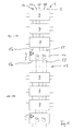
- FIG IF amplifier 11 shown in greater detail, the inner line connected to the trunk line 2 Master route 2 'for the transmission of the terrestrial signals is shown, and according to the in the embodiment Figure 1 provided four trunk routes 1a to 1d Transmission of the vertical and horizontal polarizations received in an upper and lower frequency band Programs only one trunk line 1'a in the amplifier 11 is shown representative. The circuit applies in this respect for the other lines 1'b to 1'd accordingly.
- an adjustable control or level element 19 for variable Adjustment of the gain factor provided and an amplifier stage 23 and a downstream Filter 25 (high pass filter).
- This is adjustable to change the gain factor Control or level element 19 via an adjustment line 29 connected to a switching stage 31.
- This switching stage 31 can be used to set all control or level elements 19 for all four satellite transmission links 1'a to 1'd serve, or there are four such rules or Level elements 19 connected in parallel.
- Both switching stages 31 and 33 are via a trigger line 35 connected to a connector 37 at which a in Figure 2 only indicated termination resistor 39 can be connected is, for example by plugging in or in Form of a screwable terminating resistor.
- the two switching stages are each with two further inputs, at which a fixed resistor 41 or 41 'and a adjustable resistor 43 or 43 'is switched on.
- connection 37 If no terminating resistor 39 is connected to connection 37, if the connection 37 is not connected, so are the two switching stages 31 and 33 in the figure Switched position shown 2, in which the controllable Resistor 43 or 43 'is ineffective. Since only the Fixed resistor 41 or 41 'is effective, is the adjustable control or level 19 only to one accordingly fixed gain factor set.
- This switch position corresponds to the usual one Operating mode that is set to provide damping for example regarding three interconnected Switching matrices 7 with a total attenuation of approx. 9 dB can compensate, ideally again the input conditions before the three switching matrices.
- Deviating from this can now be done through individual adjustment of the adjustable resistors 43 (potentiometer) synchronously the corresponding lines 29 Control or level elements 19 driven and thus the Gain factor for all four SAT transmission paths be changed together and at the same time.
- Gain factor for the terrestrial transmission path can be set.
- FIG. 2 It can also be seen from FIG. 2 that through resistor 43 'and the subsequent switching stage 33 via the downstream adjustment line 49 the corresponding one in the relevant control and level stage 59 Gain factor for the terrestrial transmission path 2 'can be set.
- the internal transmission path 2 ' for the terrestrial transmission path in the normal and Level stage 19, for example two amplifier stages 61 and 63 this internal terrestrial gain path 2 'between the associated input 55 and the output 57 is switched.
- the gain factor can also be used below the gain factor provided in operating mode 1 be lowered downwards.
- the DC voltage can be fed through to all SAT branches become.
- trunk line 1'a (and accordingly in the other regular routes not shown in Amplifier) between the rule and / or level elements 19 and the amplifier 23 is provided with a line equalizer is similar to that in the terrestrial branch 2 ' the control or level element 59 there.
Landscapes
- Engineering & Computer Science (AREA)
- Power Engineering (AREA)
- Physics & Mathematics (AREA)
- Astronomy & Astrophysics (AREA)
- General Physics & Mathematics (AREA)
- Multimedia (AREA)
- Signal Processing (AREA)
- Amplifiers (AREA)
- Input Circuits Of Receivers And Coupling Of Receivers And Audio Equipment (AREA)
- Noise Elimination (AREA)
- Control Of Amplification And Gain Control (AREA)
- Microwave Amplifiers (AREA)
Abstract
- der Verstärker (11) umfasst zumindest zwei Betriebsarten,
- in dem einen Betriebsmodus ist ein bestimmter Verstärkungsfaktor vorgegeben,
- in dem zweiten Betriebsmodus ist der Verstärkungsfaktor mittels einer Einstelleinrichtung (43, 43') veränderlich einstellbar,
- zwischen den beiden Betriebsarten kann mittels einer Umschalteinrichtung umgeschaltet werden, und
- die Umschalteinrichtung besteht aus einem zuschalt- bzw. anschließbaren Abschlusswiderstand (39).
Description
- Figur 1 :
- in schematischer Form eine Stamm-Übertragungsstrecke mit jeweils zwei Modulgruppen bestehend aus drei Umschaltmatrizen mit nachgeschaltetem erfindungsgemäßen ZF-Verstärker; und
- Figur 2 :
- ein schematischer ausschnittsweiser Schaltplan zur Verdeutlichung der Funktionsweise des ZF-Verstärkers.
Claims (8)
- Verstärker, insbesondere SAT-ZF-Verstärker gekennzeichnet durch die folgenden Merkmale:der Verstärker (11) umfasst zumindest zwei Betriebsarten,in dem einen Betriebsmodus ist ein bestimmter Verstärkungsfaktor vorgegeben,in dem zweiten Betriebsmodus ist der Verstärkungsfaktor mittels einer Einstelleinrichtung (43, 43') veränderlich einstellbar,zwischen den beiden Betriebsarten kann mittels einer Umschalteinrichtung umgeschaltet werden, unddie Umschalteinrichtung besteht aus einem zuschalt- bzw. anschließbaren Abschlusswiderstand (39).
- Verstärker nach Anspruch 1, dadurch gekennzeichnet, dass in dem einen Betriebsmodus der vorgegebene Verstärkungsfaktor nicht veränderbar ist.
- Verstärker nach Anspruch 1 oder 2, dadurch gekennzeichnet, dass bei Umschaltung in den zweiten Betriebsmodus mit veränderlich einstellbarem Verstärkungsfaktor ein bestimmter Verstärkungsfaktor werkseitig vorgegeben ist.
- Verstärker nach Anspruch 3, dadurch gekennzeichnet, dass bei Umschaltung in den Betriebsmodus mit veränderlich einstellbarem Verstärkungsfaktor der Verstärkungsfaktor in dem SAT-Übertragungsweg (1'a bis 1'd) unterschiedlich vorgegeben ist zu dem veränderlich einstellbaren Verstärkungsfaktor in dem Übertragungsweg (2) für die terrestrisch empfangenen Programme.
- Verstärker nach einem der Ansprüche 1 bis 4, dadurch gekennzeichnet, dass der Verstärkungsfaktor in dem ersten Betriebsmodus so vorgewählt ist, dass er zum Ausgleich der Dämpfung einer vorgegebenen Anzahl von zusammengeschalteten Umschaltmatrizen (7) angepasst ist, vorzugsweise auf die Dämpfung, die von drei zusammengeschalteten Umschaltmatrizen (7) bewirkt wird.
- Verstärker nach einem der Ansprüche 1 bis 5, dadurch gekennzeichnet, dass zumindest eine Umschaltstufe (31) für die satellitempfangenen Programme und vorzugsweise eine Umschaltgruppe (33) für den terrestrischen Zweig (2') zur Umschaltung zwischen den beiden Betriebsarten vorgesehen ist.
- Verstärker nach Anspruch 6, dadurch gekennzeichnet, dass die Umschaltstufe (31, 33) bei nicht angeschlossenem Abschlusswiderstand (39) sich in einer ersten Schaltstellung befindet, die durch einen eingangsseitig vorgeschalteten Widerstand (41, 41') festgelegt ist, und dass bei angeschlossenem Abschlusswiderstand (39) die Umschaltstufe (31, 33) in ihre zweite Betriebsstufe umgeschaltet ist, in welcher der an dem einen anderen Eingang angeschlossene regelbare Widerstand (Potentiometer 43, 43') wirksam ist.
- Verstärker nach Anspruch 7, dadurch gekennzeichnet, dass durch den regelbaren Widerstand (43, 43') eine in der jeweiligen Verstärkerstrecke (1'a bis 1'd, 2') geschaltete Regel- oder Pegelglied (19, 49) zur Veränderung des Verstärkungsfaktors ansteuerbar ist.
Applications Claiming Priority (2)
| Application Number | Priority Date | Filing Date | Title |
|---|---|---|---|
| DE20013821U DE20013821U1 (de) | 2000-08-10 | 2000-08-10 | Verstärker, insbesondere SAT-ZF-Verstärker |
| DE20013821U | 2000-08-10 |
Publications (3)
| Publication Number | Publication Date |
|---|---|
| EP1189342A2 true EP1189342A2 (de) | 2002-03-20 |
| EP1189342A3 EP1189342A3 (de) | 2003-12-10 |
| EP1189342B1 EP1189342B1 (de) | 2005-02-23 |
Family
ID=7945040
Family Applications (1)
| Application Number | Title | Priority Date | Filing Date |
|---|---|---|---|
| EP01118174A Expired - Lifetime EP1189342B1 (de) | 2000-08-10 | 2001-07-26 | Verstärker, insbesondere Satelliten-Zwischenfrequenz-Verstärker |
Country Status (5)
| Country | Link |
|---|---|
| EP (1) | EP1189342B1 (de) |
| AT (1) | ATE289713T1 (de) |
| DE (2) | DE20013821U1 (de) |
| ES (1) | ES2236097T3 (de) |
| PT (1) | PT1189342E (de) |
Family Cites Families (2)
| Publication number | Priority date | Publication date | Assignee | Title |
|---|---|---|---|---|
| JP2548157B2 (ja) * | 1987-01-09 | 1996-10-30 | ソニー株式会社 | 利得制御回路 |
| JPH09312539A (ja) * | 1996-05-21 | 1997-12-02 | Matsushita Electric Ind Co Ltd | 受信アッテネータ回路 |
-
2000
- 2000-08-10 DE DE20013821U patent/DE20013821U1/de not_active Expired - Lifetime
-
2001
- 2001-07-26 AT AT01118174T patent/ATE289713T1/de active
- 2001-07-26 PT PT01118174T patent/PT1189342E/pt unknown
- 2001-07-26 ES ES01118174T patent/ES2236097T3/es not_active Expired - Lifetime
- 2001-07-26 DE DE50105407T patent/DE50105407D1/de not_active Expired - Lifetime
- 2001-07-26 EP EP01118174A patent/EP1189342B1/de not_active Expired - Lifetime
Also Published As
| Publication number | Publication date |
|---|---|
| DE50105407D1 (de) | 2005-03-31 |
| ATE289713T1 (de) | 2005-03-15 |
| ES2236097T3 (es) | 2005-07-16 |
| EP1189342B1 (de) | 2005-02-23 |
| DE20013821U1 (de) | 2000-10-12 |
| PT1189342E (pt) | 2005-06-30 |
| EP1189342A3 (de) | 2003-12-10 |
Similar Documents
| Publication | Publication Date | Title |
|---|---|---|
| DE69432997T2 (de) | Schalter für Funksendeempfänger | |
| DE2645018C2 (de) | Anlage zur Adaptiventzerrung des Amplitudenganges eines Übertragungskanals | |
| DE69424407T2 (de) | Empfänger mit regelbarem bandpassfilter | |
| DE69734806T2 (de) | Gegengekoppelte Verstärkerschaltung zur Steuerung einer Verstärkung und einer Impedanz in Unabhängigkeit | |
| DE4327117C2 (de) | Einrichtung für eine Antennenanlage zum Verteilen eines Satellitenempfangssignales | |
| DE1130859B (de) | Einstellbarer Kurvenform-Entzerrer zur Daempfungs- und Laufzeitentzerrung von UEbertragungssystemen | |
| EP1189342B1 (de) | Verstärker, insbesondere Satelliten-Zwischenfrequenz-Verstärker | |
| DE2639947A1 (de) | Aktive scheibenantenne fuer kraftfahrzeuge | |
| EP1050920B1 (de) | Quatro-Konverter | |
| EP0496999A2 (de) | Schaltung zum Aufteilen oder Zusammenführen von Hochfrequenzleistung | |
| DE102004006957A1 (de) | Verfahren und Vorrichtung zum Verstärken eines Empfangssignals | |
| EP1639717A1 (de) | Eichleitungs-anordnung | |
| DE3523876C1 (de) | Antennenumschalteinrichtung | |
| DE10063999A1 (de) | Mikrowellen-Dämpfungsglied | |
| EP0512365A1 (de) | Vorrichtung zur gehörrichtigen Lautstärkesteuerung | |
| DE202009018162U1 (de) | Multischalter für Satelliten-Zwischenfrequenz-Verteilung | |
| DE3417670C2 (de) | ||
| EP1775866A1 (de) | Schaltvorrichtung für eine Satelliten-Empfangsanlage | |
| DE60127129T2 (de) | Verstärker mit variabler verstärkung und erhöhter dynamik | |
| DE1512725C3 (de) | Breitbandverstärker mit steuerbarer Verstärkung | |
| DE1015079B (de) | Ringfilterschaltglied zur Verbindung eines oder mehrerer Generatoren (Sender) mit zwei oder mehr Verbrauchern (z.B. Antennen) oder Hilfsverbrauchern | |
| DE102019101888A1 (de) | Konfigurierbares mikroakustisches HF-Filter | |
| DE69028563T2 (de) | Kompensationsvorrichtung für eine Übertragungsleitung eines Fernsehverteilungsnetzes | |
| EP1290805B1 (de) | Mehrband-mobilfunkendgerät und antennen-schalteinrichtung für ein solches | |
| DE968713C (de) | Anordnung fuer die Kompensation der Leitungsdaempfung in den Leitungsverstaerkern von Traegerfrequenzverbindungen |
Legal Events
| Date | Code | Title | Description |
|---|---|---|---|
| PUAI | Public reference made under article 153(3) epc to a published international application that has entered the european phase |
Free format text: ORIGINAL CODE: 0009012 |
|
| AK | Designated contracting states |
Kind code of ref document: A2 Designated state(s): AT BE CH CY DE DK ES FI FR GB GR IE IT LI LU MC NL PT SE TR |
|
| AX | Request for extension of the european patent |
Free format text: AL;LT;LV;MK;RO;SI |
|
| PUAL | Search report despatched |
Free format text: ORIGINAL CODE: 0009013 |
|
| AK | Designated contracting states |
Kind code of ref document: A3 Designated state(s): AT BE CH CY DE DK ES FI FR GB GR IE IT LI LU MC NL PT SE TR |
|
| AX | Request for extension of the european patent |
Extension state: AL LT LV MK RO SI |
|
| RIC1 | Information provided on ipc code assigned before grant |
Ipc: 7H 03F 3/72 A Ipc: 7H 04N 7/10 B |
|
| 17P | Request for examination filed |
Effective date: 20040401 |
|
| 17Q | First examination report despatched |
Effective date: 20040503 |
|
| AKX | Designation fees paid |
Designated state(s): AT BE CH CY DE DK ES FI FR GB GR IE IT LI LU MC NL PT SE TR |
|
| GRAP | Despatch of communication of intention to grant a patent |
Free format text: ORIGINAL CODE: EPIDOSNIGR1 |
|
| GRAS | Grant fee paid |
Free format text: ORIGINAL CODE: EPIDOSNIGR3 |
|
| GRAA | (expected) grant |
Free format text: ORIGINAL CODE: 0009210 |
|
| AK | Designated contracting states |
Kind code of ref document: B1 Designated state(s): AT BE CH CY DE DK ES FI FR GB GR IE IT LI LU MC NL PT SE TR |
|
| PG25 | Lapsed in a contracting state [announced via postgrant information from national office to epo] |
Ref country code: NL Free format text: LAPSE BECAUSE OF FAILURE TO SUBMIT A TRANSLATION OF THE DESCRIPTION OR TO PAY THE FEE WITHIN THE PRESCRIBED TIME-LIMIT Effective date: 20050223 Ref country code: FI Free format text: LAPSE BECAUSE OF FAILURE TO SUBMIT A TRANSLATION OF THE DESCRIPTION OR TO PAY THE FEE WITHIN THE PRESCRIBED TIME-LIMIT Effective date: 20050223 Ref country code: IE Free format text: LAPSE BECAUSE OF FAILURE TO SUBMIT A TRANSLATION OF THE DESCRIPTION OR TO PAY THE FEE WITHIN THE PRESCRIBED TIME-LIMIT Effective date: 20050223 |
|
| REG | Reference to a national code |
Ref country code: GB Ref legal event code: FG4D Free format text: NOT ENGLISH |
|
| REG | Reference to a national code |
Ref country code: CH Ref legal event code: EP |
|
| GBT | Gb: translation of ep patent filed (gb section 77(6)(a)/1977) |
Effective date: 20050223 |
|
| REG | Reference to a national code |
Ref country code: IE Ref legal event code: FG4D Free format text: GERMAN |
|
| REF | Corresponds to: |
Ref document number: 50105407 Country of ref document: DE Date of ref document: 20050331 Kind code of ref document: P |
|
| PG25 | Lapsed in a contracting state [announced via postgrant information from national office to epo] |
Ref country code: DK Free format text: LAPSE BECAUSE OF FAILURE TO SUBMIT A TRANSLATION OF THE DESCRIPTION OR TO PAY THE FEE WITHIN THE PRESCRIBED TIME-LIMIT Effective date: 20050523 Ref country code: GR Free format text: LAPSE BECAUSE OF FAILURE TO SUBMIT A TRANSLATION OF THE DESCRIPTION OR TO PAY THE FEE WITHIN THE PRESCRIBED TIME-LIMIT Effective date: 20050523 Ref country code: SE Free format text: LAPSE BECAUSE OF FAILURE TO SUBMIT A TRANSLATION OF THE DESCRIPTION OR TO PAY THE FEE WITHIN THE PRESCRIBED TIME-LIMIT Effective date: 20050523 |
|
| REG | Reference to a national code |
Ref country code: PT Ref legal event code: SC4A Free format text: AVAILABILITY OF NATIONAL TRANSLATION Effective date: 20050512 |
|
| REG | Reference to a national code |
Ref country code: ES Ref legal event code: FG2A Ref document number: 2236097 Country of ref document: ES Kind code of ref document: T3 |
|
| PG25 | Lapsed in a contracting state [announced via postgrant information from national office to epo] |
Ref country code: LU Free format text: LAPSE BECAUSE OF NON-PAYMENT OF DUE FEES Effective date: 20050726 Ref country code: CY Free format text: LAPSE BECAUSE OF FAILURE TO SUBMIT A TRANSLATION OF THE DESCRIPTION OR TO PAY THE FEE WITHIN THE PRESCRIBED TIME-LIMIT Effective date: 20050726 |
|
| PG25 | Lapsed in a contracting state [announced via postgrant information from national office to epo] |
Ref country code: LI Free format text: LAPSE BECAUSE OF NON-PAYMENT OF DUE FEES Effective date: 20050731 Ref country code: MC Free format text: LAPSE BECAUSE OF NON-PAYMENT OF DUE FEES Effective date: 20050731 Ref country code: BE Free format text: LAPSE BECAUSE OF NON-PAYMENT OF DUE FEES Effective date: 20050731 Ref country code: CH Free format text: LAPSE BECAUSE OF NON-PAYMENT OF DUE FEES Effective date: 20050731 |
|
| NLV1 | Nl: lapsed or annulled due to failure to fulfill the requirements of art. 29p and 29m of the patents act | ||
| REG | Reference to a national code |
Ref country code: IE Ref legal event code: FD4D |
|
| ET | Fr: translation filed | ||
| PLBE | No opposition filed within time limit |
Free format text: ORIGINAL CODE: 0009261 |
|
| STAA | Information on the status of an ep patent application or granted ep patent |
Free format text: STATUS: NO OPPOSITION FILED WITHIN TIME LIMIT |
|
| 26N | No opposition filed |
Effective date: 20051124 |
|
| REG | Reference to a national code |
Ref country code: CH Ref legal event code: PL |
|
| BERE | Be: lapsed |
Owner name: KATHREIN-WERKE K.G. Effective date: 20050731 |
|
| PGFP | Annual fee paid to national office [announced via postgrant information from national office to epo] |
Ref country code: FR Payment date: 20110729 Year of fee payment: 11 |
|
| PGFP | Annual fee paid to national office [announced via postgrant information from national office to epo] |
Ref country code: ES Payment date: 20110728 Year of fee payment: 11 Ref country code: GB Payment date: 20110721 Year of fee payment: 11 Ref country code: PT Payment date: 20110715 Year of fee payment: 11 Ref country code: TR Payment date: 20110715 Year of fee payment: 11 |
|
| PGFP | Annual fee paid to national office [announced via postgrant information from national office to epo] |
Ref country code: IT Payment date: 20110726 Year of fee payment: 11 |
|
| REG | Reference to a national code |
Ref country code: PT Ref legal event code: MM4A Free format text: LAPSE DUE TO NON-PAYMENT OF FEES Effective date: 20130128 |
|
| GBPC | Gb: european patent ceased through non-payment of renewal fee |
Effective date: 20120726 |
|
| REG | Reference to a national code |
Ref country code: FR Ref legal event code: ST Effective date: 20130329 |
|
| PG25 | Lapsed in a contracting state [announced via postgrant information from national office to epo] |
Ref country code: FR Free format text: LAPSE BECAUSE OF NON-PAYMENT OF DUE FEES Effective date: 20120731 Ref country code: GB Free format text: LAPSE BECAUSE OF NON-PAYMENT OF DUE FEES Effective date: 20120726 |
|
| PG25 | Lapsed in a contracting state [announced via postgrant information from national office to epo] |
Ref country code: PT Free format text: LAPSE BECAUSE OF NON-PAYMENT OF DUE FEES Effective date: 20130128 Ref country code: IT Free format text: LAPSE BECAUSE OF NON-PAYMENT OF DUE FEES Effective date: 20120726 |
|
| REG | Reference to a national code |
Ref country code: ES Ref legal event code: FD2A Effective date: 20131018 |
|
| PG25 | Lapsed in a contracting state [announced via postgrant information from national office to epo] |
Ref country code: ES Free format text: LAPSE BECAUSE OF NON-PAYMENT OF DUE FEES Effective date: 20120727 |
|
| PG25 | Lapsed in a contracting state [announced via postgrant information from national office to epo] |
Ref country code: TR Free format text: LAPSE BECAUSE OF NON-PAYMENT OF DUE FEES Effective date: 20120726 |
|
| PGFP | Annual fee paid to national office [announced via postgrant information from national office to epo] |
Ref country code: AT Payment date: 20150722 Year of fee payment: 15 |
|
| PGFP | Annual fee paid to national office [announced via postgrant information from national office to epo] |
Ref country code: DE Payment date: 20160721 Year of fee payment: 16 |
|
| REG | Reference to a national code |
Ref country code: AT Ref legal event code: MM01 Ref document number: 289713 Country of ref document: AT Kind code of ref document: T Effective date: 20160726 |
|
| PG25 | Lapsed in a contracting state [announced via postgrant information from national office to epo] |
Ref country code: AT Free format text: LAPSE BECAUSE OF NON-PAYMENT OF DUE FEES Effective date: 20160726 |
|
| REG | Reference to a national code |
Ref country code: DE Ref legal event code: R119 Ref document number: 50105407 Country of ref document: DE |
|
| PG25 | Lapsed in a contracting state [announced via postgrant information from national office to epo] |
Ref country code: DE Free format text: LAPSE BECAUSE OF NON-PAYMENT OF DUE FEES Effective date: 20180201 |