EP1189311A2 - Stecker für eine Steckverbinderanordnung - Google Patents
Stecker für eine Steckverbinderanordnung Download PDFInfo
- Publication number
- EP1189311A2 EP1189311A2 EP01120101A EP01120101A EP1189311A2 EP 1189311 A2 EP1189311 A2 EP 1189311A2 EP 01120101 A EP01120101 A EP 01120101A EP 01120101 A EP01120101 A EP 01120101A EP 1189311 A2 EP1189311 A2 EP 1189311A2
- Authority
- EP
- European Patent Office
- Prior art keywords
- contact
- locking element
- housing
- connector
- plug
- Prior art date
- Legal status (The legal status is an assumption and is not a legal conclusion. Google has not performed a legal analysis and makes no representation as to the accuracy of the status listed.)
- Granted
Links
Images

Classifications
-
- H—ELECTRICITY
- H01—ELECTRIC ELEMENTS
- H01R—ELECTRICALLY-CONDUCTIVE CONNECTIONS; STRUCTURAL ASSOCIATIONS OF A PLURALITY OF MUTUALLY-INSULATED ELECTRICAL CONNECTING ELEMENTS; COUPLING DEVICES; CURRENT COLLECTORS
- H01R13/00—Details of coupling devices of the kinds covered by groups H01R12/70 or H01R24/00 - H01R33/00
- H01R13/40—Securing contact members in or to a base or case; Insulating of contact members
- H01R13/42—Securing in a demountable manner
- H01R13/436—Securing a plurality of contact members by one locking piece or operation
- H01R13/4361—Insertion of locking piece perpendicular to direction of contact insertion
- H01R13/4362—Insertion of locking piece perpendicular to direction of contact insertion comprising a temporary and a final locking position
Definitions
- the invention relates to a connector for a connector assembly, with the Features of the preamble of claim 1.
- the locking element is designed as an arm in the form of a seesaw, which are integrally formed with the connector via connecting webs.
- a contact connector carries laterally projecting latch spring tongues, which are the first Serve contact securing and inserted behind a paragraph in the plug.
- the Locking element serves as a second contact securing.
- a primary fuse has spring arms, which are integrally formed on the contact element and behind locking paragraphs of a housing intervention.
- a second fuse has a locking arm, which is attached to a film hinge is movably formed on an outer housing wall and in the area of a Breakthrough 4 is provided. Both fuses can be made using a special tool be opened, which is inserted into a mouth area of the housing.
- the invention has for its object a connector of the type mentioned to further develop in such a way that it is easy to handle with a simple structure is and at the same time a reliable, protected fuse of the contact connection element guaranteed.
- the rotatable bearing ensures a favorable locking, which the contact connection element secures in the engaged position with only slight deflections. She takes up little space and is easy to operate. You can therefore if necessary can also be arranged hidden within a housing.
- the pivot point of the rocker can already be formed by forming the support projection on Contact housing are made, the locking element on the support projection is rotatably applied.
- This arrangement can be inside the contact housing be provided and ensures easy switching back and forth of the locking element between release and engagement position.
- the locking element can preferably be a shoulder of the contact connection element in the engaged position reach behind positively.
- the form fit ensures a secure Connection with the contact connection element so that it is against an unwanted Loosening is secured.
- the rear grip can cross through the rotary or swivel movement to the direction of insertion and release of the contact terminal element, whereby a reliable fastening is created.
- the support projection have a gable-like cross section.
- the gable edge serves as a fulcrum and the gable shape enables pivoting in opposite directions.
- the locking element can be an actuating arm and a close one have one of its ends arranged engaging portion.
- the operating arm can the engaging portion between the release and the engaged position be twisted.
- the actuation can be spaced from the engaging portion done so that a section to be operated on an easily accessible Place of the plug can be arranged.
- the engagement section can be yoke-like across be formed the actuating arm.
- the actuating arm and the engaging portion arranged approximately T-shaped to each other so that there is an anchor shape.
- the actuating arm can preferably move approximately axially in the direction of the contact Extend mating connector.
- the actuating arm can extend axially over the contact housing extend outstanding. This allows the actuator arm to stand out on its Section can be operated and is easily accessible.
- an engagement portion of the locking element at least in some areas adapted to the outline of the contact connection element Forming has that the contact connection element in the release position when Inserting or releasing is movable through the formation.
- the contact connection element even with a slight deflection of the locking element to the release position be moved through the formation. This allows the rotatable contact securing be delimited to a relatively small installation space.
- the locking element can be detachably attached to the contact housing to be appropriate. By completely releasing the locking element from the contact housing any faults can be easily remedied.
- the locking element can be positively inserted into a recess in the Contact housing can be used.
- the form fit ensures correct positioning and can be used to support forces.
- the locking element can preferably be locked in the engaged position. This is the locking element secured against unwanted release from the engaged position.
- a modification of the invention is that the locking element is in the engaged position is releasably locked to the contact housing. To release the locking element a certain securing force of the catch must be overcome in the engagement position. With targeted Overcoming the force, however, the engagement can be released and the contact connection element be released.
- the invention also extends to a connector arrangement with an inventive Plug, which is housed in a connector housing.
- the locking element can be particularly advantageous in the engagement position with a stop on an inner contact section of the connector housing that limits the pivoting movement issue. This will maximize the deflection of the rotary motion limited.
- a section of the locking element can advantageously move into the engagement position a recess of the connected element preventing the pivoting movement of the locking element Extend mating connector.
- the recess of the mating connector holds the locking element is pivoted into the engagement position, so that when connecting the Mating connector is a kind of locking the contact fuse.
- the locking element can have a shoulder in the axial insertion direction rest in the housing on a counter shoulder of the connector housing. This limits the path of insertion of the locking element into the housing.
- the connector pass through an opening in the connector housing is inserted and the locking element can be actuated through this opening. Consequently the plug can be inserted into the opening, with the locking element through the same opening is accessible and operable.
- the invention relates in particular to waterproof connector arrangements according to the invention.
- the plug can be connected to the contact connection element and a mating connector can be waterproof enclosed in the connector housing.
- a connector arrangement with a plug which is accommodated in a connector housing, the plug being a contact housing, in which a contact connection element can be fastened via a contact fuse is, wherein the contact securing to the contact connection element has the locking element securing the contact housing, the locking element between a release position and the contact connection element on the contact housing securing engagement position is rotatably mounted, the locking element is designed as a rocker, wherein the connector assembly is characterized is that the locking element has an actuating arm and one near one of its Ends arranged engagement portion that the actuating arm axially extends beyond the contact housing and that the plug through an opening is inserted into the connector housing and that the pivoting of the locking element by means of the actuating arm through this opening.
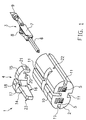
- Fig. 1 is a connector 1 according to the invention with a contact housing 2, a contact connection element 3 and a locking element 4 shown.
- the contact housing 2 is intended for a two-pin connector, passing through each of two parallel holes 5 a pin 6 of a contact connection element 3 can be passed through, too if only one contact connection element 3 is shown in FIG. 1.
- the contact housing has an approximately T-shaped incision 10, in which the locking element 4 can be used with a positive fit. Furthermore, about the cross section of the contact housing 2 circumferentially distributed three longitudinal grooves 11 are provided, with which the Contact housing on complementarily shaped longitudinal ribs 12 of a connector housing 13 is insertable, which is shown in Fig. 2.
- the locking element 4 is approximately T-shaped or anchored, the T-foot an actuating arm 14 and the T-beam an approximately yoke-like design transverse to the foot Engagement section 15 forms.
- the underside of the actuating arm facing the contact housing 2 has two in one obtuse angles to each other sub-surfaces 16, which on a V-edge 17 adjoin each other.
- a shoulder 18 is provided, which in the inserted Condition on a paragraph 19 of the connector housing shown in FIG. 4 13 is present.
- the engagement section 15 has a shape on each side arm on the underside 20, which is approximately the top outline of the contact connection element to be gripped behind 3 corresponds.
- a hole 21 is provided on the side of each arm, which is in an engaged position a through hole 22 provided laterally on the contact housing 2 is aligned.
- the actuating arm 14 has a bevel 23 to the top towards.
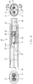
- the contact housing 2 and the locking element 4 are together in the housing 13 of the connector assembly 24 shown inserted.
- the contact housing has an approximately oval cross section with two rear insertion shafts 25 into which One contact connection element 3 can be inserted, which is shown in FIG. 2 for reasons of clarity is omitted.
- the contact housing 2 is inserted into the connector housing 24 through an opening 26 and rests on the end of its end paragraph 27.
- the locking element 4 is in the incision 10 is inserted and protrudes with a portion of the actuating arm 14 the end of the contact connection element 3 facing the opening 26.
- the locking element 4 is in a release position in which the actuating arm 14 arranged slightly obliquely to the longitudinal axis 28 of the connector housing 24 and the engaging portion 15 is deflected upward so that in the illustrated Longitudinal cross section approximately radially behind the opening of the insertion shaft 25.
- a locking projection 29 is provided on the end face, which in the release position shown is without engagement with another component.
- the locking element lies with a stop surface 13 of the engagement section 15 inside on through the wall of the connector housing 13 formed stop portion 31, so that thereby the pivoting movement in the release position is limited.
- FIG. 3 shows an enlarged section of the longitudinal cross section of FIG. 2.
- the contact connection element 3 is shown inserted in the contact housing 2 and gripped by the locking element 4.
- the locking element 4 is pivoted into the engaged position, i.e. in the direction of arrow 32, clockwise in relation to the release position.
- the actuating arm 14 lies with a stop surface 4 on a stop section 13 of the connector housing 13.
- the stop portion 31 is through the inner Wall of the connector housing 13 formed.
- the engagement section 15 engages positively behind the bezel 7, so that the Contact connecting element 3 locked and is not axially displaceable.
- the locking projection 29 engages behind an edge 33 of the contact housing 2, so that the Actuating arm 14 is releasably locked against pivoting back.
- a mating connector 34 with a dashed outline is schematically in the connector housing 13 is shown approximately in face-to-face contact with the contact housing 2.
- the mating connector 34 has a recess 35, approximately complementary to the actuating arm 14, which extends into the recess 35.
- the actuating arm 14 lies on the wall of the recess 35 in such a way that it does not run counter to the arrow direction 32 Release direction can be pivoted counterclockwise.
- the rotary bearing of the locking element 4 is shown.
- the one that serves as a seesaw Locking element is approximately in the middle of a gable-shaped cross section Support projection 36 of the contact housing 2 placed and around this support projection 36 rotatably mounted in the sense of a fulcrum. With an arrow 37 is the direction of rotation shown towards the release position.
- the actuating arm is designed with the V-edge shown in FIG. 1, it lies preferably the V-edge 17 directly on the support projection 36. 4 is as Modification of an actuating arm 14 with a continuously straight underside shown.
- a locking pin (not shown, can be on the side be inserted through the holes 21, 22 so that the locking element 4 does not twist can be.
- the locking element is positively inserted into the incision 10.
- the contact connector 3 is connected to a line 9 and on the back into the connector housing 13 inserted, pulled through and inserted into the contact housing 2 until the locking lug 8 engages behind the paragraph 38.
- the locking element is 4 pivoted around the support projection 36 in the release position, so that the Outline of the border 7 can easily lead through the formation 20.
- the locking element 4 is pivoted into the engagement position so that it surrounds 7 positively engages behind. In the engaged position, the locking element 4 is over the locking projection 29 releasably locked.
- the assembled connector 1 is in the connector housing 13 introduced.
- the operating arm 14 can be operated, so that the Contact securing in this position is also releasable. Then the mating connector also inserted into the opening 26. Due to the approximately positive connection of the actuating arm 14 in the recess 35 is a release of the locking element 4th prevented.
- the operating arm can be operated operate with the help of an elongated object through the opening 26.
- the engagement position forms the bevel 23 relative to the connector housing 13 a pocket-like recess, which as an actuating aid for pivoting in Towards the release position.
- the locking via the locking element 4 serves as a second contact securing while the locking via the locking lug 8 serves as the first contact securing.
Landscapes
- Fuses (AREA)
- Details Of Connecting Devices For Male And Female Coupling (AREA)
- Connector Housings Or Holding Contact Members (AREA)
Abstract
Description
- Fig. 1
- eine perspektivische Darstellung eines erfindungsgemäßen Steckers mit Kontaktgehäuse, Kontaktanschlusselement und Arretierelement,
- Fig. 2
- drei zueinander geklappt dargestellte Ansichten eines erfindungsgemäßen Steckers in Freigabestellung,
- Fig. 3
- einen Längsschnitt durch einen erfindungsgemäßen Stecker in Eingriffsstellung mit eingeführtem Kontaktanschlusselement, längs der Schnittlinie III-III in Fig. 2 und
- Fig. 4
- einen Längsschnitt durch einen erfindungsgemäßen Stecker in Eingriffsstellung längs der Schnittlinie IV-IV in Fig. 2.
Claims (19)
- Stecker (1) für eine Steckverbinderanordnung (24), mit einem Kontaktgehäuse (2), in welchem ein Kontaktanschlusselement (3) über eine Kontaktsicherung (4) befestigbar ist, wobei die Kontaktsicherung (4) ein das Kontaktanschlusselement (3) an dem Kontaktgehäuse (2) befestigendes Arretierelement (4) aufweist, sowie das Arretierelement (4) zwischen einer Freigabestellung und einer das Kontaktanschlusselement (3) an dem Kontaktgehäuse (2) sichernden Eingriffsstellung verdrehbar gelagert und als Wippe ausgebildet ist, dadurch gekennzeichnet, dass ein Schwenklager des Arretierelements (4) als Auflagevorsprung (36) des Kontaktgehäuses (2) ausgebildet ist.
- Stecker nach Anspruch 1, dadurch gekennzeichnet, dass das Arretierelement (4) in Eingriffsstellung einen Absatz des Kontaktanschlusselements (3) formschlüssig hintergreift.
- Stecker nach Anspruch 1 oder 2, dadurch gekennzeichnet, dass der Auflagevorsprung (36) einen giebelartigen Querschnitt aufweist.
- Stecker nach einem der vorhergehenden Ansprüche, dadurch gekennzeichnet, dass das Arretierelement (4) einen Betätigungsarm (14) und einen nahe einem seiner Enden angeordneten Eingriffsabschnitt (15) aufweist.
- Stecker nach Anspruch 4, dadurch gekennzeichnet, dass der Eingriffsabschnitt (15) jochartig quer zu dem Betätigungsarm (14) ausgebildet ist.
- Stecker nach Anspruch 4 oder 5, dadurch gekennzeichnet, dass sich der Betätigungsarm (14) etwa axial in Richtung des zu kontaktierenden Gegensteckers (34) erstreckt.
- Stecker nach einem der Ansprüche 4 bis 6, dadurch gekennzeichnet, dass sich der Betätigungsarm (14) axial über das Kontaktgehäuse (2) hinausragend erstreckt.
- Stecker nach einem der vorhergehenden Ansprüche, dadurch gekennzeichnet, dass ein Eingriffsabschnitt (15) des Arretierelements (4) wenigstens bereichsweise eine etwa dem Umriss des Kontaktanschlusselements (3) derart angepasste Ausformungen (20) aufweist, dass das Kontaktanschlusselement (3) in Freigabestellung beim Einführen oder Lösen durch die Ausformung (20) bewegbar ist.
- Stecker nach einem der vorhergehenden Ansprüche, dadurch gekennzeichnet, dass das Arretierelement (4) lösbar an dem Kontaktgehäuse (2) angebracht ist.
- Stecker nach einem der vorhergehenden Ansprüche, dadurch gekennzeichnet, dass das Arretierelement (4) formschlüssig in eine Ausnehmung (10) des Kontaktgehäuses (2) einsetzbar ist.
- Stecker nach einem der vorhergehenden Ansprüche, dadurch gekennzeichnet, dass das Arretierelement (4) in Eingriffsstellung verriegelt ist.
- Stecker nach einem der vorhergehenden Ansprüche, dadurch gekennzeichnet, dass das Arretierelement (4) in Eingriffsstellung lösbar an dem Kontaktgehäuse (2) verrastet ist.
- Steckverbinderanordnung (24) mit einem Stecker (1) nach einem der vorhergehenden Ansprüche, wobei der Stecker (1) in einem Steckverbindergehäuse (13) aufgenommen ist.
- Steckverbinderanordnung nach Anspruch 13, dadurch gekennzeichnet, dass das Arretierelement (4) in Eingriffsstellung mit einem Anschlag (30) an einem inneren, die Schwenkbewegung begrenzenden Anschlagabschnitt (31) des Steckverbindergehäuses (13) anliegt.
- Steckverbinderanordnung nach Anspruch 13 oder 14, dadurch gekennzeichnet, dass sich ein Abschnitt des Arretierelements (4) in Eingriffsstellung in eine die Schwenkbewegung des Arretierelements (4) unterbindende Ausnehmung (35) des angeschlossenen Gegensteckers (34) erstreckt.
- Steckverbinderanordnung nach einem der Ansprüche 13 bis 15, dadurch gekennzeichnet, dass das Arretierelement (4) mit einem Absatz (18) in axialer Einführrichtung (28) in das Gehäuse (13) an einem Gegenabsatz (19) des Steckverbindergehäuses (13) anliegt.
- Steckverbinderanordnung nach einem der Ansprüche 13 bis 16, dadurch gekennzeichnet, dass der Stecker (1) durch eine Öffnung (26) in das Steckverbindergehäuse (13) eingeführt ist und das Arretierelement (4) durch diese Öffnung (26) betätigbar ist.
- Wasserdichte Steckverbinderanordnung nach einem der Ansprüche 13 bis 17.
- Steckverbinderanordnung (24) mit einem Stecker (1), der in einem Steckverbindergehäuse (13) aufgenommen ist, wobei der Stecker (1) ein Kontaktgehäuse (2), in welchem ein Kontaktanschlusselement (3) über eine Kontaktsicherung (4) befestigbar ist, aufweist, wobei die Kontaktsicherung (4) ein das Kontaktanschlusselement (3) an dem Kontaktgehäuse (2) befestigendes Arretierelement (4) aufweist, wobei das Arretierelement (4) zwischen einer Freigabestellung und einer das Kontaktanschlusselement (3) an dem Kontaktgehäuse (2) sichernder Eingriffsstellung verdrehbar gelagert ist, wobei das Arretierelement als Wippe ausgebildet ist, dadurch gekennzeichnet, dass das Arretierelement (4) einen Betätigungsarm (14) und einen nahe einem seiner Enden angeordneten Eingriffsabschnitt (15) aufweist, dass sich der Betätigungsarm (14) axial über das Kontaktgehäuse (2) hinausragend erstreckt und dass der Stecker (1) durch eine Öffnung (26) in das Verbindergehäuse (13) eingefügt ist und dass das Verschwenken des Arretierelementes (4) mittels des Betätigungsarmes (14) durch diese Öffnung (26) erfolgt.
Applications Claiming Priority (2)
| Application Number | Priority Date | Filing Date | Title |
|---|---|---|---|
| DE10045708 | 2000-09-15 | ||
| DE10045708 | 2000-09-15 |
Publications (3)
| Publication Number | Publication Date |
|---|---|
| EP1189311A2 true EP1189311A2 (de) | 2002-03-20 |
| EP1189311A3 EP1189311A3 (de) | 2002-10-23 |
| EP1189311B1 EP1189311B1 (de) | 2005-06-22 |
Family
ID=7656341
Family Applications (1)
| Application Number | Title | Priority Date | Filing Date |
|---|---|---|---|
| EP01120101A Expired - Lifetime EP1189311B1 (de) | 2000-09-15 | 2001-08-21 | Stecker für eine Steckverbinderanordnung |
Country Status (2)
| Country | Link |
|---|---|
| EP (1) | EP1189311B1 (de) |
| DE (1) | DE50106572D1 (de) |
Cited By (2)
| Publication number | Priority date | Publication date | Assignee | Title |
|---|---|---|---|---|
| EP3288121A1 (de) * | 2016-08-26 | 2018-02-28 | Hirschmann Automotive GmbH | Komplett abgedichteter steckverbinder mit verbesserten haltekräften |
| EP4468525A1 (de) * | 2023-05-23 | 2024-11-27 | Aptiv Technologies AG | Abgedichteter verbinder mit selbstverriegelndem tpa |
Family Cites Families (4)
| Publication number | Priority date | Publication date | Assignee | Title |
|---|---|---|---|---|
| JP2813717B2 (ja) * | 1993-04-28 | 1998-10-22 | 矢崎総業株式会社 | シールドコネクタ |
| JP3106286B2 (ja) * | 1995-06-30 | 2000-11-06 | 矢崎総業株式会社 | リヤホルダー付きコネクタ |
| JP3188380B2 (ja) * | 1995-06-30 | 2001-07-16 | 矢崎総業株式会社 | リヤホルダー付きコネクタ |
| DE19613050C1 (de) * | 1996-04-01 | 1997-10-23 | Kostal Leopold Gmbh & Co Kg | Elektrisches Steckverbindungsteil |
-
2001
- 2001-08-21 DE DE50106572T patent/DE50106572D1/de not_active Expired - Lifetime
- 2001-08-21 EP EP01120101A patent/EP1189311B1/de not_active Expired - Lifetime
Cited By (2)
| Publication number | Priority date | Publication date | Assignee | Title |
|---|---|---|---|---|
| EP3288121A1 (de) * | 2016-08-26 | 2018-02-28 | Hirschmann Automotive GmbH | Komplett abgedichteter steckverbinder mit verbesserten haltekräften |
| EP4468525A1 (de) * | 2023-05-23 | 2024-11-27 | Aptiv Technologies AG | Abgedichteter verbinder mit selbstverriegelndem tpa |
Also Published As
| Publication number | Publication date |
|---|---|
| DE50106572D1 (de) | 2005-07-28 |
| EP1189311B1 (de) | 2005-06-22 |
| EP1189311A3 (de) | 2002-10-23 |
Similar Documents
| Publication | Publication Date | Title |
|---|---|---|
| EP0632699B1 (de) | Druckknopf zur arretierung von schnürsenkeln | |
| EP0327175B1 (de) | Drehknopf für Steuergeräte o. dgl. | |
| EP1290303B1 (de) | Stangenschloss für ein verschlusssystem | |
| EP1766165B1 (de) | Vorrichtung zur betätigung eines in einer tür, einer klappe od. dgl. eingebauten schlosses, insbesondere bei einem fahrzeug | |
| DE102004031110A1 (de) | Sicherungsschalter | |
| DE69415333T2 (de) | Gegossene sicherheitsnadel | |
| EP1257018A1 (de) | Elektrischer Steckadapter | |
| AT11207U1 (de) | Kupplungsvorrichtung mit panikfunktion für elektromechanische feststellvorrichtungen | |
| WO2017036439A1 (de) | Halterahmen für steckverbindermodule | |
| DE69801689T2 (de) | Verriegelungsvorrichtung für eine scharnierende Schachtabdeckung | |
| DE69932168T2 (de) | Schlüssel mit beweglichem element, schlüsselkopf und schloss | |
| WO2018036684A1 (de) | Kraftfahrzeug-griffanordnung | |
| DE2901213C2 (de) | Lösbare Stiftverbindung für Bauelemente | |
| EP2949842B1 (de) | Türgriffanordnung für ein kraftfahrzeug | |
| EP4012200B1 (de) | Federbelasteter rastbolzen | |
| WO1991018173A1 (de) | Möbelscharnier | |
| DE10106228A1 (de) | Sicherheitsschalter mit Entriegelungsscheibe | |
| DE60200336T2 (de) | Kastenverschlussvorrichtung | |
| DE10217488A1 (de) | Vorrichtung zum Betätigen eines Verschlusses von Türen, Klappen od.dgl., insbesondere an Fahrzeugen | |
| DE102020106634B3 (de) | Elektrische Steckverbindung und Entriegelungselement | |
| EP1987217A1 (de) | Einrichtung zum festlegen eines tür- oder fenstergriffes | |
| DE19828414A1 (de) | Elektrische Verbinderanordnung mit Verriegelungsmechanismus | |
| EP1189311B1 (de) | Stecker für eine Steckverbinderanordnung | |
| EP1659250B1 (de) | Fenster, Tür oder dergleichen mit einer Eckumlenkung | |
| DE19526660B4 (de) | Elektromechanisches Schloß |
Legal Events
| Date | Code | Title | Description |
|---|---|---|---|
| PUAI | Public reference made under article 153(3) epc to a published international application that has entered the european phase |
Free format text: ORIGINAL CODE: 0009012 |
|
| AK | Designated contracting states |
Kind code of ref document: A2 Designated state(s): AT BE CH CY DE DK ES FI FR GB GR IE IT LI LU MC NL PT SE TR |
|
| AX | Request for extension of the european patent |
Free format text: AL;LT;LV;MK;RO;SI |
|
| PUAL | Search report despatched |
Free format text: ORIGINAL CODE: 0009013 |
|
| AK | Designated contracting states |
Kind code of ref document: A3 Designated state(s): AT BE CH CY DE DK ES FI FR GB GR IE IT LI LU MC NL PT SE TR |
|
| AX | Request for extension of the european patent |
Free format text: AL;LT;LV;MK;RO;SI |
|
| 17P | Request for examination filed |
Effective date: 20021007 |
|
| 17Q | First examination report despatched |
Effective date: 20030218 |
|
| AKX | Designation fees paid |
Designated state(s): DE FR GB IT |
|
| GRAP | Despatch of communication of intention to grant a patent |
Free format text: ORIGINAL CODE: EPIDOSNIGR1 |
|
| GRAS | Grant fee paid |
Free format text: ORIGINAL CODE: EPIDOSNIGR3 |
|
| GRAA | (expected) grant |
Free format text: ORIGINAL CODE: 0009210 |
|
| AK | Designated contracting states |
Kind code of ref document: B1 Designated state(s): DE FR GB IT |
|
| REG | Reference to a national code |
Ref country code: GB Ref legal event code: FG4D Free format text: NOT ENGLISH |
|
| REF | Corresponds to: |
Ref document number: 50106572 Country of ref document: DE Date of ref document: 20050728 Kind code of ref document: P |
|
| GBT | Gb: translation of ep patent filed (gb section 77(6)(a)/1977) |
Effective date: 20050927 |
|
| ET | Fr: translation filed | ||
| PLBE | No opposition filed within time limit |
Free format text: ORIGINAL CODE: 0009261 |
|
| STAA | Information on the status of an ep patent application or granted ep patent |
Free format text: STATUS: NO OPPOSITION FILED WITHIN TIME LIMIT |
|
| 26N | No opposition filed |
Effective date: 20060323 |
|
| REG | Reference to a national code |
Ref country code: DE Ref legal event code: R081 Ref document number: 50106572 Country of ref document: DE Owner name: TE CONNECTIVITY GERMANY GMBH, DE Free format text: FORMER OWNER: TYCO ELECTRONICS AMP GMBH, 64625 BENSHEIM, DE |
|
| REG | Reference to a national code |
Ref country code: FR Ref legal event code: PLFP Year of fee payment: 15 |
|
| REG | Reference to a national code |
Ref country code: FR Ref legal event code: CD Owner name: TE CONNECTIVITY GERMANY GMBH Effective date: 20151027 |
|
| REG | Reference to a national code |
Ref country code: FR Ref legal event code: PLFP Year of fee payment: 16 |
|
| REG | Reference to a national code |
Ref country code: FR Ref legal event code: PLFP Year of fee payment: 17 |
|
| REG | Reference to a national code |
Ref country code: FR Ref legal event code: PLFP Year of fee payment: 18 |
|
| PGFP | Annual fee paid to national office [announced via postgrant information from national office to epo] |
Ref country code: IT Payment date: 20180823 Year of fee payment: 18 Ref country code: FR Payment date: 20180712 Year of fee payment: 18 Ref country code: DE Payment date: 20180807 Year of fee payment: 18 |
|
| PGFP | Annual fee paid to national office [announced via postgrant information from national office to epo] |
Ref country code: GB Payment date: 20180815 Year of fee payment: 18 |
|
| REG | Reference to a national code |
Ref country code: DE Ref legal event code: R119 Ref document number: 50106572 Country of ref document: DE |
|
| GBPC | Gb: european patent ceased through non-payment of renewal fee |
Effective date: 20190821 |
|
| PG25 | Lapsed in a contracting state [announced via postgrant information from national office to epo] |
Ref country code: FR Free format text: LAPSE BECAUSE OF NON-PAYMENT OF DUE FEES Effective date: 20190831 Ref country code: DE Free format text: LAPSE BECAUSE OF NON-PAYMENT OF DUE FEES Effective date: 20200303 |
|
| PG25 | Lapsed in a contracting state [announced via postgrant information from national office to epo] |
Ref country code: IT Free format text: LAPSE BECAUSE OF NON-PAYMENT OF DUE FEES Effective date: 20190821 Ref country code: GB Free format text: LAPSE BECAUSE OF NON-PAYMENT OF DUE FEES Effective date: 20190821 |